2002 NISSAN TERRANO display
[x] Cancel search: displayPage 16 of 1767
Self-diagnosis
After performing this procedure, place check marks for results on
the ªDIAGNOSTIC WORKSHEETº, AT-24. Reference pages are
provided following the items.
SELF-DIAGNOSTIC PROCEDURE (With CONSULT-II)
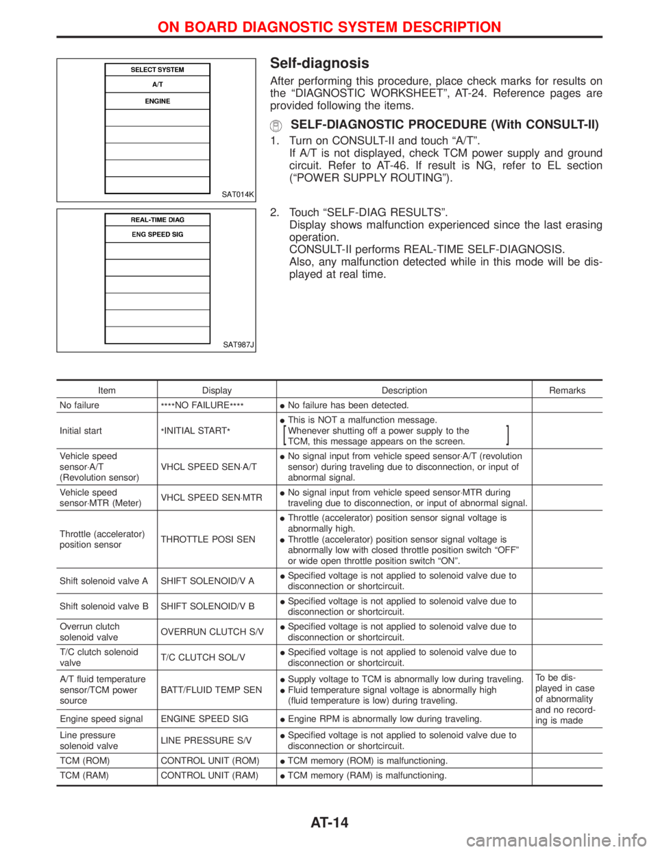
1. Turn on CONSULT-II and touch ªA/Tº.
If A/T is not displayed, check TCM power supply and ground
circuit. Refer to AT-46. If result is NG, refer to EL section
(ªPOWER SUPPLY ROUTINGº).
2. Touch ªSELF-DIAG RESULTSº.
Display shows malfunction experienced since the last erasing
operation.
CONSULT-II performs REAL-TIME SELF-DIAGNOSIS.
Also, any malfunction detected while in this mode will be dis-
played at real time.
Item Display Description Remarks
No failure
****NO FAILURE
****INo failure has been detected.
Initial start
*INITIAL START
*IThis is NOT a malfunction message.
Whenever shutting off a power supply to the
TCM, this message appears on the screen.
[]
Vehicle speed
sensor×A/T
(Revolution sensor)VHCL SPEED SEN×A/TINo signal input from vehicle speed sensor×A/T (revolution
sensor) during traveling due to disconnection, or input of
abnormal signal.
Vehicle speed
sensor×MTR (Meter)VHCL SPEED SEN×MTRINo signal input from vehicle speed sensor×MTR during
traveling due to disconnection, or input of abnormal signal.
Throttle (accelerator)
position sensorTHROTTLE POSI SENIThrottle (accelerator) position sensor signal voltage is
abnormally high.
IThrottle (accelerator) position sensor signal voltage is
abnormally low with closed throttle position switch ªOFFº
or wide open throttle position switch ªONº.
Shift solenoid valve A SHIFT SOLENOID/V AISpecified voltage is not applied to solenoid valve due to
disconnection or shortcircuit.
Shift solenoid valve B SHIFT SOLENOID/V BISpecified voltage is not applied to solenoid valve due to
disconnection or shortcircuit.
Overrun clutch
solenoid valveOVERRUN CLUTCH S/VISpecified voltage is not applied to solenoid valve due to
disconnection or shortcircuit.
T/C clutch solenoid
valveT/C CLUTCH SOL/VISpecified voltage is not applied to solenoid valve due to
disconnection or shortcircuit.
A/T fluid temperature
sensor/TCM power
sourceBATT/FLUID TEMP SENISupply voltage to TCM is abnormally low during traveling.
IFluid temperature signal voltage is abnormally high
(fluid temperature is low) during traveling.To be dis-
played in case
of abnormality
and no record-
ing is made Engine speed signal ENGINE SPEED SIGIEngine RPM is abnormally low during traveling.
Line pressure
solenoid valveLINE PRESSURE S/VISpecified voltage is not applied to solenoid valve due to
disconnection or shortcircuit.
TCM (ROM) CONTROL UNIT (ROM)ITCM memory (ROM) is malfunctioning.
TCM (RAM) CONTROL UNIT (RAM)ITCM memory (RAM) is malfunctioning.
SAT014K
SAT987J
ON BOARD DIAGNOSTIC SYSTEM DESCRIPTION
AT-14
Page 22 of 1767
Diagnosis by CONSULT-II
NOTICE
1. The CONSULT-II electrically displays shift timing and lock-up timing (that is, operation timing of each
solenoid).
Check for time difference between actual shift timing and the CONSULT-II display. If the difference is
noticeable, mechanical parts (except solenoids, sensors, etc.) may be malfunctioning. Check mechanical
parts using applicable diagnostic procedures.
2. Shift schedule (which implies gear position) displayed on CONSULT-II and that indicated in Service Manual
may differ slightly. This occurs because of the following reasons:
IActual shift schedule has more or less tolerance or allowance,
IShift schedule indicated in Service Manual refers to the point where shifts start. Gear position displayed
on CONSULT-II indicates the point where shifts are completed.
3. Shift solenoid valve ªAº or ªBº is displayed on CONSULT-II at the start of shifting. Gear position is displayed
upon completion of shifting (which is computed by TCM).
4. Additional CONSULT-II information can be found in the Operation Manual supplied with the CONSULT-II
unit.
SELF-DIAGNOSTIC RESULT TEST MODE
Refer to AT-14.
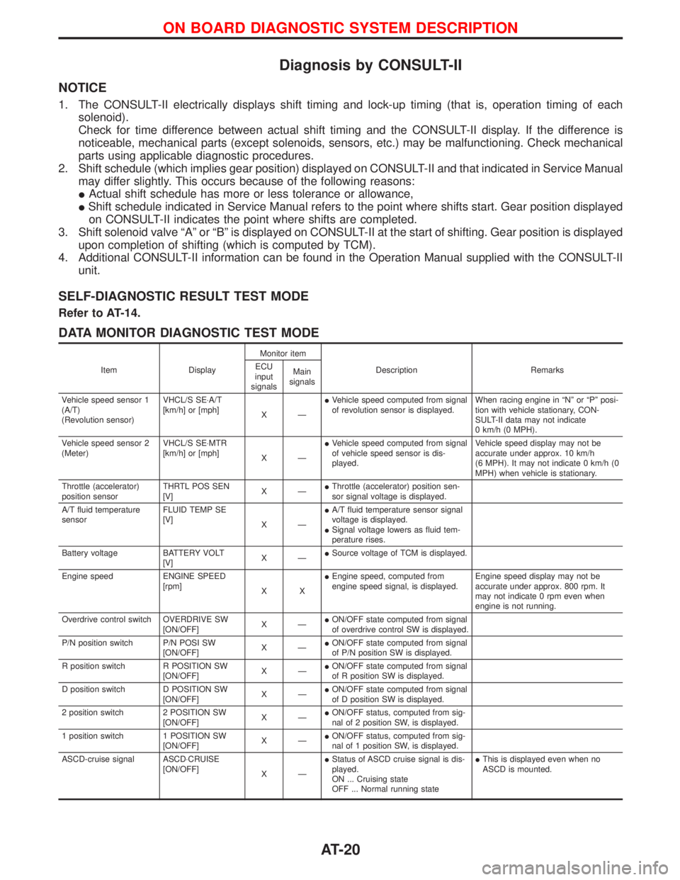
DATA MONITOR DIAGNOSTIC TEST MODE
Item DisplayMonitor item
Description Remarks ECU
input
signalsMain
signals
Vehicle speed sensor 1
(A/T)
(Revolution sensor)VHCL/S SE×A/T
[km/h] or [mph]
XÐIVehicle speed computed from signal
of revolution sensor is displayed.When racing engine in ªNº or ªPº posi-
tion with vehicle stationary, CON-
SULT-II data may not indicate
0 km/h (0 MPH).
Vehicle speed sensor 2
(Meter)VHCL/S SE×MTR
[km/h] or [mph]
XÐIVehicle speed computed from signal
of vehicle speed sensor is dis-
played.Vehicle speed display may not be
accurate under approx. 10 km/h
(6 MPH). It may not indicate 0 km/h (0
MPH) when vehicle is stationary.
Throttle (accelerator)
position sensorTHRTL POS SEN
[V]XÐIThrottle (accelerator) position sen-
sor signal voltage is displayed.
A/T fluid temperature
sensorFLUID TEMP SE
[V]
XÐIA/T fluid temperature sensor signal
voltage is displayed.
ISignal voltage lowers as fluid tem-
perature rises.
Battery voltage BATTERY VOLT
[V]XÐISource voltage of TCM is displayed.
Engine speed ENGINE SPEED
[rpm]
XXIEngine speed, computed from
engine speed signal, is displayed.Engine speed display may not be
accurate under approx. 800 rpm. It
may not indicate 0 rpm even when
engine is not running.
Overdrive control switch OVERDRIVE SW
[ON/OFF]XÐION/OFF state computed from signal
of overdrive control SW is displayed.
P/N position switch P/N POSI SW
[ON/OFF]XÐION/OFF state computed from signal
of P/N position SW is displayed.
R position switch R POSITION SW
[ON/OFF]XÐION/OFF state computed from signal
of R position SW is displayed.
D position switch D POSITION SW
[ON/OFF]XÐION/OFF state computed from signal
of D position SW is displayed.
2 position switch 2 POSITION SW
[ON/OFF]XÐION/OFF status, computed from sig-
nal of 2 position SW, is displayed.
1 position switch 1 POSITION SW
[ON/OFF]XÐION/OFF status, computed from sig-
nal of 1 position SW, is displayed.
ASCD-cruise signal ASCD×CRUISE
[ON/OFF]
XÐIStatus of ASCD cruise signal is dis-
played.
ON ... Cruising state
OFF ... Normal running stateIThis is displayed even when no
ASCD is mounted.
ON BOARD DIAGNOSTIC SYSTEM DESCRIPTION
AT-20
Page 23 of 1767
![NISSAN TERRANO 2002 Service Repair Manual Item DisplayMonitor item
Description Remarks ECU
input
signalsMain
signals
ASCD-OD cut signal ASCD×OD CUT
[ON/OFF]
XÐIStatus of ASCD×OD release signal is
displayed.
ON ... OD released
OFF ... OD no NISSAN TERRANO 2002 Service Repair Manual Item DisplayMonitor item
Description Remarks ECU
input
signalsMain
signals
ASCD-OD cut signal ASCD×OD CUT
[ON/OFF]
XÐIStatus of ASCD×OD release signal is
displayed.
ON ... OD released
OFF ... OD no](/manual-img/5/57393/w960_57393-22.png)
Item DisplayMonitor item
Description Remarks ECU
input
signalsMain
signals
ASCD-OD cut signal ASCD×OD CUT
[ON/OFF]
XÐIStatus of ASCD×OD release signal is
displayed.
ON ... OD released
OFF ... OD not releasedIThis is displayed even when no
ASCD is mounted.
Kickdown switch KICKDOWN SW
[ON/OFF]XÐION/OFF status, computed from sig-
nal of kickdown SW, is displayed.IThis is displayed even when no
kickdown switch is equipped.
A/T mode switch POWER SHIFT SW
[ON/OFF]XÐION/OFF state computed from signal
of SPORT shift SW is displayed.
Closed throttle position
switchCLOSED THL/SW
[ON/OFF] X ÐION/OFF status, computed from sig-
nal of closed throttle (accelerator)
position SW, is displayed.
Wide open throttle posi-
tion switchW/O THRL/P-SW
[ON/OFF] X ÐION/OFF status, computed from sig-
nal of wide open throttle (accelera-
tor) position SW, is displayed.
A/T mode switch HOLD SW
[ON/OFF]XÐION/OFF status, computed from sig-
nal of SNOW shift SW, is displayed.
Gear position GEAR
ÐXIGear position data used for compu-
tation by TCM, is displayed.
Selector lever position SLCT LVR POSI
ÐXISelector lever position data, used
for computation by TCM, is dis-
played.IA specific value used for control is
displayed if fail-safe is activated due
to error.
Vehicle speed VEHICLE SPEED
[km/h] or [mph]ÐXIVehicle speed data, used for com-
putation by TCM, is displayed.
Throttle (accelerator)
positionTHROTTLE POSI
[/8] Ð XIThrottle (accelerator) position data,
used for computation by TCM, is
displayed.IA specific value used for control is
displayed if fail-safe is activated due
to error.
Line pressure duty LINE PRES DTY
[%] Ð XIControl value of line pressure sole-
noid valve, computed by TCM from
each input signal, is displayed.
Torque converter clutch
solenoid valve dutyTCC S/V DUTY
[%]
ÐXIControl value of torque converter
clutch solenoid valve, computed by
TCM from each input signal, is dis-
played.
Shift solenoid valve A SHIFT S/V A
[ON/OFF] Ð XIControl value of shift solenoid valve
A, computed by TCM from each
input signal, is displayed.Control value of solenoid is displayed
even if solenoid circuit is discon-
nected.
The ªOFFº signal is displayed if sole-
noid circuit is shorted. Shift solenoid valve B SHIFT S/V B
[ON/OFF] Ð XIControl value of shift solenoid valve
B, computed by TCM from each
input signal, is displayed.
Overrun clutch solenoid
valveOVERRUN/C S/V
[ON/OFF] Ð XIControl value of overrun clutch sole-
noid valve computed by TCM from
each input signal is displayed.
Self-diagnosis display
lamp
(SPORT indicator lamp)SELF-D DP LMP
[ON/OFF] Ð XIControl status of SPORT indicator
lamp is displayed.
X: Applicable
Ð: Not applicable
ON BOARD DIAGNOSTIC SYSTEM DESCRIPTION
Diagnosis by CONSULT-II (Cont'd)
AT-21
Page 39 of 1767
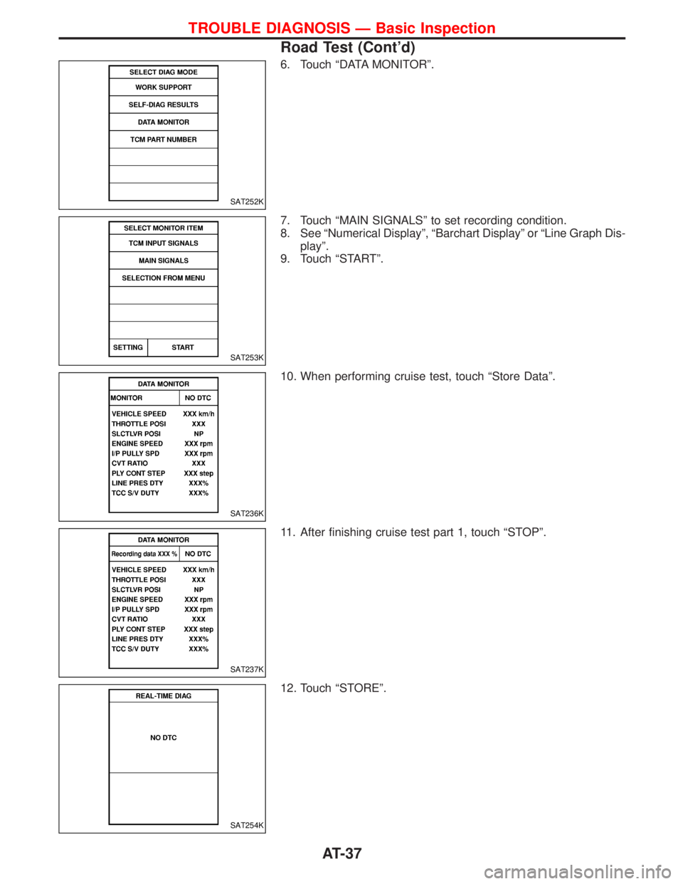
6. Touch ªDATA MONITORº.
7. Touch ªMAIN SIGNALSº to set recording condition.
8. See ªNumerical Displayº, ªBarchart Displayº or ªLine Graph Dis-
playº.
9. Touch ªSTARTº.
10. When performing cruise test, touch ªStore Dataº.
11. After finishing cruise test part 1, touch ªSTOPº.
12. Touch ªSTOREº.
SAT252K
SAT253K
SAT236K
SAT237K
SAT254K
TROUBLE DIAGNOSIS Ð Basic Inspection
Road Test (Cont'd)
AT-37
Page 40 of 1767
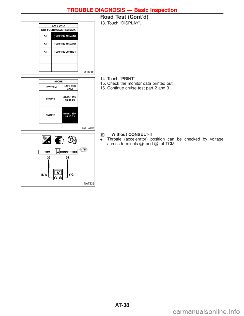
13. Touch ªDISPLAYº.
14. Touch ªPRINTº.
15. Check the monitor data printed out.
16. Continue cruise test part 2 and 3.
Without CONSULT-II
IThrottle (accelerator) position can be checked by voltage
across terminalsq
34andq35of TCM.
SAT608J
SAT238K
NAT235
TROUBLE DIAGNOSIS Ð Basic Inspection
Road Test (Cont'd)
AT-38
Page 92 of 1767
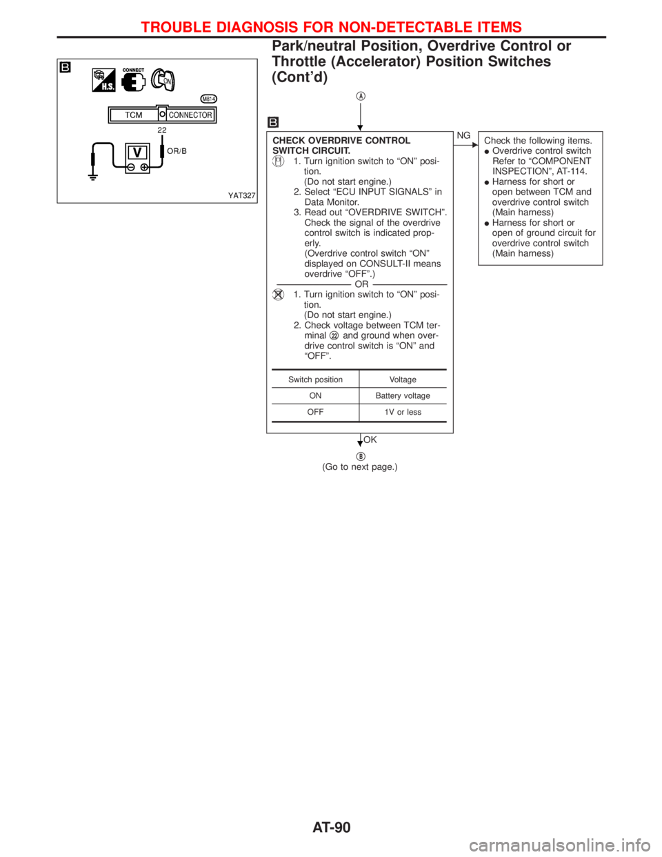
qA
CHECK OVERDRIVE CONTROL
SWITCH CIRCUIT.
1. Turn ignition switch to ªONº posi-
tion.
(Do not start engine.)
2. Select ªECU INPUT SIGNALSº in
Data Monitor.
3. Read out ªOVERDRIVE SWITCHº.
Check the signal of the overdrive
control switch is indicated prop-
erly.
(Overdrive control switch ªONº
displayed on CONSULT-II means
overdrive ªOFFº.)
-----------------------------------------------------------------------------------------------------------------------OR -----------------------------------------------------------------------------------------------------------------------
1. Turn ignition switch to ªONº posi-
tion.
(Do not start engine.)
2. Check voltage between TCM ter-
minalq
22and ground when over-
drive control switch is ªONº and
ªOFFº.
OK
ENG
Check the following items.
IOverdrive control switch
Refer to ªCOMPONENT
INSPECTIONº, AT-114.
IHarness for short or
open between TCM and
overdrive control switch
(Main harness)
IHarness for short or
open of ground circuit for
overdrive control switch
(Main harness)
qB(Go to next page.)
Switch position Voltage
ON Battery voltage
OFF 1V or less
YAT327
H
H
TROUBLE DIAGNOSIS FOR NON-DETECTABLE ITEMS
Park/neutral Position, Overdrive Control or
Throttle (Accelerator) Position Switches
(Cont'd)
AT-90
Page 260 of 1767
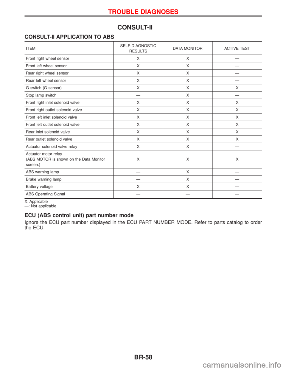
CONSULT-II
CONSULT-II APPLICATION TO ABS
ITEMSELF-DIAGNOSTIC
RESULTSDATA MONITOR ACTIVE TEST
Front right wheel sensor X X Ð
Front left wheel sensor X X Ð
Rear right wheel sensor X X Ð
Rear left wheel sensor X X Ð
G switch (G sensor) X X X
Stop lamp switch Ð X Ð
Front right inlet solenoid valve X X X
Front right outlet solenoid valve X X X
Front left inlet solenoid valve X X X
Front left outlet solenoid valve X X X
Rear inlet solenoid valve X X X
Rear outlet solenoid valve X X X
Actuator solenoid valve relay X X Ð
Actuator motor relay
(ABS MOTOR is shown on the Data Monitor
screen.)XXX
ABS warning lamp Ð X Ð
Brake warning lamp Ð X Ð
Battery voltage X X Ð
ABS Operating Signal Ð Ð Ð
X: Applicable
Ð: Not applicable
ECU (ABS control unit) part number mode
Ignore the ECU part number displayed in the ECU PART NUMBER MODE. Refer to parts catalog to order
the ECU.
TROUBLE DIAGNOSES
BR-58
Page 372 of 1767
due to receiving external noise, degraded operation of ICs,
etc.
IKeep ECM parts and harnesses dry.
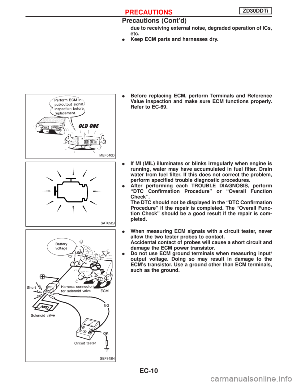
IBefore replacing ECM, perform Terminals and Reference
Value inspection and make sure ECM functions properly.
Refer to EC-69.
IIf MI (MIL) illuminates or blinks irregularly when engine is
running, water may have accumulated in fuel filter. Drain
water from fuel filter. If this does not correct the problem,
perform specified trouble diagnostic procedures.
IAfter performing each TROUBLE DIAGNOSIS, perform
ªDTC Confirmation Procedureº or ªOverall Function
Checkº.
The DTC should not be displayed in the ªDTC Confirmation
Procedureº if the repair is completed. The ªOverall Func-
tion Checkº should be a good result if the repair is com-
pleted.
IWhen measuring ECM signals with a circuit tester, never
allow the two tester probes to contact.
Accidental contact of probes will cause a short circuit and
damage the ECM power transistor.
IDo not use ECM ground terminals when measuring input/
output voltage. Doing so may result in damage to the
ECM's transistor. Use a ground other than ECM terminals,
such as the ground.
MEF040D
SAT652J
SEF348N
PRECAUTIONSZD30DDTi
Precautions (Cont'd)
EC-10