2002 NISSAN TERRANO display
[x] Cancel search: displayPage 686 of 1767
DIAGNOSTIC TEST MODE IÐBULB CHECK
In this mode, the MALFUNCTION INDICATOR on the instrument panel should stay ON. If it remains OFF,
check the bulb. Refer to EL section (ªWARNING LAMPS/WIRING DIAGRAMº) or see EC-452.
DIAGNOSTIC TEST MODE IÐMALFUNCTION WARNING
MI Condition
ON When a malfunction is detected or the ECM's CPU is malfunctioning.
OFF No malfunction.
IThese Diagnostic Trouble Code Numbers are clarified in Diagnostic Test Mode II (SELF-DIAGNOSTIC
RESULTS).
DIAGNOSTIC TEST MODE IIÐSELF-DIAGNOSTIC RESULTS
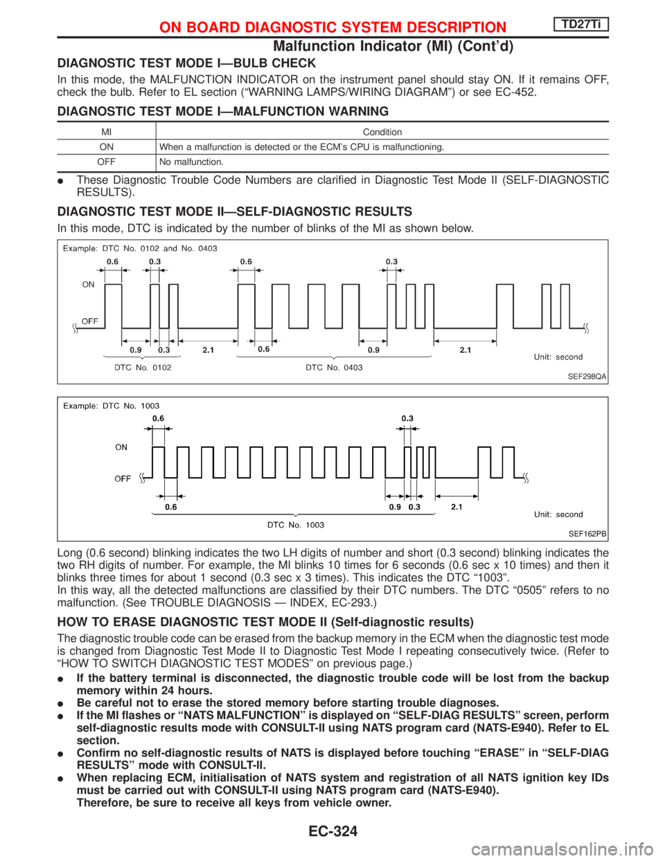
In this mode, DTC is indicated by the number of blinks of the MI as shown below.
Long (0.6 second) blinking indicates the two LH digits of number and short (0.3 second) blinking indicates the
two RH digits of number. For example, the MI blinks 10 times for 6 seconds (0.6 sec x 10 times) and then it
blinks three times for about 1 second (0.3 sec x 3 times). This indicates the DTC ª1003º.
In this way, all the detected malfunctions are classified by their DTC numbers. The DTC ª0505º refers to no
malfunction. (See TROUBLE DIAGNOSIS Ð INDEX, EC-293.)
HOW TO ERASE DIAGNOSTIC TEST MODE II (Self-diagnostic results)
The diagnostic trouble code can be erased from the backup memory in the ECM when the diagnostic test mode
is changed from Diagnostic Test Mode II to Diagnostic Test Mode I repeating consecutively twice. (Refer to
ªHOW TO SWITCH DIAGNOSTIC TEST MODESº on previous page.)
IIf the battery terminal is disconnected, the diagnostic trouble code will be lost from the backup
memory within 24 hours.
IBe careful not to erase the stored memory before starting trouble diagnoses.
IIf the MI flashes or ªNATS MALFUNCTIONº is displayed on ªSELF-DIAG RESULTSº screen, perform
self-diagnostic results mode with CONSULT-II using NATS program card (NATS-E940). Refer to EL
section.
IConfirm no self-diagnostic results of NATS is displayed before touching ªERASEº in ªSELF-DIAG
RESULTSº mode with CONSULT-II.
IWhen replacing ECM, initialisation of NATS system and registration of all NATS ignition key IDs
must be carried out with CONSULT-II using NATS program card (NATS-E940).
Therefore, be sure to receive all keys from vehicle owner.
SEF298QA
SEF162PB
ON BOARD DIAGNOSTIC SYSTEM DESCRIPTIONTD27Ti
Malfunction Indicator (MI) (Cont'd)
EC-324
Page 688 of 1767
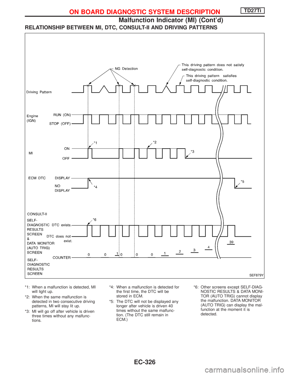
RELATIONSHIP BETWEEN MI, DTC, CONSULT-II AND DRIVING PATTERNS
*1: When a malfunction is detected, MI
will light up.
*2: When the same malfunction is
detected in two consecutive driving
patterns, MI will stay lit up.
*3: MI will go off after vehicle is driven
three times without any malfunc-
tions.*4: When a malfunction is detected for
the first time, the DTC will be
stored in ECM.
*5: The DTC will not be displayed any
longer after vehicle is driven 40
times without the same malfunc-
tion. (The DTC still remain in
ECM.)*6: Other screens except SELF-DIAG-
NOSTIC RESULTS & DATA MONI-
TOR (AUTO TRIG) cannot display
the malfunction. DATA MONITOR
(AUTO TRIG) can display the mal-
function at the moment it is
detected.
SEF879Y
ON BOARD DIAGNOSTIC SYSTEM DESCRIPTIONTD27Ti
Malfunction Indicator (MI) (Cont'd)
EC-326
Page 690 of 1767
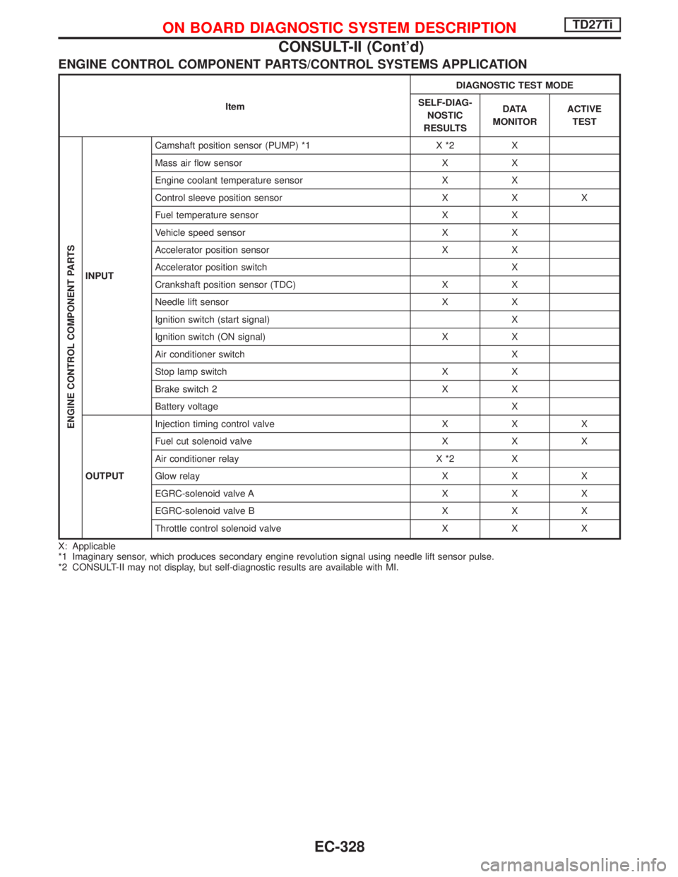
ENGINE CONTROL COMPONENT PARTS/CONTROL SYSTEMS APPLICATION
ItemDIAGNOSTIC TEST MODE
SELF-DIAG-
NOSTIC
RESULTSD ATA
MONITORACTIVE
TEST
ENGINE CONTROL COMPONENT PARTS
INPUTCamshaft position sensor (PUMP) *1 X *2 X
Mass air flow sensor X X
Engine coolant temperature sensor X X
Control sleeve position sensor X X X
Fuel temperature sensor X X
Vehicle speed sensor X X
Accelerator position sensor X X
Accelerator position switch X
Crankshaft position sensor (TDC) X X
Needle lift sensor X X
Ignition switch (start signal) X
Ignition switch (ON signal) X X
Air conditioner switch X
Stop lamp switch X X
Brake switch 2 X X
Battery voltage X
OUTPUTInjection timing control valve X X X
Fuel cut solenoid valve X X X
Air conditioner relay X *2 X
Glow relay X X X
EGRC-solenoid valve A X X X
EGRC-solenoid valve B X X X
Throttle control solenoid valve X X X
X: Applicable
*1 Imaginary sensor, which produces secondary engine revolution signal using needle lift sensor pulse.
*2 CONSULT-II may not display, but self-diagnostic results are available with MI.
ON BOARD DIAGNOSTIC SYSTEM DESCRIPTIONTD27Ti
CONSULT-II (Cont'd)
EC-328
Page 691 of 1767
![NISSAN TERRANO 2002 Service Repair Manual SELF-DIAGNOSTIC MODE
Regarding items detected in ªSELF-DIAG RESULTSº mode, refer to ªTROUBLE DIAGNOSIS Ð INDEXº,
EC-293.
DATA MONITOR MODE
Monitored item
[Unit]ECM
input
signalsMain
signalsDescri NISSAN TERRANO 2002 Service Repair Manual SELF-DIAGNOSTIC MODE
Regarding items detected in ªSELF-DIAG RESULTSº mode, refer to ªTROUBLE DIAGNOSIS Ð INDEXº,
EC-293.
DATA MONITOR MODE
Monitored item
[Unit]ECM
input
signalsMain
signalsDescri](/manual-img/5/57393/w960_57393-690.png)
SELF-DIAGNOSTIC MODE
Regarding items detected in ªSELF-DIAG RESULTSº mode, refer to ªTROUBLE DIAGNOSIS Ð INDEXº,
EC-293.
DATA MONITOR MODE
Monitored item
[Unit]ECM
input
signalsMain
signalsDescription Remarks
CKPS×RPM
(TDC) [rpm]
qq
IThe engine speed computed from the
crankshaft position sensor (TDC) signal
is displayed.
CMPS×RPM -
PUMP [rpm]
qqIThe engine speed computed from the
needle lift sensor signal is displayed.
COOLAN TEMP/S
[ÉC] or [ÉF]
qq
IThe engine coolant temperature (deter-
mined by the signal voltage of the engine
coolant temperature sensor) is displayed.IWhen the engine coolant temperature
sensor is open or short-circuited, ECM
enters fail-safe mode. The same data as
the fuel temperature is displayed.
VHCL SPEED SE
[km/h] or [mph]
qqIThe vehicle speed computed from the
vehicle speed sensor signal is displayed.
FUEL TEMP SEN
[ÉC] or [ÉF]
qq
IThe fuel temperature (determined by the
signal voltage of the fuel temperature
sensor) is displayed.
ACCEL POS SEN [V]
qqIThe accelerator position sensor signal
voltage is displayed.
OFF ACCEL POS
[ON/OFF]
qqIIndicates [ON/OFF] condition from the
accelerator position switch signal.ISignal at approximately 9É opened.
C/SLEEV POS/S [V]
qqIThe control sleeve position sensor signal
voltage is displayed.
BATTERY VOLT [V]
qqIThe power supply voltage of ECM is dis-
played.
START SIGNAL
[ON/OFF]
qqIIndicates [ON/OFF] condition from the
starter signal.IAfter starting the engine, [OFF] is dis-
played regardless of the starter signal.
AIR COND SIG
[ON/OFF]
qq
IIndicates [ON/OFF] condition of the air
conditioner switch as determined by the
air conditioner signal.
BRAKE SW
[ON/OFF]
qIIndicates [ON/OFF] condition of the stop
lamp switch.
BRAKE SW2
[ON/OFF]
qIIndicates [ON/OFF] condition of the
brake switch 2.
IGN SW
[ON/OFF]
qqIIndicates [ON/OFF] condition from igni-
tion switch.
MAS AIR/FL SE [V]
qqIThe signal voltage of the mass air flow
sensor is displayed.IWhen the engine is stopped, a certain
value is indicated.
ACT INJ TIMG [É]
q
IThe actual injection timing angle deter-
mined by the ECM (an approximate aver-
age angle between injection start and
end from TDC) is displayed.
TARGET F/INJ
[mm
3/stroke]qIThe target fuel injection quantity (deter-
mined by the ECM according to the input
signal) is indicated.
NOTE:
Any monitored item that does not match the vehicle being diagnosed is deleted from the display automatically.
ON BOARD DIAGNOSTIC SYSTEM DESCRIPTIONTD27Ti
CONSULT-II (Cont'd)
EC-329
Page 692 of 1767
![NISSAN TERRANO 2002 Service Repair Manual Monitored item
[Unit]ECM
input
signalsMain
signalsDescription Remarks
FUEL CUT S/V
[ON/OFF]IThe control condition of the fuel cut sole-
noid valve (determined by ECM accord-
ing to the input signal) i NISSAN TERRANO 2002 Service Repair Manual Monitored item
[Unit]ECM
input
signalsMain
signalsDescription Remarks
FUEL CUT S/V
[ON/OFF]IThe control condition of the fuel cut sole-
noid valve (determined by ECM accord-
ing to the input signal) i](/manual-img/5/57393/w960_57393-691.png)
Monitored item
[Unit]ECM
input
signalsMain
signalsDescription Remarks
FUEL CUT S/V
[ON/OFF]IThe control condition of the fuel cut sole-
noid valve (determined by ECM accord-
ing to the input signal) is indicated.
IOFF ... Fuel cut solenoid valve is not
operating.
ON ... Fuel cut solenoid valve is operat-
ing.IWhen the fuel cut solenoid valve is not
operating, fuel supply is shut off.
AIR COND RLY
[ON/OFF]
q
IThe air conditioner relay control condition
(determined by ECM according to the
input signal) is indicated.
GLOW RLY
[ON/OFF]
q
IThe glow relay control condition (deter-
mined by ECM according to the input
signal) is displayed.
EGRC SOL/V A
[ON/OFF]IThe control condition of the EGRC-sole-
noid valve A (determined by ECM
according to the input signal) is indicated.
IOFF ... EGRC-solenoid valve A is not
operating.
ON ... EGRC-solenoid valve A is operat-
ing.
EGRC SOL/V B
[ON/OFF]IThe control condition of the EGRC-sole-
noid valve B (determined by ECM
according to the input signal) is indicated.
IOFF ... EGRC solenoid valve B is not
operating.
ON ... EGRC-solenoid valve B is operat-
ing.
THROT RLY
[ON/OFF]IThe control condition of the throttle con-
trol solenoid valve (determined by ECM
according to the input signal) is indicated.
IOFF ... Throttle control solenoid valve is
not operating.
ON ... Throttle control solenoid valve is
operating.
ON BOARD DIAGNOSTIC SYSTEM DESCRIPTIONTD27Ti
CONSULT-II (Cont'd)
EC-330
Page 694 of 1767
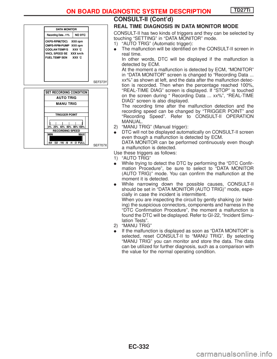
REAL TIME DIAGNOSIS IN DATA MONITOR MODE
CONSULT-II has two kinds of triggers and they can be selected by
touching ªSETTINGº in ªDATA MONITORº mode.
1) ªAUTO TRIGº (Automatic trigger):
IThe malfunction will be identified on the CONSULT-II screen in
real time.
In other words, DTC will be displayed if the malfunction is
detected by ECM.
At the moment a malfunction is detected by ECM, ªMONITORº
in ªDATA MONITORº screen is changed to ªRecording Data ...
xx%º as shown at left, and the data after the malfunction detec-
tion is recorded. Then when the percentage reached 100%,
ªREAL-TIME DIAGº screen is displayed. If ªSTOPº is touched
on the screen during ª Recording Data ... xx%º, ªREAL-TIME
DIAGº screen is also displayed.
The recording time after the malfunction detection and the
recording speed can be changed by ªTRIGGER POINTº and
ªRecording Speedº. Refer to CONSULT-II OPERATION
MANUAL.
2) ªMANU TRIGº (Manual trigger):
IDTC will not be displayed automatically on CONSULT-II screen
even though a malfunction is detected by ECM.
DATA MONITOR can be performed continuously even though
a malfunction is detected.
Use these triggers as follows:
1) ªAUTO TRIGº
IWhile trying to detect the DTC by performing the ªDTC Confir-
mation Procedureº, be sure to select to ªDATA MONITOR
(AUTO TRIG)º mode. You can confirm the malfunction at the
moment it is detected.
IWhile narrowing down the possible causes, CONSULT-II
should be set in ªDATA MONITOR (AUTO TRIG)º mode, espe-
cially in case the incident is intermittent.
When you are inspecting the circuit by gently shaking (or twist-
ing) the suspicious connectors, components and harness in the
ªDTC Confirmation Procedureº, the moment a malfunction is
found the DTC will be displayed. Refer to GI-22, ªIncident Simu-
lation Testsº.
2) ªMANU TRIGº
IIf the malfunction is displayed as soon as ªDATA MONITORº is
selected, reset CONSULT-II to ªMANU TRIGº. By selecting
ªMANU TRIGº you can monitor and store the data. The data
can be utilized for further diagnosis, such as a comparison with
the value for the normal operating condition.
SEF373Y
SEF707X
ON BOARD DIAGNOSTIC SYSTEM DESCRIPTIONTD27Ti
CONSULT-II (Cont'd)
EC-332
Page 699 of 1767
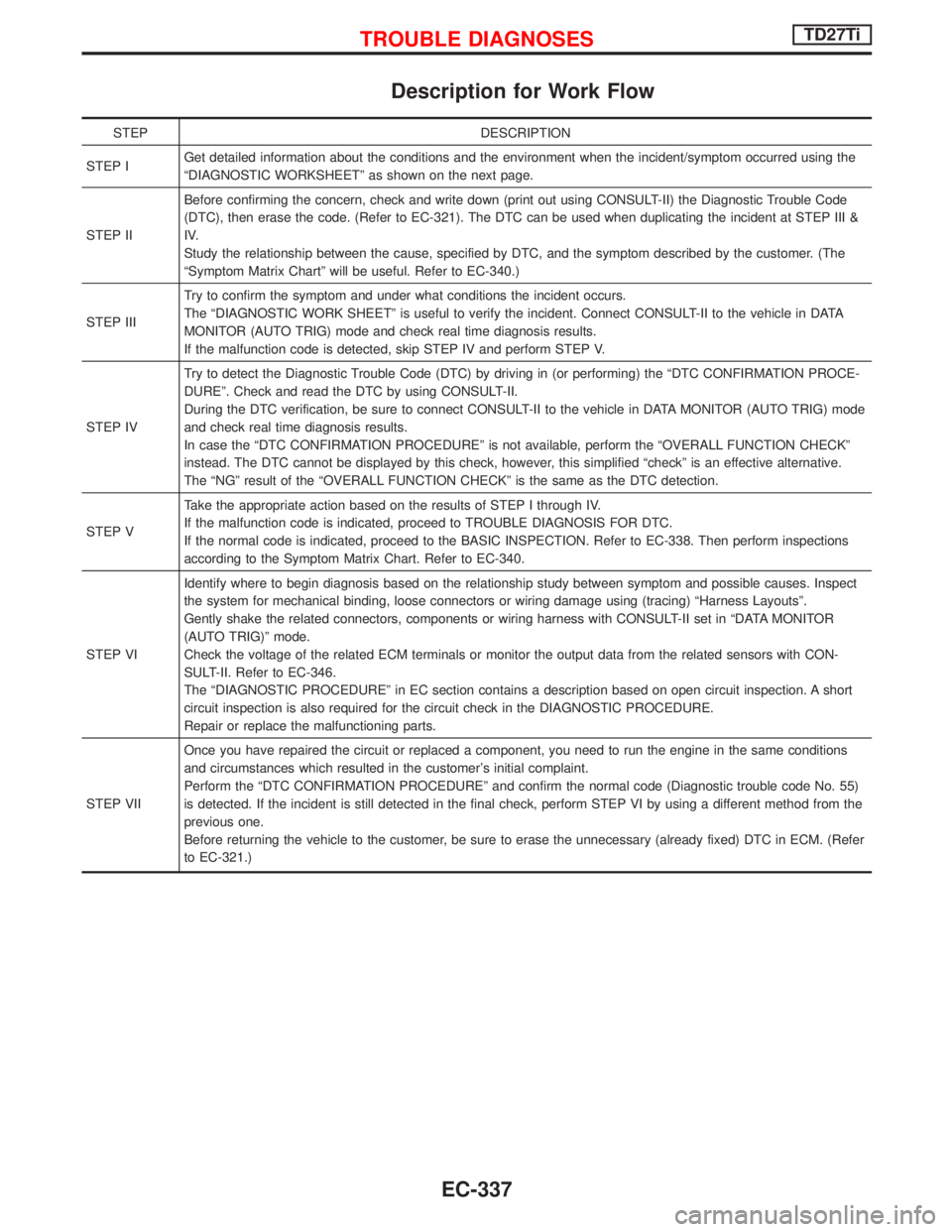
Description for Work Flow
STEP DESCRIPTION
STEP IGet detailed information about the conditions and the environment when the incident/symptom occurred using the
ªDIAGNOSTIC WORKSHEETº as shown on the next page.
STEP IIBefore confirming the concern, check and write down (print out using CONSULT-II) the Diagnostic Trouble Code
(DTC), then erase the code. (Refer to EC-321). The DTC can be used when duplicating the incident at STEP III &
IV.
Study the relationship between the cause, specified by DTC, and the symptom described by the customer. (The
ªSymptom Matrix Chartº will be useful. Refer to EC-340.)
STEP IIITry to confirm the symptom and under what conditions the incident occurs.
The ªDIAGNOSTIC WORK SHEETº is useful to verify the incident. Connect CONSULT-II to the vehicle in DATA
MONITOR (AUTO TRIG) mode and check real time diagnosis results.
If the malfunction code is detected, skip STEP IV and perform STEP V.
STEP IVTry to detect the Diagnostic Trouble Code (DTC) by driving in (or performing) the ªDTC CONFIRMATION PROCE-
DUREº. Check and read the DTC by using CONSULT-II.
During the DTC verification, be sure to connect CONSULT-II to the vehicle in DATA MONITOR (AUTO TRIG) mode
and check real time diagnosis results.
In case the ªDTC CONFIRMATION PROCEDUREº is not available, perform the ªOVERALL FUNCTION CHECKº
instead. The DTC cannot be displayed by this check, however, this simplified ªcheckº is an effective alternative.
The ªNGº result of the ªOVERALL FUNCTION CHECKº is the same as the DTC detection.
STEP VTake the appropriate action based on the results of STEP I through IV.
If the malfunction code is indicated, proceed to TROUBLE DIAGNOSIS FOR DTC.
If the normal code is indicated, proceed to the BASIC INSPECTION. Refer to EC-338. Then perform inspections
according to the Symptom Matrix Chart. Refer to EC-340.
STEP VIIdentify where to begin diagnosis based on the relationship study between symptom and possible causes. Inspect
the system for mechanical binding, loose connectors or wiring damage using (tracing) ªHarness Layoutsº.
Gently shake the related connectors, components or wiring harness with CONSULT-II set in ªDATA MONITOR
(AUTO TRIG)º mode.
Check the voltage of the related ECM terminals or monitor the output data from the related sensors with CON-
SULT-II. Refer to EC-346.
The ªDIAGNOSTIC PROCEDUREº in EC section contains a description based on open circuit inspection. A short
circuit inspection is also required for the circuit check in the DIAGNOSTIC PROCEDURE.
Repair or replace the malfunctioning parts.
STEP VIIOnce you have repaired the circuit or replaced a component, you need to run the engine in the same conditions
and circumstances which resulted in the customer's initial complaint.
Perform the ªDTC CONFIRMATION PROCEDUREº and confirm the normal code (Diagnostic trouble code No. 55)
is detected. If the incident is still detected in the final check, perform STEP VI by using a different method from the
previous one.
Before returning the vehicle to the customer, be sure to erase the unnecessary (already fixed) DTC in ECM. (Refer
to EC-321.)
TROUBLE DIAGNOSESTD27Ti
EC-337
Page 701 of 1767
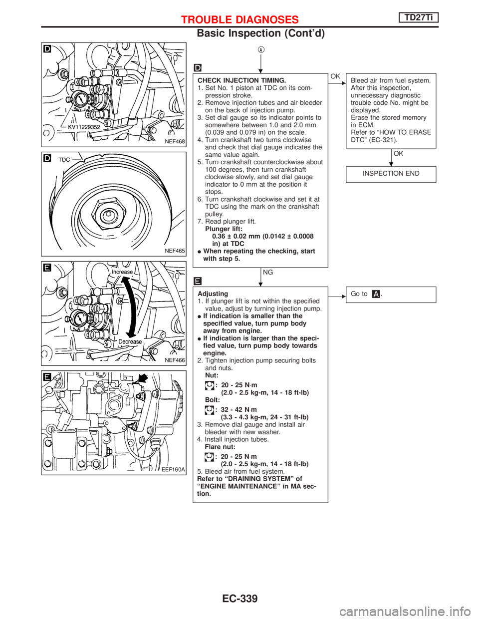
qA
CHECK INJECTION TIMING.
1. Set No. 1 piston at TDC on its com-
pression stroke.
2. Remove injection tubes and air bleeder
on the back of injection pump.
3. Set dial gauge so its indicator points to
somewhere between 1.0 and 2.0 mm
(0.039 and 0.079 in) on the scale.
4. Turn crankshaft two turns clockwise
and check that dial gauge indicates the
same value again.
5. Turn crankshaft counterclockwise about
100 degrees, then turn crankshaft
clockwise slowly, and set dial gauge
indicator to 0 mm at the position it
stops.
6. Turn crankshaft clockwise and set it at
TDC using the mark on the crankshaft
pulley.
7. Read plunger lift.
Plunger lift:
0.36 0.02 mm (0.0142 0.0008
in) at TDC
IWhen repeating the checking, start
with step 5.
NG
EOK
Bleed air from fuel system.
After this inspection,
unnecessary diagnostic
trouble code No. might be
displayed.
Erase the stored memory
in ECM.
Refer to ªHOW TO ERASE
DTCº (EC-321).
OK
INSPECTION END
Adjusting
1. If plunger lift is not within the specified
value, adjust by turning injection pump.
IIf indication is smaller than the
specified value, turn pump body
away from engine.
IIf indication is larger than the speci-
fied value, turn pump body towards
engine.
2. Tighten injection pump securing bolts
and nuts.
Nut:
: 20-25N×m
(2.0 - 2.5 kg-m, 14 - 18 ft-lb)
Bolt:
: 32-42N×m
(3.3 - 4.3 kg-m, 24 - 31 ft-lb)
3. Remove dial gauge and install air
bleeder with new washer.
4. Install injection tubes.
Flare nut:
: 20-25N×m
(2.0 - 2.5 kg-m, 14 - 18 ft-lb)
5. Bleed air from fuel system.
Refer to ªDRAINING SYSTEMº of
ªENGINE MAINTENANCEº in MA sec-
tion.
EGo to.
NEF468
NEF465
NEF466
EEF160A
H
H
H
TROUBLE DIAGNOSESTD27Ti
Basic Inspection (Cont'd)
EC-339