2002 NISSAN TERRANO display
[x] Cancel search: displayPage 893 of 1767

Check items Display Remarks
I) Fuel warning lamp test
SEL443X
Fuel warning lamp is on and odo trip meter segment ªFUELº
flashes.
Failure Chart for ªError 1º and ªError Eº
Bit Detectable items Description of the failureDisplayed figure on the
bit
Failure No failure
0Speedometer input
signalNo input signal
When no signal is detected for 30 minutes continuously with
the ignition ON, it should be judged as signal failure.
(If input signal is detected later, then the judgement will be
canceled immediately.)1
0
Abnormal input signal
When any signal of frequency which would not exist in normal
conditions is detected, it should be judged as signal failure.2
1Tachometer input
signalNo input signal
When no signal is detected for 30 minutes continuously with
the ignition ON, it should be judged as signal failure.
(If input signal is detected later, then the judgement will be
canceled immediately.)1
0
Abnormal input signal
When any signal of frequency which would not exist in normal
conditions is detected, it should be judged as signal failure.2
2Fuel level input sig-
nalShort circuit
When short circuit of the signal line is detected for 5 seconds
or more, it should be judged as short-circuit failure.1
0
Open circuit
When open circuit of the signal line is detected for 5 seconds
or more, it should be judged as open-circuit failure.2
3Water temperature
input signalShort circuit
When short circuit of the signal line is detected for 5 seconds
or more, it should be judged as short-circuit failure.10
4Outside air tempera-
ture input signalShort circuit
When short circuit of the signal line is detected for 5 seconds
or more, it should be judged as short-circuit failure.1
0
Open circuit
When open circuit of the signal line is detected for 5 seconds
or more, it should be judged as open-circuit failure.2
5Reset buttons Short circuit for reset buttons
When the short circuit is continu-
ously detected for 5 minutes or
more, it should be judged as
short-circuit failure.Right side reset button has
failed.1
0 Left side reset button has
failed.2
Both reset buttons have
failed.3
6Ð Ð 00
7CPU EEPROM failure 1
0
CPU RAM failure 2
METER AND GAUGES
Combination Meter Self-Diagnosis (Cont'd)
EL-77
Page 927 of 1767
System Description
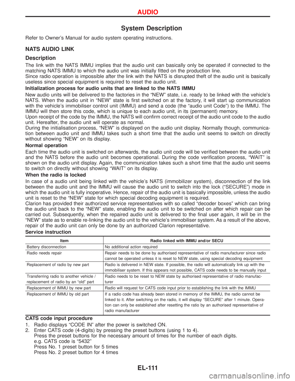
Refer to Owner's Manual for audio system operating instructions.
NATS AUDIO LINK
Description
The link with the NATS IMMU implies that the audio unit can basically only be operated if connected to the
matching NATS IMMU to which the audio unit was initially fitted on the production line.
Since radio operation is impossible after the link with the NATS is disrupted theft of the audio unit is basically
useless since special equipment is required to reset the audio unit.
Initialization process for audio units that are linked to the NATS IMMU
New audio units will be delivered to the factories in the ªNEWº state, i.e. ready to be linked with the vehicle's
NATS. When the audio unit in ªNEWº state is first switched on at the factory, it will start up communication
with the vehicle's immobiliser control unit (IMMU) and send a code (the ªaudio unit Codeº) to the IMMU. The
IMMU will then store this code, which is unique to each audio unit, in its (permanent) memory.
Upon receipt of the code by the IMMU, the NATS will confirm correct receipt of the audio unit code to the audio
unit. Hereafter, the audio unit will operate as normal.
During the initialisation process, ªNEWº is displayed on the audio unit display. Normally though, communica-
tion between audio unit and IMMU takes such a short time that the audio unit seems to switch on directly
without showing ªNEWº on its display.
Normal operation
Each time the audio unit is switched on afterwards, the audio unit code will be verified between the audio unit
and the NATS before the audio unit becomes operational. During the code verification process, ªWAITº is
shown on the audio unit display. Again, the communication takes such a short time that the audio unit seems
to switch on directly without showing ªWAITº on its display.
When the radio is locked
In case of a audio unit being linked with the vehicle's NATS (immobilizer system), disconnection of the link
between the audio unit and the IMMU will cause the audio unit to switch into the lock (ªSECUREº) mode in
which the audio unit is fully inoperative. Hence, repair of the audio unit is basically impossible, unless the audio
unit is reset to the ªNEWº state for which special decoding equipment is required.
Clarion has provided their authorized service representatives with so called ªdecoder boxesº which can bring
the audio unit back to the ªNEWº state, enabling the audio unit to be switched on after which repair can be
carried out. Subsequently, when the repaired audio unit is delivered to the final user again, it will be in the
ªNEWº state as to enable re-linking the audio unit to the vehicle's immobiliser system. As a result of the above,
repair of the audio unit can only be done by an authorized Clarion representative.
Service instruction
Item Radio linked with IMMU and/or SECU
Battery disconnection No additional action required
Radio needs repair Repair needs to be done by authorised representative of radio manufacturer since radio
cannot be operated unless it is reset to NEW state, using special decoding equipment
Replacement of radio by new part Radio is delivered in NEW state. If possible, the radio will automatically link up with the
immobiliser system. If this appears not possible, CATS code needs to be manually input
Transferring radio to another vehicle /
replacement of radio by an ªoldº partRadio needs to be reset to NEW state by authorised representative of radio manufac-
turer
Replacement of IMMU by new part Radio will request for CATS code input prior to establishing the link with the IMMU
Replacement of IMMU by old part If a radio code has already been stored in memory of the IMMU, the radio cannot be
linked to it. After switching on the radio, it will display ªSECUREº after 1 minute. Opera-
tion can only be established after resetting the ratio by an authorised representative of
radio manufacturer
CATS code input procedure
1. Radio displays ªCODE INº after the power is switched ON.
2. Enter CATS code (4-digits) by pressing the preset buttons (using 1 to 4).
Press the preset buttons for the necessary amount of times for the number of each digits.
e.g. CATS code is ª5432º
Press No. 1 preset button for 5 times
Press No. 2 preset button for 4 times
AUDIO
EL-111
Page 928 of 1767

Press No. 3 preset button for 3 times
Press No. 4 preset button for 2 times
3. Press the
button.
4. If the code is OK, the radio will power ON.
If the code is NG, the radio will be locked up as below. After the lock up, the radio will display ªCODE INº
again.
1st to 3rd attempt: The radio will be locked for 10 seconds after each attempt
4th to 20th attempt: The radio will be locked for 60 minutes after each attempt
Over 20th attempt: The radio will be locked completely
AUDIO
System Description (Cont'd)
EL-112
Page 940 of 1767
Trouble Diagnoses
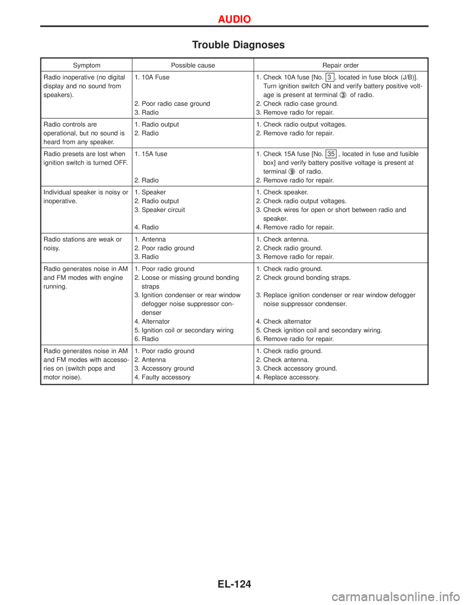
Symptom Possible cause Repair order
Radio inoperative (no digital
display and no sound from
speakers).1. 10A Fuse
2. Poor radio case ground
3. Radio1. Check 10A fuse [No.
3 , located in fuse block (J/B)].
Turn ignition switch ON and verify battery positive volt-
age is present at terminalq
3of radio.
2. Check radio case ground.
3. Remove radio for repair.
Radio controls are
operational, but no sound is
heard from any speaker.1. Radio output
2. Radio1. Check radio output voltages.
2. Remove radio for repair.
Radio presets are lost when
ignition switch is turned OFF.1. 15A fuse
2. Radio1. Check 15A fuse [No.
35 , located in fuse and fusible
box] and verify battery positive voltage is present at
terminalq
9of radio.
2. Remove radio for repair.
Individual speaker is noisy or
inoperative.1. Speaker
2. Radio output
3. Speaker circuit
4. Radio1. Check speaker.
2. Check radio output voltages.
3. Check wires for open or short between radio and
speaker.
4. Remove radio for repair.
Radio stations are weak or
noisy.1. Antenna
2. Poor radio ground
3. Radio1. Check antenna.
2. Check radio ground.
3. Remove radio for repair.
Radio generates noise in AM
and FM modes with engine
running.1. Poor radio ground
2. Loose or missing ground bonding
straps
3. Ignition condenser or rear window
defogger noise suppressor con-
denser
4. Alternator
5. Ignition coil or secondary wiring
6. Radio1. Check radio ground.
2. Check ground bonding straps.
3. Replace ignition condenser or rear window defogger
noise suppressor condenser.
4. Check alternator
5. Check ignition coil and secondary wiring.
6. Remove radio for repair.
Radio generates noise in AM
and FM modes with accesso-
ries on (switch pops and
motor noise).1. Poor radio ground
2. Antenna
3. Accessory ground
4. Faulty accessory1. Check radio ground.
2. Check antenna.
3. Check accessory ground.
4. Replace accessory.
AUDIO
EL-124
Page 1011 of 1767
Trouble Diagnoses
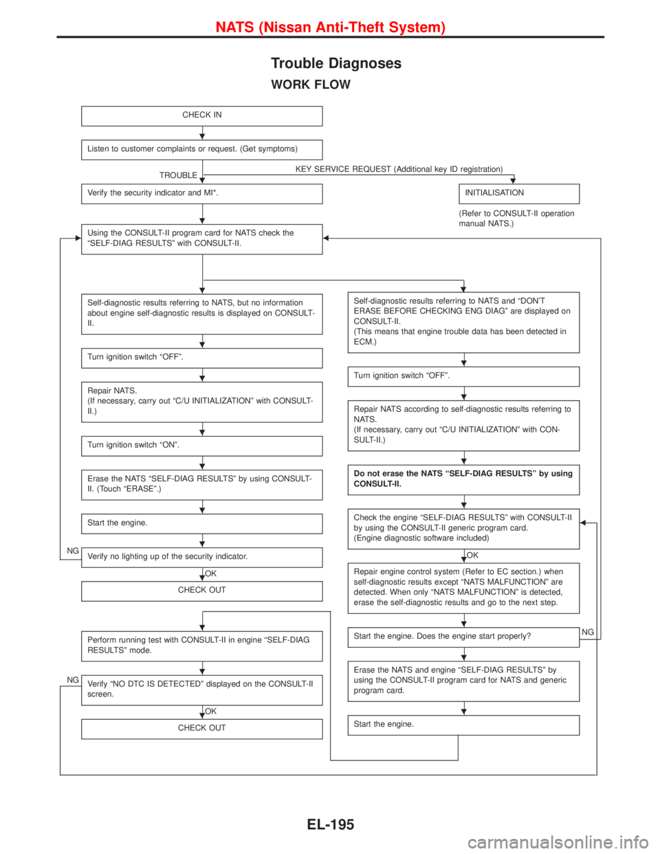
WORK FLOW
CHECK IN
Listen to customer complaints or request. (Get symptoms)
TROUBLEKEY SERVICE REQUEST (Additional key ID registration)H
Verify the security indicator and MI*.INITIALISATION
(Refer to CONSULT-II operation
manual NATS.)
EUsing the CONSULT-II program card for NATS check the
ªSELF-DIAG RESULTSº with CONSULT-II.F
Self-diagnostic results referring to NATS, but no information
about engine self-diagnostic results is displayed on CONSULT-
II.
Turn ignition switch ªOFFº.
Repair NATS.
(If necessary, carry out ªC/U INITIALIZATIONº with CONSULT-
II.)
Turn ignition switch ªONº.
Erase the NATS ªSELF-DIAG RESULTSº by using CONSULT-
II. (Touch ªERASEº.)
Start the engine.
NGVerify no lighting up of the security indicator.
OK
CHECK OUT
Perform running test with CONSULT-II in engine ªSELF-DIAG
RESULTSº mode.
NGVerify ªNO DTC IS DETECTEDº displayed on the CONSULT-II
screen.
OK
CHECK OUT
Self-diagnostic results referring to NATS and ªDON'T
ERASE BEFORE CHECKING ENG DIAGº are displayed on
CONSULT-II.
(This means that engine trouble data has been detected in
ECM.)
Turn ignition switch ªOFFº.
Repair NATS according to self-diagnostic results referring to
NATS.
(If necessary, carry out ªC/U INITIALIZATIONº with CON-
SULT-II.)
Do not erase the NATS ªSELF-DIAG RESULTSº by using
CONSULT-II.
Check the engine ªSELF-DIAG RESULTSº with CONSULT-II
by using the CONSULT-II generic program card.
(Engine diagnostic software included)
OK
F
Repair engine control system (Refer to EC section.) when
self-diagnostic results except ªNATS MALFUNCTIONº are
detected. When only ªNATS MALFUNCTIONº is detected,
erase the self-diagnostic results and go to the next step.
Start the engine. Does the engine start properly?NG
Erase the NATS and engine ªSELF-DIAG RESULTSº by
using the CONSULT-II program card for NATS and generic
program card.
Start the engine.
H
H
H
HH
H
H
H
H
H
H
H
H
H
H
H
H
H
H
H
H
H
H
NATS (Nissan Anti-Theft System)
EL-195
Page 1012 of 1767
SYMPTOM MATRIX CHART 1
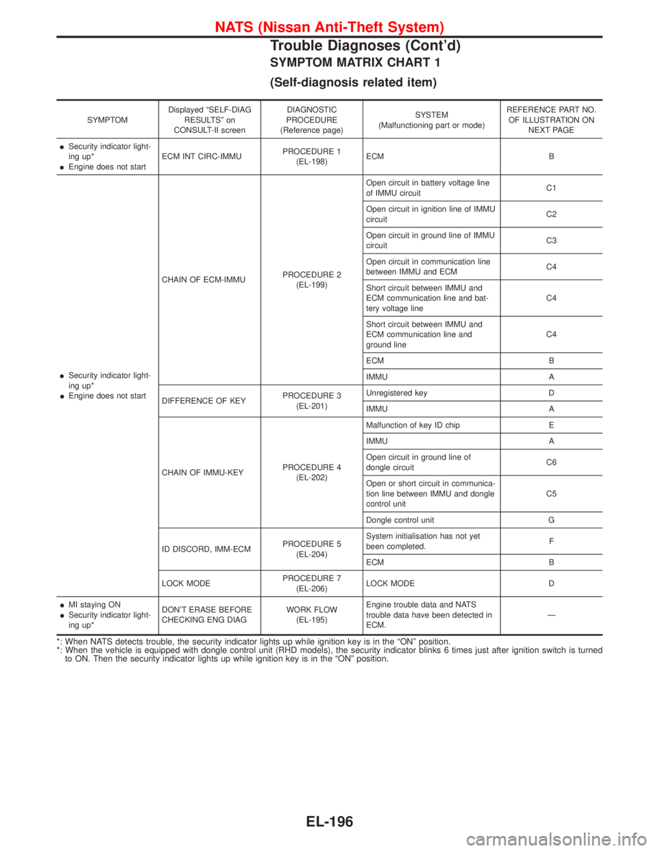
(Self-diagnosis related item)
SYMPTOMDisplayed ªSELF-DIAG
RESULTSº on
CONSULT-II screenDIAGNOSTIC
PROCEDURE
(Reference page)SYSTEM
(Malfunctioning part or mode)REFERENCE PART NO.
OF ILLUSTRATION ON
NEXT PAGE
ISecurity indicator light-
ing up*
IEngine does not startECM INT CIRC-IMMUPROCEDURE 1
(EL-198)ECM B
ISecurity indicator light-
ing up*
IEngine does not startCHAIN OF ECM-IMMUPROCEDURE 2
(EL-199)Open circuit in battery voltage line
of IMMU circuitC1
Open circuit in ignition line of IMMU
circuitC2
Open circuit in ground line of IMMU
circuitC3
Open circuit in communication line
between IMMU and ECMC4
Short circuit between IMMU and
ECM communication line and bat-
tery voltage lineC4
Short circuit between IMMU and
ECM communication line and
ground lineC4
ECM B
IMMU A
DIFFERENCE OF KEYPROCEDURE 3
(EL-201)Unregistered key D
IMMU A
CHAIN OF IMMU-KEYPROCEDURE 4
(EL-202)Malfunction of key ID chip E
IMMU A
Open circuit in ground line of
dongle circuitC6
Open or short circuit in communica-
tion line between IMMU and dongle
control unitC5
Dongle control unit G
ID DISCORD, IMM-ECMPROCEDURE 5
(EL-204)System initialisation has not yet
been completed.F
ECM B
LOCK MODEPROCEDURE 7
(EL-206)LOCK MODE D
IMI staying ON
ISecurity indicator light-
ing up*DON'T ERASE BEFORE
CHECKING ENG DIAGWORK FLOW
(EL-195)Engine trouble data and NATS
trouble data have been detected in
ECM.Ð
*: When NATS detects trouble, the security indicator lights up while ignition key is in the ªONº position.
*: When the vehicle is equipped with dongle control unit (RHD models), the security indicator blinks 6 times just after ignition switch is turned
to ON. Then the security indicator lights up while ignition key is in the ªONº position.
NATS (Nissan Anti-Theft System)
Trouble Diagnoses (Cont'd)
EL-196
Page 1014 of 1767
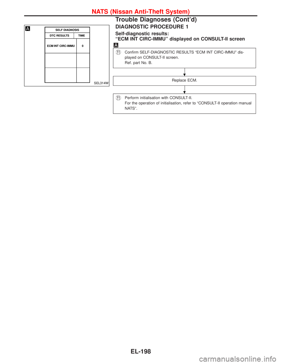
DIAGNOSTIC PROCEDURE 1
Self-diagnostic results:
ªECM INT CIRC-IMMUº displayed on CONSULT-II screen
Confirm SELF-DIAGNOSTIC RESULTS ªECM INT CIRC-IMMUº dis-
played on CONSULT-II screen.
Ref. part No. B.
Replace ECM.
Perform initialisation with CONSULT-II.
For the operation of initialisation, refer to ªCONSULT-II operation manual
NATSº.
SEL314W
H
H
NATS (Nissan Anti-Theft System)
Trouble Diagnoses (Cont'd)
EL-198
Page 1015 of 1767
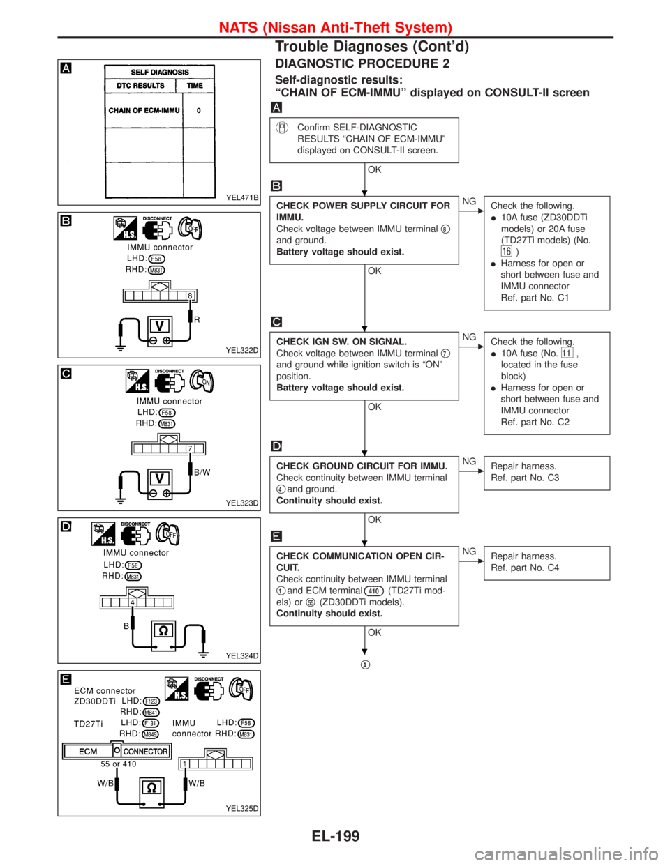
DIAGNOSTIC PROCEDURE 2
Self-diagnostic results:
ªCHAIN OF ECM-IMMUº displayed on CONSULT-II screen
Confirm SELF-DIAGNOSTIC
RESULTS ªCHAIN OF ECM-IMMUº
displayed on CONSULT-II screen.
OK
CHECK POWER SUPPLY CIRCUIT FOR
IMMU.
Check voltage between IMMU terminalq
8
and ground.
Battery voltage should exist.
OK
ENG
Check the following.
I10A fuse (ZD30DDTi
models) or 20A fuse
(TD27Ti models) (No.
16)
IHarness for open or
short between fuse and
IMMU connector
Ref. part No. C1
CHECK IGN SW. ON SIGNAL.
Check voltage between IMMU terminalq
7
and ground while ignition switch is ªONº
position.
Battery voltage should exist.
OK
ENG
Check the following.
I10A fuse (No.
11 ,
located in the fuse
block)
IHarness for open or
short between fuse and
IMMU connector
Ref. part No. C2
CHECK GROUND CIRCUIT FOR IMMU.
Check continuity between IMMU terminal
q
4and ground.
Continuity should exist.
OK
ENG
Repair harness.
Ref. part No. C3
CHECK COMMUNICATION OPEN CIR-
CUIT.
Check continuity between IMMU terminal
q
1and ECM terminal410(TD27Ti mod-
els) orq
55(ZD30DDTi models).
Continuity should exist.
OK
ENG
Repair harness.
Ref. part No. C4
qA
YEL471B
YEL322D
YEL323D
YEL324D
YEL325D
H
H
H
H
H
NATS (Nissan Anti-Theft System)
Trouble Diagnoses (Cont'd)
EL-199