2002 NISSAN TERRANO seats
[x] Cancel search: seatsPage 1118 of 1767
1. Warm up engine.
2. Turn ignition switch OFF.
3. Using CONSULT-II, make sure no error codes are indicated for
self-diagnosis items. Refer to EC section, ªFuel Pressure
Releaseº.
IDo not disconnect CONSULT-II until the end of this operation;
it will be used to check engine rpm and for error detection at
the end of this operation.
4. Disconnect the negative battery terminal.
5. Remove the following parts.
IIntercooler
IThrottle body
IRocker cover
6. To prevent fuel from being injected during inspection, remove
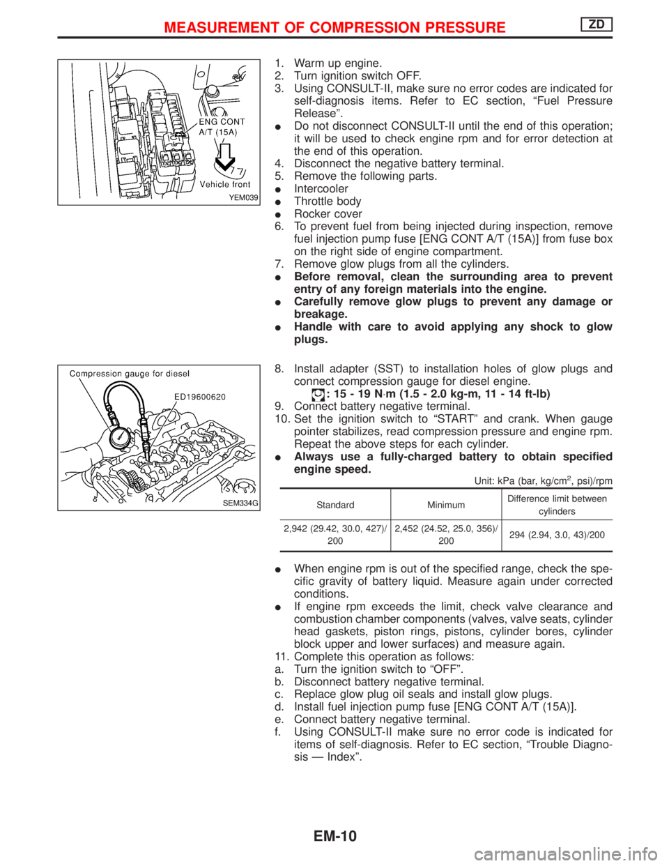
fuel injection pump fuse [ENG CONT A/T (15A)] from fuse box
on the right side of engine compartment.
7. Remove glow plugs from all the cylinders.
IBefore removal, clean the surrounding area to prevent
entry of any foreign materials into the engine.
ICarefully remove glow plugs to prevent any damage or
breakage.
IHandle with care to avoid applying any shock to glow
plugs.
8. Install adapter (SST) to installation holes of glow plugs and
connect compression gauge for diesel engine.
:15-19N×m (1.5 - 2.0 kg-m, 11 - 14 ft-lb)
9. Connect battery negative terminal.
10. Set the ignition switch to ªSTARTº and crank. When gauge
pointer stabilizes, read compression pressure and engine rpm.
Repeat the above steps for each cylinder.
IAlways use a fully-charged battery to obtain specified
engine speed.
Unit: kPa (bar, kg/cm2, psi)/rpm
Standard MinimumDifference limit between
cylinders
2,942 (29.42, 30.0, 427)/
2002,452 (24.52, 25.0, 356)/
200294 (2.94, 3.0, 43)/200
IWhen engine rpm is out of the specified range, check the spe-
cific gravity of battery liquid. Measure again under corrected
conditions.
IIf engine rpm exceeds the limit, check valve clearance and
combustion chamber components (valves, valve seats, cylinder
head gaskets, piston rings, pistons, cylinder bores, cylinder
block upper and lower surfaces) and measure again.
11. Complete this operation as follows:
a. Turn the ignition switch to ªOFFº.
b. Disconnect battery negative terminal.
c. Replace glow plug oil seals and install glow plugs.
d. Install fuel injection pump fuse [ENG CONT A/T (15A)].
e. Connect battery negative terminal.
f. Using CONSULT-II make sure no error code is indicated for
items of self-diagnosis. Refer to EC section, ªTrouble Diagno-
sis Ð Indexº.
YEM039
SEM334G
MEASUREMENT OF COMPRESSION PRESSUREZD
EM-10
Page 1158 of 1767
VALVE OIL SEAL
1. Remove timing chain. Refer to EM-26, ªTIMING CHAINº.
2. Remove injection nozzle assembly. Refer to ªInjection Tube and
Injection Nozzleº in ªBASIC SERVICE PROCEDUREº in EC
section.
3. Remove camshaft. Refer to EM-30, ªCAMSHAFTº.
4. Remove valve lifters and mark order No. on each lifter.
5. Replace valve oil seal according to the following procedure.
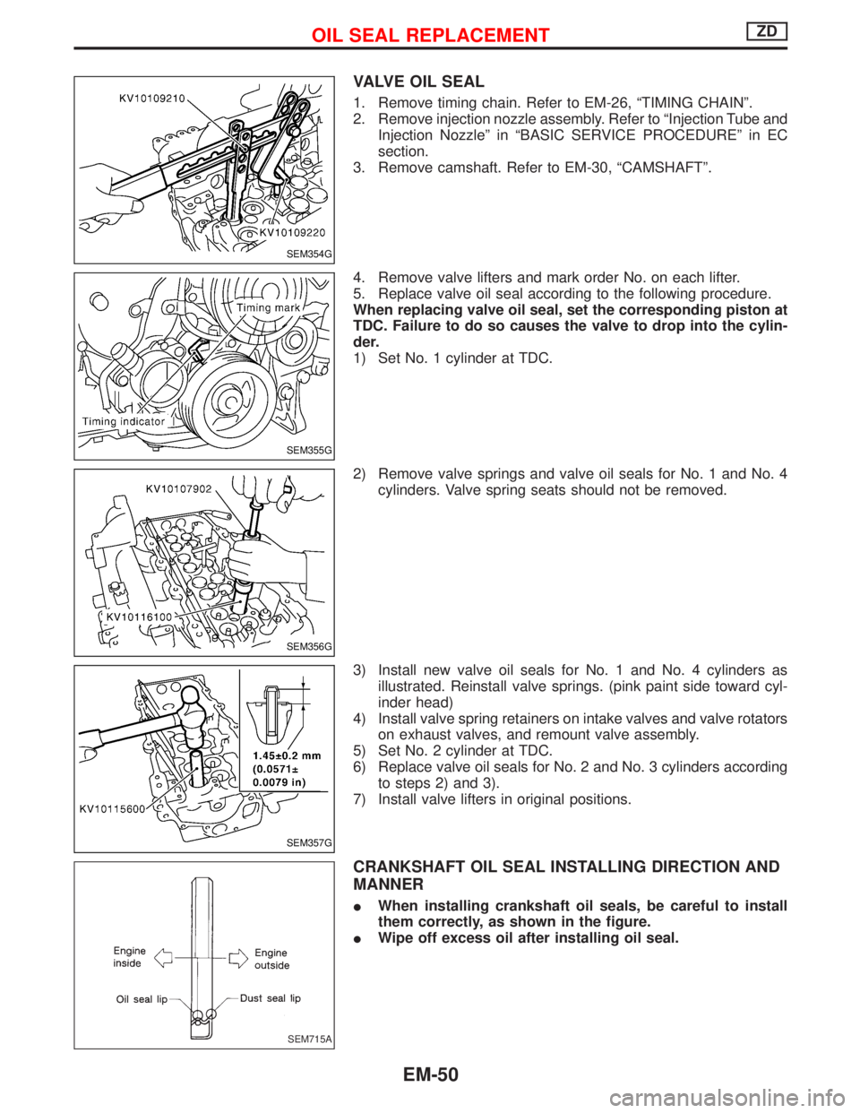
When replacing valve oil seal, set the corresponding piston at
TDC. Failure to do so causes the valve to drop into the cylin-
der.
1) Set No. 1 cylinder at TDC.
2) Remove valve springs and valve oil seals for No. 1 and No. 4
cylinders. Valve spring seats should not be removed.
3) Install new valve oil seals for No. 1 and No. 4 cylinders as
illustrated. Reinstall valve springs. (pink paint side toward cyl-
inder head)
4) Install valve spring retainers on intake valves and valve rotators
on exhaust valves, and remount valve assembly.
5) Set No. 2 cylinder at TDC.
6) Replace valve oil seals for No. 2 and No. 3 cylinders according
to steps 2) and 3).
7) Install valve lifters in original positions.
CRANKSHAFT OIL SEAL INSTALLING DIRECTION AND
MANNER
IWhen installing crankshaft oil seals, be careful to install
them correctly, as shown in the figure.
IWipe off excess oil after installing oil seal.
SEM354G
SEM355G
SEM356G
SEM357G
SEM715A
OIL SEAL REPLACEMENTZD
EM-50
Page 1166 of 1767
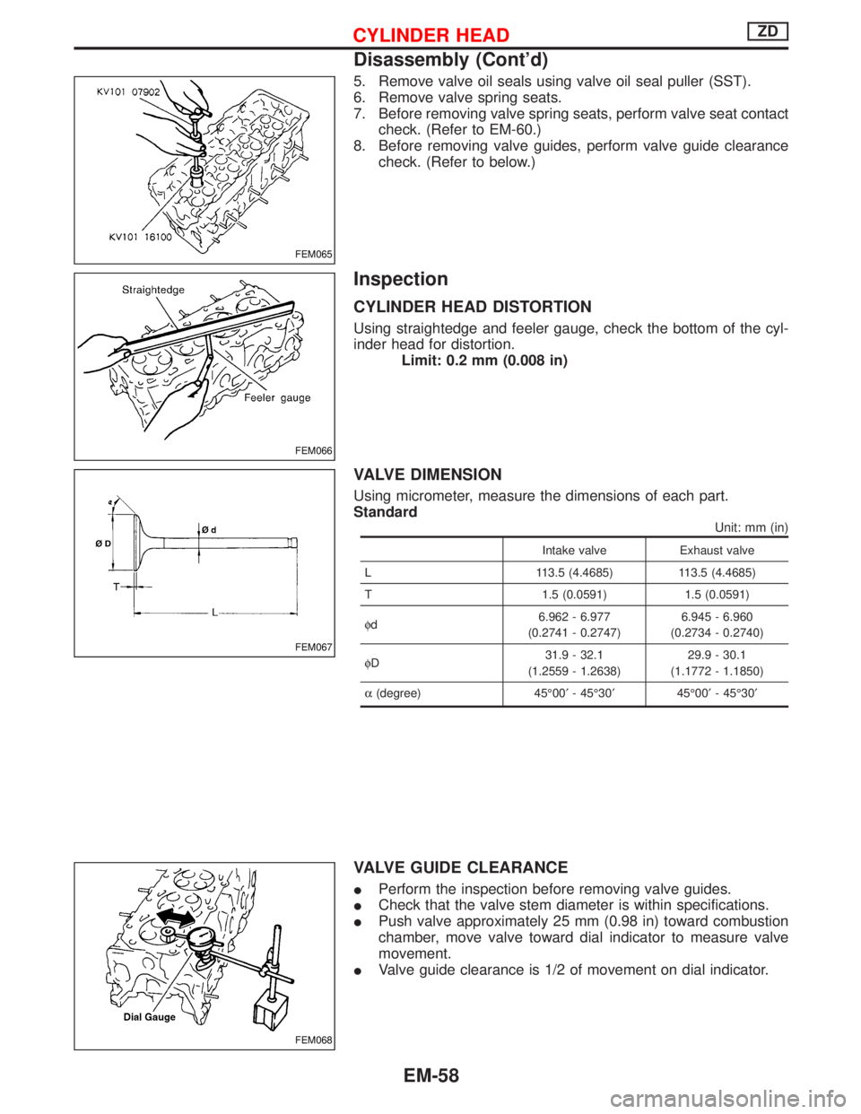
5. Remove valve oil seals using valve oil seal puller (SST).
6. Remove valve spring seats.
7. Before removing valve spring seats, perform valve seat contact
check. (Refer to EM-60.)
8. Before removing valve guides, perform valve guide clearance
check. (Refer to below.)
Inspection
CYLINDER HEAD DISTORTION
Using straightedge and feeler gauge, check the bottom of the cyl-
inder head for distortion.
Limit: 0.2 mm (0.008 in)
VALVE DIMENSION
Using micrometer, measure the dimensions of each part.
Standard
Unit: mm (in)
Intake valve Exhaust valve
L 113.5 (4.4685) 113.5 (4.4685)
T 1.5 (0.0591) 1.5 (0.0591)
fd6.962 - 6.977
(0.2741 - 0.2747)6.945 - 6.960
(0.2734 - 0.2740)
fD31.9 - 32.1
(1.2559 - 1.2638)29.9 - 30.1
(1.1772 - 1.1850)
a(degree) 45É00¢- 45É30¢45É00¢- 45É30¢
VALVE GUIDE CLEARANCE
IPerform the inspection before removing valve guides.
ICheck that the valve stem diameter is within specifications.
IPush valve approximately 25 mm (0.98 in) toward combustion
chamber, move valve toward dial indicator to measure valve
movement.
IValve guide clearance is 1/2 of movement on dial indicator.
FEM065
FEM066
FEM067
FEM068
CYLINDER HEADZD
Disassembly (Cont'd)
EM-58
Page 1168 of 1767
VALVE SEAT CONTACT
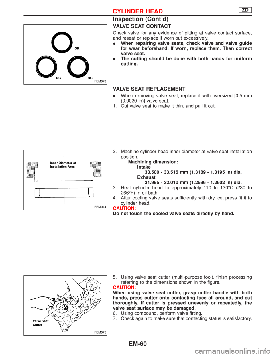
Check valve for any evidence of pitting at valve contact surface,
and reseat or replace if worn out excessively.
IWhen repairing valve seats, check valve and valve guide
for wear beforehand. If worn, replace them. Then correct
valve seat.
IThe cutting should be done with both hands for uniform
cutting.
VALVE SEAT REPLACEMENT
IWhen removing valve seat, replace it with oversized [0.5 mm
(0.0020 in)] valve seat.
1. Cut valve seat to make it thin, and pull it out.
2. Machine cylinder head inner diameter at valve seat installation
position.
Machining dimension:
Intake
33.500 - 33.515 mm (1.3189 - 1.3195 in) dia.
Exhaust
31.995 - 32.010 mm (1.2596 - 1.2602 in) dia.
3. Heat cylinder head to approximately 110 to 130ÉC (230 to
266ÉF) in oil bath.
4. After cooling valve seats sufficiently with dry ice, press fit it to
cylinder head.
CAUTION:
Do not touch the cooled valve seats directly by hand.
5. Using valve seat cutter (multi-purpose tool), finish processing
referring to the dimensions shown in the figure.
CAUTION:
When using valve seat cutter, grasp cutter handle with both
hands, press cutter onto contacting face all around, and cut
thoroughly. If cutter is pressed unevenly or repeatedly, the
valve seat surface may be damaged.
6. Using compound, perform valve fitting.
7. Check again to make sure that contacting status is satisfactory.
FEM073
FEM074
FEM075
CYLINDER HEADZD
Inspection (Cont'd)
EM-60
Page 1169 of 1767
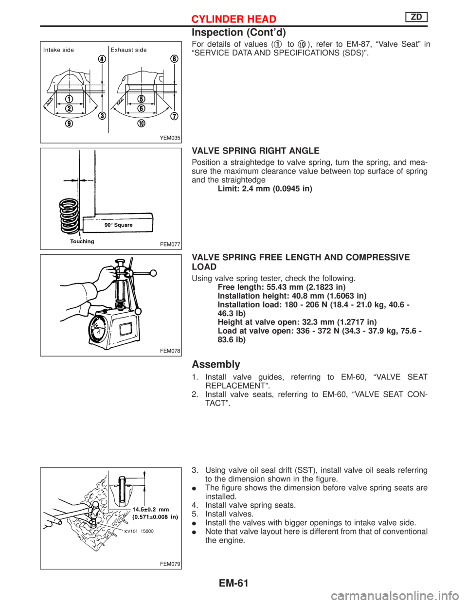
For details of values (q1toq10), refer to EM-87, ªValve Seatº in
ªSERVICE DATA AND SPECIFICATIONS (SDS)º.
VALVE SPRING RIGHT ANGLE
Position a straightedge to valve spring, turn the spring, and mea-
sure the maximum clearance value between top surface of spring
and the straightedge
Limit: 2.4 mm (0.0945 in)
VALVE SPRING FREE LENGTH AND COMPRESSIVE
LOAD
Using valve spring tester, check the following.
Free length: 55.43 mm (2.1823 in)
Installation height: 40.8 mm (1.6063 in)
Installation load: 180 - 206 N (18.4 - 21.0 kg, 40.6 -
46.3 lb)
Height at valve open: 32.3 mm (1.2717 in)
Load at valve open: 336 - 372 N (34.3 - 37.9 kg, 75.6 -
83.6 lb)
Assembly
1. Install valve guides, referring to EM-60, ªVALVE SEAT
REPLACEMENTº.
2. Install valve seats, referring to EM-60, ªVALVE SEAT CON-
TACTº.
3. Using valve oil seal drift (SST), install valve oil seals referring
to the dimension shown in the figure.
IThe figure shows the dimension before valve spring seats are
installed.
4. Install valve spring seats.
5. Install valves.
IInstall the valves with bigger openings to intake valve side.
INote that valve layout here is different from that of conventional
the engine.
YEM035
FEM077
FEM078
FEM079
CYLINDER HEADZD
Inspection (Cont'd)
EM-61
Page 1216 of 1767
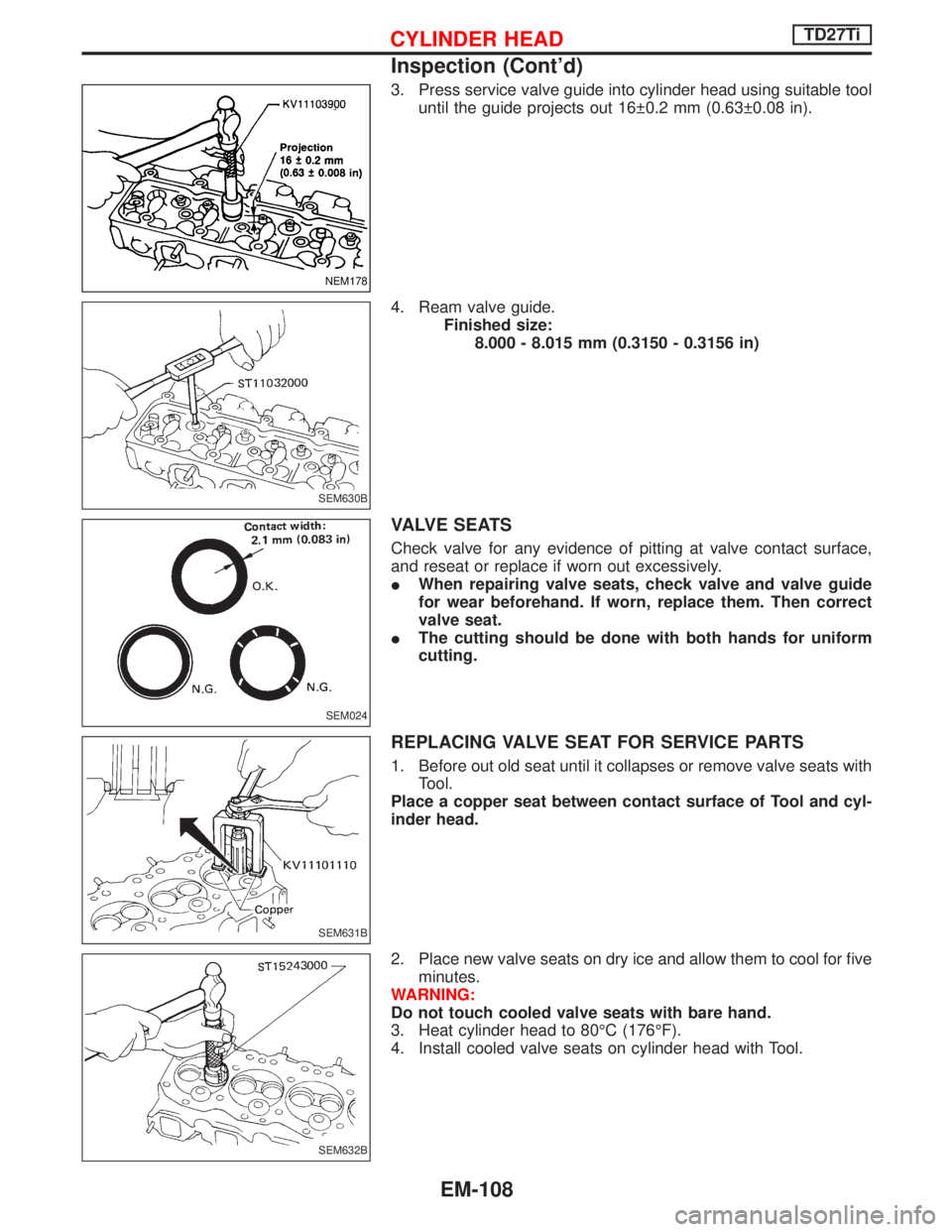
3. Press service valve guide into cylinder head using suitable tool
until the guide projects out 16 0.2 mm (0.63 0.08 in).
4. Ream valve guide.
Finished size:
8.000 - 8.015 mm (0.3150 - 0.3156 in)
VALVE SEATS
Check valve for any evidence of pitting at valve contact surface,
and reseat or replace if worn out excessively.
IWhen repairing valve seats, check valve and valve guide
for wear beforehand. If worn, replace them. Then correct
valve seat.
IThe cutting should be done with both hands for uniform
cutting.
REPLACING VALVE SEAT FOR SERVICE PARTS
1. Before out old seat until it collapses or remove valve seats with
Tool.
Place a copper seat between contact surface of Tool and cyl-
inder head.
2. Place new valve seats on dry ice and allow them to cool for five
minutes.
WARNING:
Do not touch cooled valve seats with bare hand.
3. Heat cylinder head to 80ÉC (176ÉF).
4. Install cooled valve seats on cylinder head with Tool.
NEM178
SEM630B
SEM024
SEM631B
SEM632B
CYLINDER HEADTD27Ti
Inspection (Cont'd)
EM-108
Page 1277 of 1767
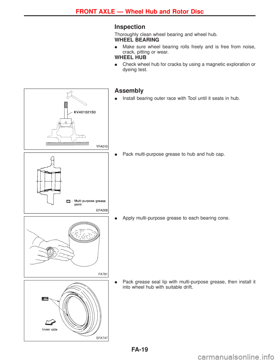
Inspection
Thoroughly clean wheel bearing and wheel hub.
WHEEL BEARING
IMake sure wheel bearing rolls freely and is free from noise,
crack, pitting or wear.
WHEEL HUB
ICheck wheel hub for cracks by using a magnetic exploration or
dyeing test.
Assembly
IInstall bearing outer race with Tool until it seats in hub.
IPack multi-purpose grease to hub and hub cap.
IApply multi-purpose grease to each bearing cone.
IPack grease seal lip with multi-purpose grease, then install it
into wheel hub with suitable drift.
YFA010
EFA008
FA781
SFA747
FRONT AXLE Ð Wheel Hub and Rotor Disc
FA-19
Page 1462 of 1767
Shown below are Pre-delivery Inspection items required for the new vehicle. It is recommended that
necessary items other than those listed here be added, paying due regard to the conditions in each
country.
Perform applicable items on each model. Consult text of this section for specifications.
UNDER HOOD Ð engine off
lRadiator coolant level and coolant hose connections for leaks
lBattery fluid level, specific gravity and conditions of battery terminals
lBrake and clutch reservoirs fluid level and fluid lines for leaks
lWindshield and rear window washer and headlamp cleaner reservoir fluid level
lDrive belts tension
lFuel filter for water or dust, and fuel lines and connections for leaks
lPower steering reservoir fluid level and hose connections for leaks
lEngine oil level and oil leaks
INSIDE AND OUTSIDE
lOperation of all instruments, gauges, lights, anti-theft system and accessories
lOperation of horn(s), wiper and washer
lSteering lock for operation
lAir conditioner for gas leaks
lFront and rear seats, and seat belts for operation
lAll moldings, trims and fittings for fit and alignment
lAll windows for operation and alignment
lHood, tailgate, door panels for fit and alignment
lLatches, keys and locks for operation
lWeatherstrips for adhesion and fit
lHeadlamp aiming
lTighten wheel nuts
lTire pressure (Inc. spare tire)
lCheck front wheels for toe-in
lInstall clock/room lamp fuse
lRemove wiper blade protectors (if necessary)
UNDER BODY
lManual transmission/transaxle and differential gear oil level
lBrake and fuel lines and oil/fluid reservoirs for leaks
lTighten bolts and nuts of steering linkage and gear box, suspension, propeller shafts and drive shafts
ROAD TEST
lClutch operation
lParking brake operation
lService brake operation
lSteering control and returnability
lEngine performance
lSqueaks and rattles
ENGINE OPERATING AND HOT
lAdjust idle mixture and speed (and ignition timing) (Petrol only)
FINAL INSPECTION
lInstall necessary parts (outside mirror, wheel covers, seat belts, mat, carpet or mud flaps)
lInspect for interior and exterior metal and paint damage
lCheck for spare tire, jack, tools and literature
lWash, clean interior and exterior
PRE-DELIVERY INSPECTION ITEMS
MA-3