Page 7 of 1767

Service Notice or Precautions
FAIL-SAFE
The TCM has an electronic Fail-Safe (limp home mode). This allows the vehicle to be driven even if a major
electrical input/output device circuit is damaged.
Under Fail-Safe, the vehicle always runs in third gear even with a shift lever position of ª1º, ª2º or ªDº. Cus-
tomer may complain of ªsluggish or poor accelerationº.
When the Fail-Safe operation occurs the next time the key is turned to the ªONº position, the SPORT indica-
tor lamp will blink for about 8 seconds. (For diagnosis, refer to AT-33.)
Fail-Safe may activate without electrical circuit damages if the vehicle is driven under extreme conditions (such
as excessive wheel spins and emergency braking immediately afterwards). In this case, turn the ignition key
ªOFFº for 5 seconds and then ªONº to recover normal shift pattern.
The blinking of the SPORT indicator lamp for about 8 seconds will appear only once and be cleared. The cus-
tomer may resume normal driving conditions by chance.
Always follow the ªWORK FLOWº (Refer to AT-26).
The SELF-DIAGNOSIS results will be as follows:
The first SELF-DIAGNOSIS will indicate the damage of the vehicle speed sensor or the revolution sensor.
During the next SELF-DIAGNOSIS performed after checking the sensor, no damages will be indicated.
PREPARATION AND PRECAUTIONS
AT- 5
Page 25 of 1767
Diagnostic Worksheet
INFORMATION FROM CUSTOMER
KEY POINTS
WHAT......................... Vehicle & A/T model
WHEN......................... Date, Frequencies
WHERE...................... Road conditions
HOW........................... Operating conditions, Symptoms
Customer name MR/MS Model & Year VIN
Trans. model Engine Mileage
Incident Date Manuf. Date In Service Date
FrequencylContinuouslIntermittent ( times a day)
SymptomslVehicle does not move. (lAny positionlParticular position)
lNo up-shift (l1st,2ndl2nd,3rdl3rd,O/D)
lNo down-shift (lO/D,3rdl3rd,2ndl2nd,1st)
lLockup malfunction
lShift point too high or too low.
lShift shock or slip (lN,DlLockuplAny drive position)
lNoise or vibration
lNo kickdown
lNo pattern select
lOthers
()
SPORT indicator lamp Blinks for about 8 seconds.
lContinuously litlNot lit
Malfunction indicator lamp
(MIL)lContinuously litlNot lit
TROUBLE DIAGNOSIS Ð Introduction
AT-23
Page 95 of 1767

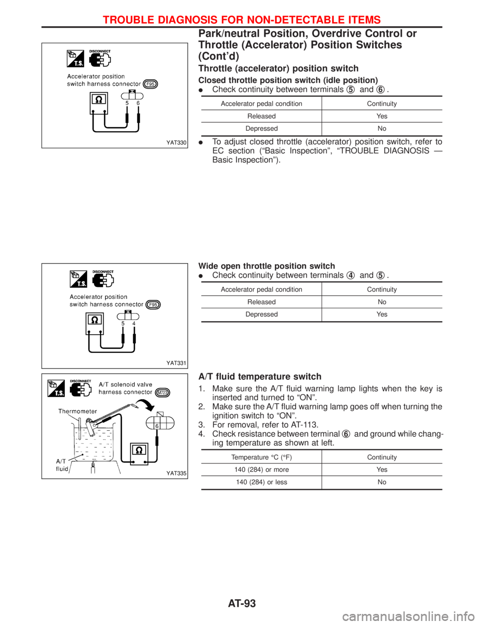
Throttle (accelerator) position switch
Closed throttle position switch (idle position)
ICheck continuity between terminalsq
5andq6.
Accelerator pedal condition Continuity
Released Yes
Depressed No
ITo adjust closed throttle (accelerator) position switch, refer to
EC section (ªBasic Inspectionº, ªTROUBLE DIAGNOSIS Ð
Basic Inspectionº).
Wide open throttle position switch
ICheck continuity between terminalsq
4andq5.
Accelerator pedal condition Continuity
Released No
Depressed Yes
A/T fluid temperature switch
1. Make sure the A/T fluid warning lamp lights when the key is
inserted and turned to ªONº.
2. Make sure the A/T fluid warning lamp goes off when turning the
ignition switch to ªONº.
3. For removal, refer to AT-113.
4. Check resistance between terminalq
6and ground while chang-
ing temperature as shown at left.
Temperature ÉC (ÉF) Continuity
140 (284) or more Yes
140 (284) or less No
YAT330
YAT331
YAT335
TROUBLE DIAGNOSIS FOR NON-DETECTABLE ITEMS
Park/neutral Position, Overdrive Control or
Throttle (Accelerator) Position Switches
(Cont'd)
AT-93
Page 265 of 1767
ACTIVE TEST PROCEDURE
IWhen conducting Active test, vehicle must be stationary.
IWhen ABS warning lamp stays on, never conduct Active test.
1) Turn ignition switch to the ªLOCKº position.
2) Connect CONSULT-II to Data Link Connector.
3) Start engine.
1) Touch ªSTARTº on CONSULT-II screen.
2) Touch ªABSº.
3) Touch ªACTIVE TESTº.
1) Select active test item by touching screen.
2) Touch ªSTARTº.
Carry out the active test by touching screen key.
C2NCS01
C2SSE01
C2SDM01
C2STI01
C2FRS01
H
H
H
TROUBLE DIAGNOSES
CONSULT-II Inspection Procedure (Cont'd)
BR-63
Page 396 of 1767

IIf the battery is disconnected, the emission-related diagnostic information will be lost after approx.
24 hours.
IErasing the emission-related diagnostic information using CONSULT-II is easier and quicker than
switching the diagnostic test mode using the data link connector.
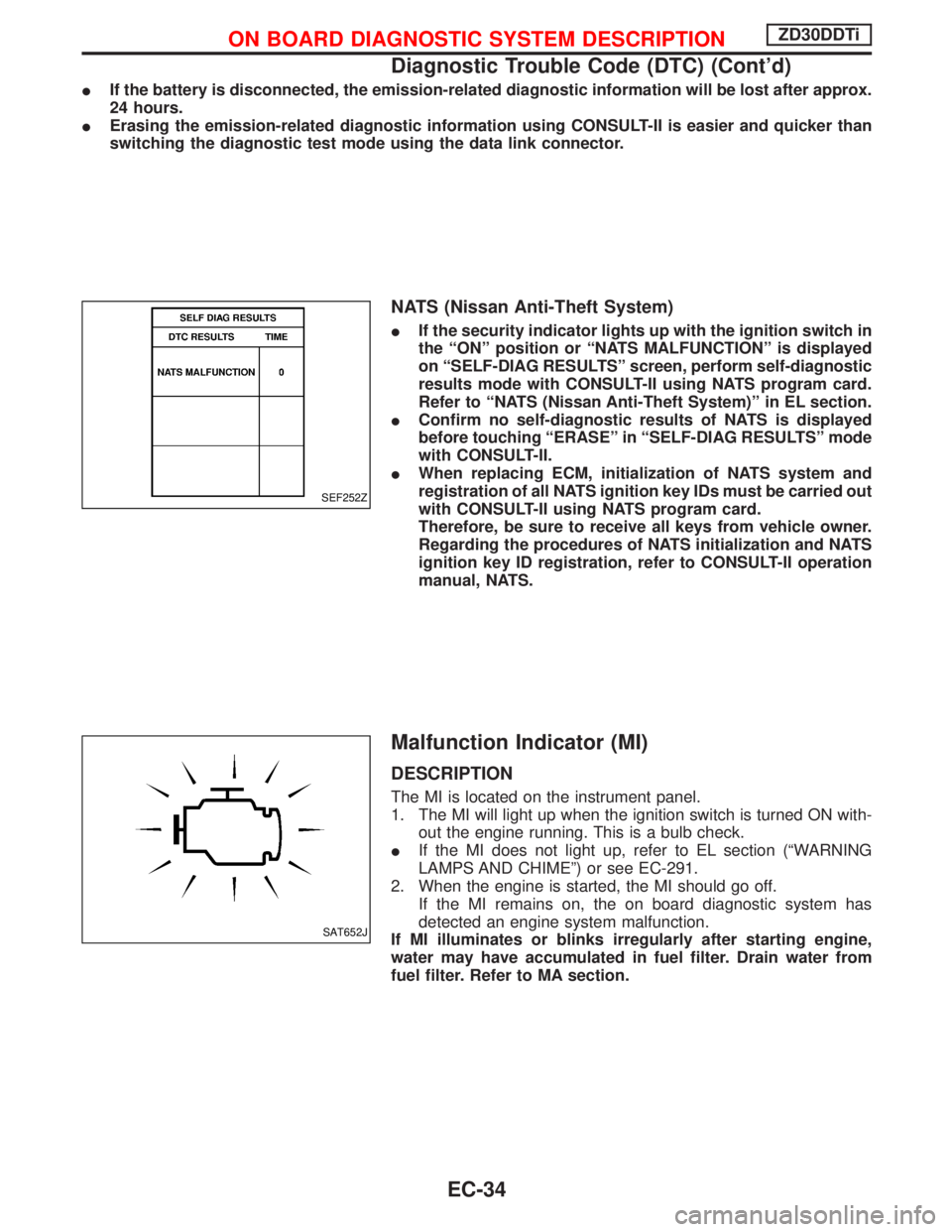
NATS (Nissan Anti-Theft System)
IIf the security indicator lights up with the ignition switch in
the ªONº position or ªNATS MALFUNCTIONº is displayed
on ªSELF-DIAG RESULTSº screen, perform self-diagnostic
results mode with CONSULT-II using NATS program card.
Refer to ªNATS (Nissan Anti-Theft System)º in EL section.
IConfirm no self-diagnostic results of NATS is displayed
before touching ªERASEº in ªSELF-DIAG RESULTSº mode
with CONSULT-II.
IWhen replacing ECM, initialization of NATS system and
registration of all NATS ignition key IDs must be carried out
with CONSULT-II using NATS program card.
Therefore, be sure to receive all keys from vehicle owner.
Regarding the procedures of NATS initialization and NATS
ignition key ID registration, refer to CONSULT-II operation
manual, NATS.
Malfunction Indicator (MI)
DESCRIPTION
The MI is located on the instrument panel.
1. The MI will light up when the ignition switch is turned ON with-
out the engine running. This is a bulb check.
IIf the MI does not light up, refer to EL section (ªWARNING
LAMPS AND CHIMEº) or see EC-291.
2. When the engine is started, the MI should go off.
If the MI remains on, the on board diagnostic system has
detected an engine system malfunction.
If MI illuminates or blinks irregularly after starting engine,
water may have accumulated in fuel filter. Drain water from
fuel filter. Refer to MA section.
SEF252Z
SAT652J
ON BOARD DIAGNOSTIC SYSTEM DESCRIPTIONZD30DDTi
Diagnostic Trouble Code (DTC) (Cont'd)
EC-34
Page 397 of 1767
On board diagnostic system function
The on board diagnostic system has the following three functions.
Diagnostic Test Mode KEY and ENG. Status Function Explanation of Function
Mode I Ignition switch in ON
position
Engine stopped
BULB CHECK This function checks the MI bulb for damage
(blown, open circuit, etc.).
If the MI does not come on, check MI circuit.
(See EC-291.)
Engine running
MALFUNCTION
WARNINGThis is a usual driving condition. When ECM
detects a malfunction, the MI will light up to
inform the driver that a malfunction has been
detected.
Mode II Ignition switch in ON
position
Engine stopped
SELF-DIAGNOSTIC RESULTS This function allows DTCs to be read.
ON BOARD DIAGNOSTIC SYSTEM DESCRIPTIONZD30DDTi
Malfunction Indicator (MI) (Cont'd)
EC-35
Page 680 of 1767
q1Electric fuel injection pump
q
2Key
q
3Bracketq
4Injection pump drive gear
q
5Dust cover
q
6Bracketq
7Gasket
q
8Gasket
Removal
1. Remove battery.
Disconnect electronic injection pump harness connectors.
2. Set No. 1 piston at TDC on its compression stroke.
3. Remove fuel hoses (supply, return and spill) and injection
tubes.
NEF460
EEF181
ELECTRONIC FUEL INJECTION PUMPTD27Ti
EC-318
Page 681 of 1767
4. Remove dust cover and injection pump gear.
Refer to EM section.
5. Remove fixing nuts and bolts. Then remove injection pump.
Installation
Install injection pump assembly in the reverse order of removal,
observing the following:
1. Confirm that No. 1 cylinder is set at TDC on its compression
stroke.
2. Install injection pump (Refer to EM section).
(1) Temporarily set injection pump so that the flange of the pump
is aligned with aligning mark on front cover.
(2) Install injection pump gear.
:59-69N×m (6 - 7 kg-m, 43 - 51 ft-lb)
Make sure that the key does not fall into the front cover.
Make sure that ªZº marks are aligned.
(3) Apply liquid gasket to mating surface of injection pump gear
cover and install it.
3. Adjust injection timing.
Refer to ªBasic Inspectionº, EC-338.
4. Install all parts removed.
SEM653B
EEF160
EEF181
SEF337F
ELECTRONIC FUEL INJECTION PUMPTD27Ti
Removal (Cont'd)
EC-319