2002 NISSAN TERRANO oil change
[x] Cancel search: oil changePage 45 of 1767
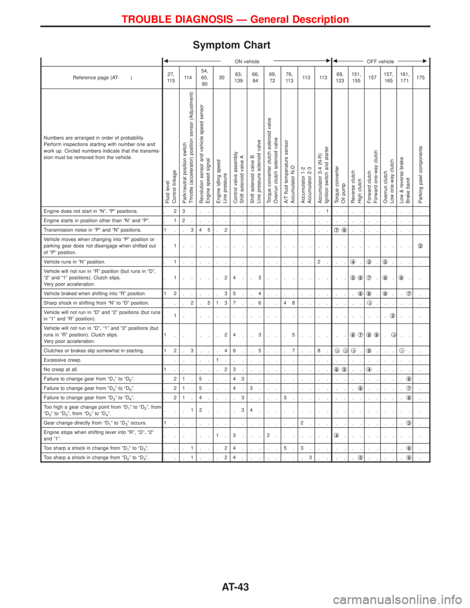
Symptom Chart
FON vehicleEFOFF vehicleE
Reference page (AT- )27,
11 511 454,
60,
803063,
13966,
8469,
7276,
11 311 3 11 369,
123151,
155157157,
165161,
171175
Numbers are arranged in order of probability.
Perform inspections starting with number one and
work up. Circled numbers indicate that the transmis-
sion must be removed from the vehicle.
Fluid level
Control linkage
Park/neutral position switch
Throttle (accelerator) position sensor (Adjustment)
Revolution sensor and vehicle speed sensor
Engine speed signal
Engine idling speed
Line pressure
Control valve assembly
Shift solenoid valve A
Shift solenoid valve B
Line pressure solenoid valve
Torque converter clutch solenoid valve
Overrun clutch solenoid valve
A/T fluid temperature sensor
Accumulator N-D
Accumulator 1-2
Accumulator 2-3
Accumulator 3-4 (N-R)
Ignition switch and starter
Torque converter
Oil pump
Reverse clutch
High clutch
Forward clutch
Forward one-way clutch
Overrun clutch
Low one-way clutch
Low & reverse brake
Brake band
Parking pawl components
Engine does not start in ªNº, ªPº positions. . 2 3................1.......... .
Engine starts in position other than ªNº and ªPº. . 1 2................. .......... .
Transmission noise in ªPº and ªNº positions. 1 . . 3 4 5 . 2............q
7q6........ .
Vehicle moves when changing into ªPº position or
parking gear does not disengage when shifted out
of ªPº position.. 1.................. ..........q
2
Vehicle runs in ªNº position. . 1................2. ..q4.q3.q5... .
Vehicle will not run in ªRº position (but runs in ªDº,
ª2º and ª1º positions). Clutch slips.
Very poor acceleration.. 1.....24..3........ ..q
5q6q7.q8.q9..
Vehicle braked when shifting into ªRº position. 1 2.....35..4........ ...q
6q8.q9..q7.
Sharp shock in shifting from ªNº to ªDº position. . . . 2 .5137 . . 6 . . 48.... ....q
10..... .
Vehicle will not run in ªDº and ª2º positions (but runs
in ª1º and ªRº position).. 1.................. .......q
2.. .
Vehicle will not run in ªDº, ª1º and ª2º positions (but
runs in ªRº position). Clutch slips.
Very poor acceleration.1 ......24..3...5.... ..q
6q7q8q9.q10.. .
Clutches or brakes slip somewhat in starting. 1 2 . 3 . . . 4 6 . . 5 . . . 7 . . 8 .q
13q12q10.q9...q11..
Excessive creep. ......1............. .......... .
No creep at all. 1......23...........q
6q5..q4..... .
Failure to change gear from ªD
1ºtoªD2º. . 21.5...43.......... .........q6.
Failure to change gear from ªD
2ºtoªD3º. . 21.5...4.3......... ...q6.....q7.
Failure to change gear from ªD
3ºtoªD4º. . 21.4....3....5..... .........q6.
Too high a gear change point from ªD
1ºtoªD2º, from
ªD2ºtoªD3º, from ªD3ºtoªD4º.. ..12....34......... .......... .
Gear change directly from ªD
1ºtoªD3º occurs. 1...............2... .........q3.
Engine stops when shifting lever into ªRº, ªDº, ª2º
and ª1º.. .....1.3...2.......q
4......... .
Too sharp a shock in change from ªD
1ºtoªD2º. . ..1...24.....5.3... .........q6.
Too sharp a shock in change from ªD
2ºtoªD3º. . ..1...24........3.. ...q5.....q6.
TROUBLE DIAGNOSIS Ð General Description
AT-43
Page 46 of 1767
FON vehicleEFOFF vehicleE
Reference page (AT- )27,
11 511 454,
60,
803063,
13966,
8469,
7276,
11 311 3 11 369,
123151,
155157157,
165161,
171175
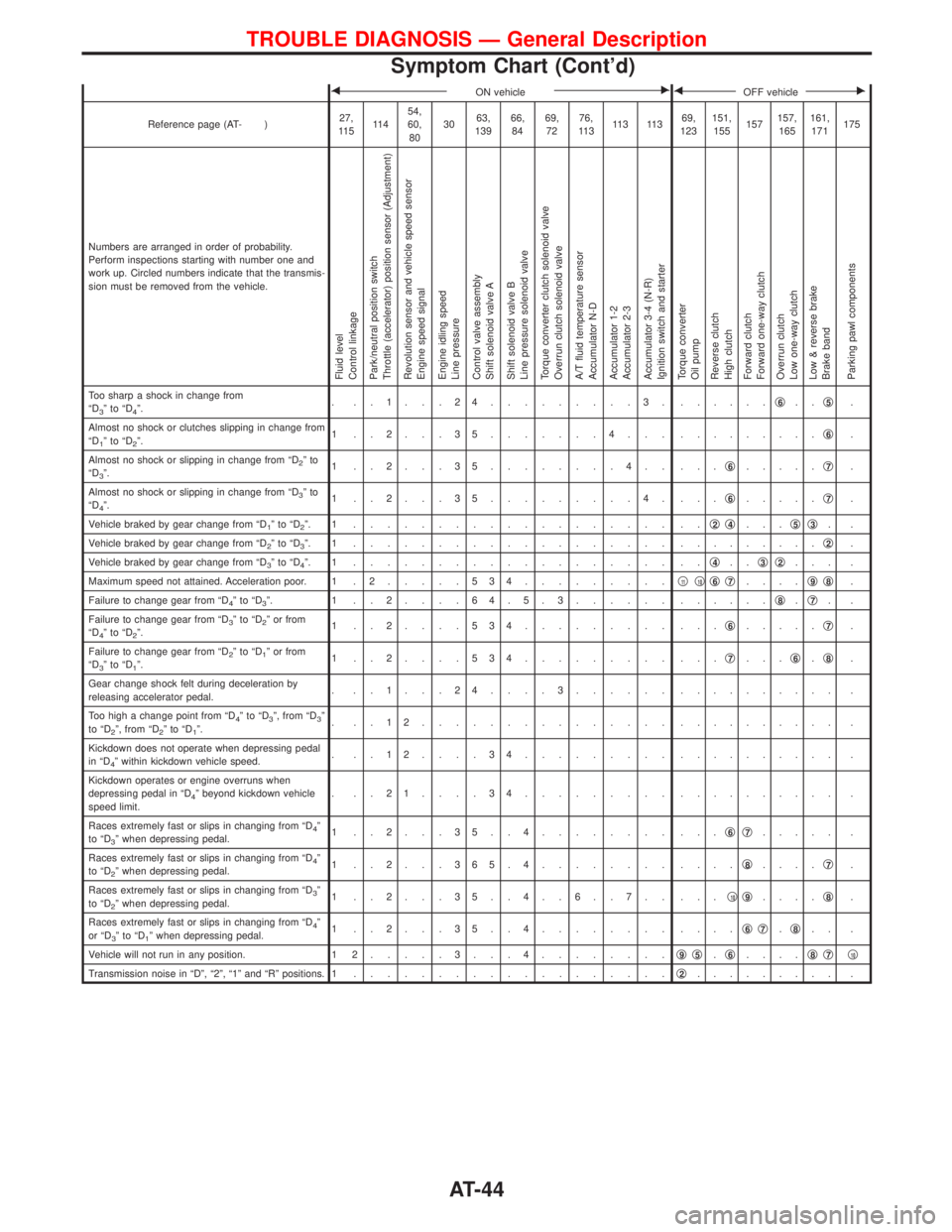
Numbers are arranged in order of probability.
Perform inspections starting with number one and
work up. Circled numbers indicate that the transmis-
sion must be removed from the vehicle.
Fluid level
Control linkage
Park/neutral position switch
Throttle (accelerator) position sensor (Adjustment)
Revolution sensor and vehicle speed sensor
Engine speed signal
Engine idling speed
Line pressure
Control valve assembly
Shift solenoid valve A
Shift solenoid valve B
Line pressure solenoid valve
Torque converter clutch solenoid valve
Overrun clutch solenoid valve
A/T fluid temperature sensor
Accumulator N-D
Accumulator 1-2
Accumulator 2-3
Accumulator 3-4 (N-R)
Ignition switch and starter
Torque converter
Oil pump
Reverse clutch
High clutch
Forward clutch
Forward one-way clutch
Overrun clutch
Low one-way clutch
Low & reverse brake
Brake band
Parking pawl components
Too sharp a shock in change from
ªD3ºtoªD4º.. ..1...24.........3. ......q6..q5.
Almost no shock or clutches slipping in change from
ªD
1ºtoªD2º.1 ..2...35.......4... .........q6.
Almost no shock or slipping in change from ªD
2ºto
ªD3º.1 ..2...35........4.. ...q6.....q7.
Almost no shock or slipping in change from ªD
3ºto
ªD4º.1 ..2...35.........4. ...q6.....q7.
Vehicle braked by gear change from ªD
1ºtoªD2º. 1 ................... ..q2q4...q5q3..
Vehicle braked by gear change from ªD
2ºtoªD3º. 1 ................... .........q2.
Vehicle braked by gear change from ªD
3ºtoªD4º. 1 ................... ..q4..q3q2... .
Maximum speed not attained. Acceleration poor. 1 . 2.....534.........q
11q10q6q7....q9q8.
Failure to change gear from ªD
4ºtoªD3º. 1 ..2....64.5.3...... ......q8.q7..
Failure to change gear from ªD
3ºtoªD2º or from
ªD4ºtoªD2º.1 ..2....534......... ...q6.....q7.
Failure to change gear from ªD
2ºtoªD1º or from
ªD3ºtoªD1º.1 ..2....534......... ...q7...q6.q8.
Gear change shock felt during deceleration by
releasing accelerator pedal.. ..1...24....3...... .......... .
Too high a change point from ªD
4ºtoªD3º, from ªD3º
to ªD2º, from ªD2ºtoªD1º.. ..12............... .......... .
Kickdown does not operate when depressing pedal
in ªD
4º within kickdown vehicle speed.. ..12....34......... .......... .
Kickdown operates or engine overruns when
depressing pedal in ªD
4º beyond kickdown vehicle
speed limit.. ..21....34......... .......... .
Races extremely fast or slips in changing from ªD
4º
to ªD3º when depressing pedal.1 ..2...35..4........ ...q6q7..... .
Races extremely fast or slips in changing from ªD
4º
to ªD2º when depressing pedal.1 ..2...365.4........ ....q8....q7.
Races extremely fast or slips in changing from ªD
3º
to ªD2º when depressing pedal.1 ..2...35..4..6..7.. ...q10q9....q8.
Races extremely fast or slips in changing from ªD
4º
or ªD3ºtoªD1º when depressing pedal.1 ..2...35..4........ ....q6q7.q8.. .
Vehicle will not run in any position. 1 2.....3...4........q
9q5.q6....q8q7q10
Transmission noise in ªDº, ª2º, ª1º and ªRº positions. 1...................q2......... .
TROUBLE DIAGNOSIS Ð General Description
Symptom Chart (Cont'd)
AT-44
Page 47 of 1767
FON vehicleEFOFF vehicleE
Reference page (AT- )27,
11 511 454,
60,
803063,
13966,
8469,
7276,
11 311 3 11 3139,
123151,
155157157,
165161,
171175
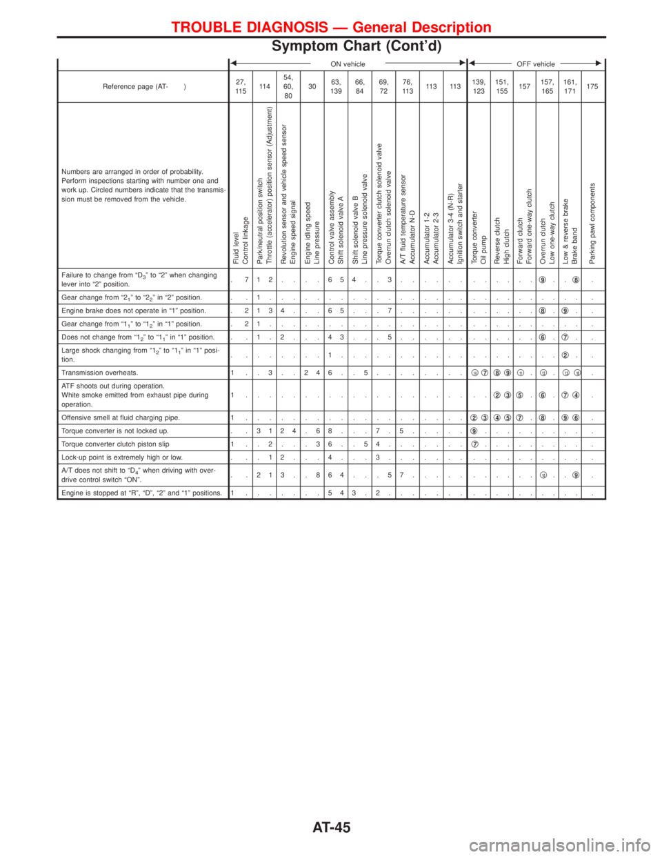
Numbers are arranged in order of probability.
Perform inspections starting with number one and
work up. Circled numbers indicate that the transmis-
sion must be removed from the vehicle.
Fluid level
Control linkage
Park/neutral position switch
Throttle (accelerator) position sensor (Adjustment)
Revolution sensor and vehicle speed sensor
Engine speed signal
Engine idling speed
Line pressure
Control valve assembly
Shift solenoid valve A
Shift solenoid valve B
Line pressure solenoid valve
Torque converter clutch solenoid valve
Overrun clutch solenoid valve
A/T fluid temperature sensor
Accumulator N-D
Accumulator 1-2
Accumulator 2-3
Accumulator 3-4 (N-R)
Ignition switch and starter
Torque converter
Oil pump
Reverse clutch
High clutch
Forward clutch
Forward one-way clutch
Overrun clutch
Low one-way clutch
Low & reverse brake
Brake band
Parking pawl components
Failure to change from ªD3º to ª2º when changing
lever into ª2º position.. 712....654..3...... ......q9..q8.
Gear change from ª2
1ºtoª22º in ª2º position. . . 1................. .......... .
Engine brake does not operate in ª1º position. .2134 . . . 65 . . . 7...... ......q
8.q9..
Gear change from ª1
1ºtoª12º in ª1º position. . 2 1................. .......... .
Does not change from ª1
2ºtoª11º in ª1º position. . . 1 . 2 . . . 4 3 . . . 5...... ......q6.q7..
Large shock changing from ª1
2ºtoª11º in ª1º posi-
tion.. .......1........... ........q2..
Transmission overheats. 1 . . 3 . . 2 4 6 . . 5........q
14q7q8q9q11.q12.q13q10.
ATF shoots out during operation.
White smoke emitted from exhaust pipe during
operation.1 ................... ..q
2q3q5.q6.q7q4.
Offensive smell at fluid charging pipe. 1...................q
2q3q4q5q7.q8.q9q6.
Torque converter is not locked up. . .3124 . 68 . . . 7 . 5.....q
9......... .
Torque converter clutch piston slip 1 . . 2 . . . 3 6 . . 5 4.......q
7......... .
Lock-up point is extremely high or low. . . . 1 2 . . . 4 . . . 3....... .......... .
A/T does not shift to ªD
4º when driving with over-
drive control switch ªONº.. .213..864...57..... ......q10..q9.
Engine is stopped at ªRº, ªDº, ª2º and ª1º positions. 1.......543.2....... .......... .
TROUBLE DIAGNOSIS Ð General Description
Symptom Chart (Cont'd)
AT-45
Page 941 of 1767
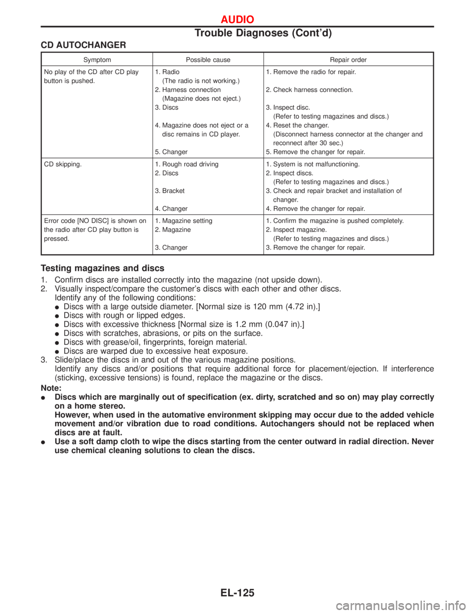
CD AUTOCHANGER
Symptom Possible cause Repair order
No play of the CD after CD play
button is pushed.1. Radio
(The radio is not working.)
2. Harness connection
(Magazine does not eject.)
3. Discs
4. Magazine does not eject or a
disc remains in CD player.
5. Changer1. Remove the radio for repair.
2. Check harness connection.
3. Inspect disc.
(Refer to testing magazines and discs.)
4. Reset the changer.
(Disconnect harness connector at the changer and
reconnect after 30 sec.)
5. Remove the changer for repair.
CD skipping. 1. Rough road driving
2. Discs
3. Bracket
4. Changer1. System is not malfunctioning.
2. Inspect discs.
(Refer to testing magazines and discs.)
3. Check and repair bracket and installation of
changer.
4. Remove the changer for repair.
Error code [NO DISC] is shown on
the radio after CD play button is
pressed.1. Magazine setting
2. Magazine
3. Changer1. Confirm the magazine is pushed completely.
2. Inspect magazine.
(Refer to testing magazines and discs.)
3. Remove the changer for repair.
Testing magazines and discs
1. Confirm discs are installed correctly into the magazine (not upside down).
2. Visually inspect/compare the customer's discs with each other and other discs.
Identify any of the following conditions:
IDiscs with a large outside diameter. [Normal size is 120 mm (4.72 in).]
IDiscs with rough or lipped edges.
IDiscs with excessive thickness [Normal size is 1.2 mm (0.047 in).]
IDiscs with scratches, abrasions, or pits on the surface.
IDiscs with grease/oil, fingerprints, foreign material.
IDiscs are warped due to excessive heat exposure.
3. Slide/place the discs in and out of the various magazine positions.
Identify any discs and/or positions that require additional force for placement/ejection. If interference
(sticking, excessive tensions) is found, replace the magazine or the discs.
Note:
IDiscs which are marginally out of specification (ex. dirty, scratched and so on) may play correctly
on a home stereo.
However, when used in the automative environment skipping may occur due to the added vehicle
movement and/or vibration due to road conditions. Autochangers should not be replaced when
discs are at fault.
IUse a soft damp cloth to wipe the discs starting from the center outward in radial direction. Never
use chemical cleaning solutions to clean the discs.
AUDIO
Trouble Diagnoses (Cont'd)
EL-125
Page 1221 of 1767
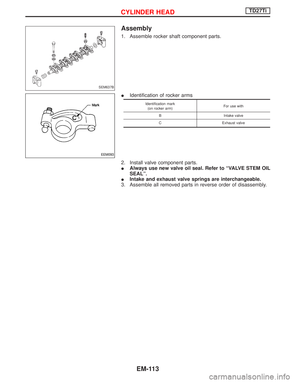
Assembly
1. Assemble rocker shaft component parts.
IIdentification of rocker arms
Identification mark
(on rocker arm)For use with
B Intake valve
C Exhaust valve
2. Install valve component parts.
IAlways use new valve oil seal. Refer to ªVALVE STEM OIL
SEALº.
IIntake and exhaust valve springs are interchangeable.
3. Assemble all removed parts in reverse order of disassembly.
SEM637B
EEM093
CYLINDER HEADTD27Ti
EM-113
Page 1320 of 1767
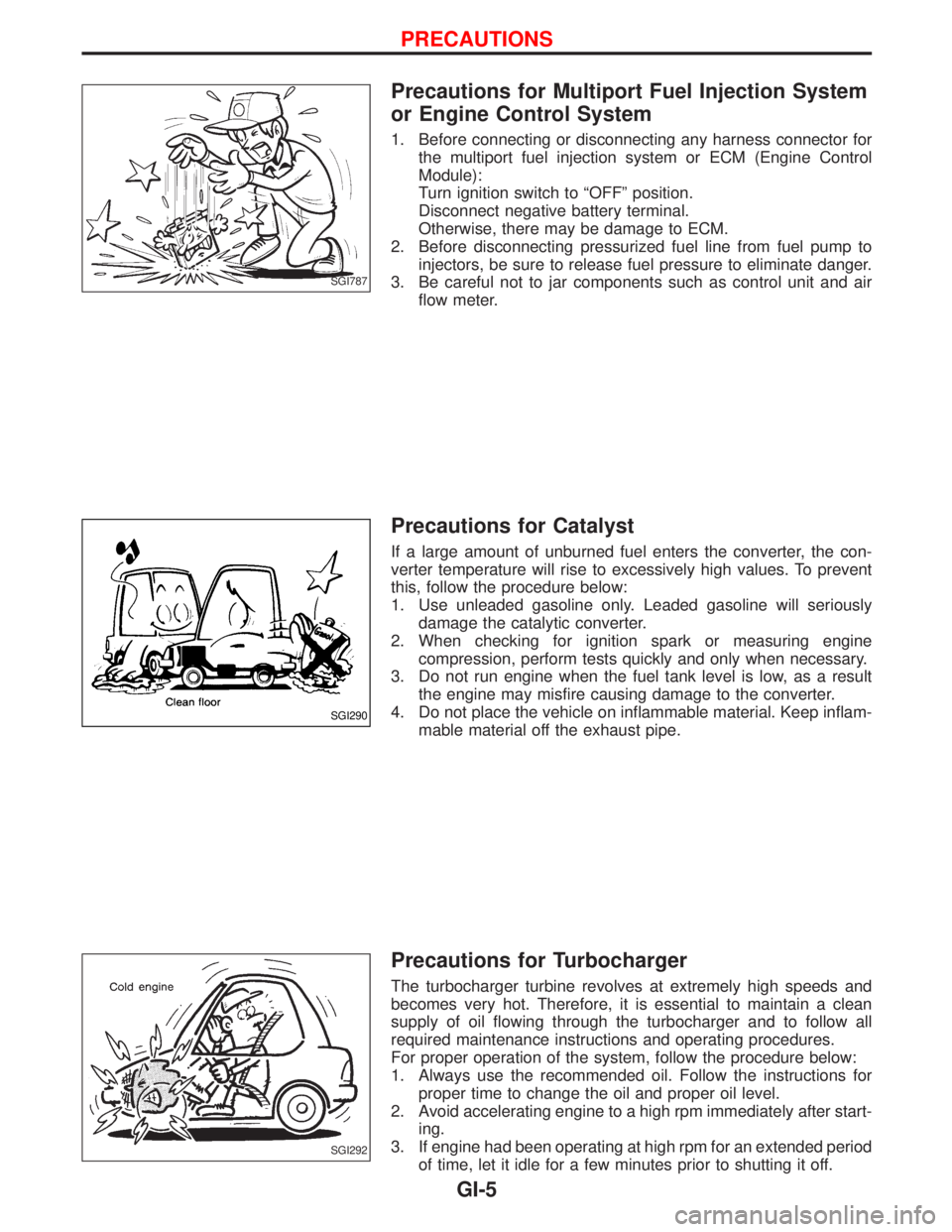
Precautions for Multiport Fuel Injection System
or Engine Control System
1. Before connecting or disconnecting any harness connector for
the multiport fuel injection system or ECM (Engine Control
Module):
Turn ignition switch to ªOFFº position.
Disconnect negative battery terminal.
Otherwise, there may be damage to ECM.
2. Before disconnecting pressurized fuel line from fuel pump to
injectors, be sure to release fuel pressure to eliminate danger.
3. Be careful not to jar components such as control unit and air
flow meter.
Precautions for Catalyst
If a large amount of unburned fuel enters the converter, the con-
verter temperature will rise to excessively high values. To prevent
this, follow the procedure below:
1. Use unleaded gasoline only. Leaded gasoline will seriously
damage the catalytic converter.
2. When checking for ignition spark or measuring engine
compression, perform tests quickly and only when necessary.
3. Do not run engine when the fuel tank level is low, as a result
the engine may misfire causing damage to the converter.
4. Do not place the vehicle on inflammable material. Keep inflam-
mable material off the exhaust pipe.
Precautions for Turbocharger
The turbocharger turbine revolves at extremely high speeds and
becomes very hot. Therefore, it is essential to maintain a clean
supply of oil flowing through the turbocharger and to follow all
required maintenance instructions and operating procedures.
For proper operation of the system, follow the procedure below:
1. Always use the recommended oil. Follow the instructions for
proper time to change the oil and proper oil level.
2. Avoid accelerating engine to a high rpm immediately after start-
ing.
3. If engine had been operating at high rpm for an extended period
of time, let it idle for a few minutes prior to shutting it off.
SGI787
SGI290
SGI292
PRECAUTIONS
GI-5
Page 1364 of 1767
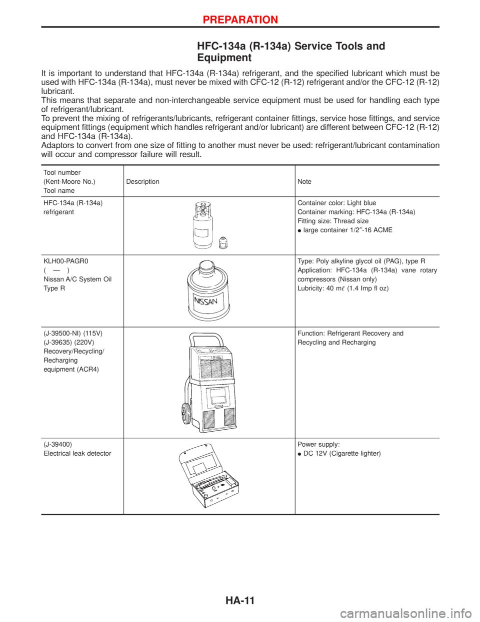
HFC-134a (R-134a) Service Tools and
Equipment
It is important to understand that HFC-134a (R-134a) refrigerant, and the specified lubricant which must be
used with HFC-134a (R-134a), must never be mixed with CFC-12 (R-12) refrigerant and/or the CFC-12 (R-12)
lubricant.
This means that separate and non-interchangeable service equipment must be used for handling each type
of refrigerant/lubricant.
To prevent the mixing of refrigerants/lubricants, refrigerant container fittings, service hose fittings, and service
equipment fittings (equipment which handles refrigerant and/or lubricant) are different between CFC-12 (R-12)
and HFC-134a (R-134a).
Adaptors to convert from one size of fitting to another must never be used: refrigerant/lubricant contamination
will occur and compressor failure will result.
Tool number
(Kent-Moore No.)
Tool nameDescription Note
HFC-134a (R-134a)
refrigerant
Container color: Light blue
Container marking: HFC-134a (R-134a)
Fitting size: Thread size
Ilarge container 1/2²-16 ACME
KLH00-PAGR0
(Ð)
Nissan A/C System Oil
Type R
Type: Poly alkyline glycol oil (PAG), type R
Application: HFC-134a (R-134a) vane rotary
compressors (Nissan only)
Lubricity: 40 m(1.4 Imp fl oz)
(J-39500-NI) (115V)
(J-39635) (220V)
Recovery/Recycling/
Recharging
equipment (ACR4)
Function: Refrigerant Recovery and
Recycling and Recharging
(J-39400)
Electrical leak detector
Power supply:
IDC 12V (Cigarette lighter)
PREPARATION
HA-11
Page 1375 of 1767
Lubrication Oil
Name: Nissan A/C System Oil Type R
Part number: KLH00-PAGR0
Maintenance of Oil Quantity in Compressor
The oil used to lubricate the compressor circulates through the
system with the refrigerant. Whenever any component of the sys-
tem is replaced or a large amount of gas leakage occurs, add oil
to the compressor to maintain the specified amount.
If oil quantity is not maintained properly, the following malfunctions
may result:
ILack of oil: May lead to a seized compressor
IExcessive oil: Inadequate cooling (thermal exchange impeded)
Checking and Adjusting
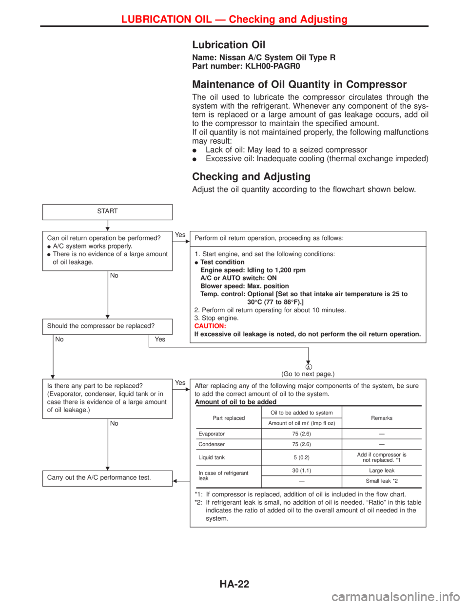
Adjust the oil quantity according to the flowchart shown below.
START
Can oil return operation be performed?
IA/C system works properly.
IThere is no evidence of a large amount
of oil leakage.
No
EYe s
Perform oil return operation, proceeding as follows:
-------------------------------------------------------------------------------------------------------------------------------------------------------------------------------------------------------------------------------------------------------------------------------------------------------------------------------------------------------------------------------------------------------------------------------------------------------------------------------------------------------------------------------------------------------------
1. Start engine, and set the following conditions:
ITest condition
Engine speed: Idling to 1,200 rpm
A/C or AUTO switch: ON
Blower speed: Max. position
Temp. control: Optional [Set so that intake air temperature is 25 to
30ÉC (77 to 86ÉF).]
2. Perform oil return operating for about 10 minutes.
3. Stop engine.
CAUTION:
If excessive oil leakage is noted, do not perform the oil return operation.
Should the compressor be replaced?
No Yes
qA(Go to next page.)
Is there any part to be replaced?
(Evaporator, condenser, liquid tank or in
case there is evidence of a large amount
of oil leakage.)
No
EYe s
After replacing any of the following major components of the system, be sure
to add the correct amount of oil to the system.
Amount of oil to be added
*1: If compressor is replaced, addition of oil is included in the flow chart.
*2: If refrigerant leak is small, no addition of oil is needed. ªRatioº in this table
indicates the ratio of added oil to the overall amount of oil needed in the
system.
Carry out the A/C performance test.F
Part replacedOil to be added to system
Remarks
Amount of oil m(Imp fl oz)
Evaporator 75 (2.6) Ð
Condenser 75 (2.6) Ð
Liquid tank 5 (0.2)Add if compressor is
not replaced. *1
In case of refrigerant
leak30 (1.1) Large leak
Ð Small leak *2
H
H
H
H
H
LUBRICATION OIL Ð Checking and Adjusting
HA-22