2002 NISSAN TERRANO warning light
[x] Cancel search: warning lightPage 95 of 1767
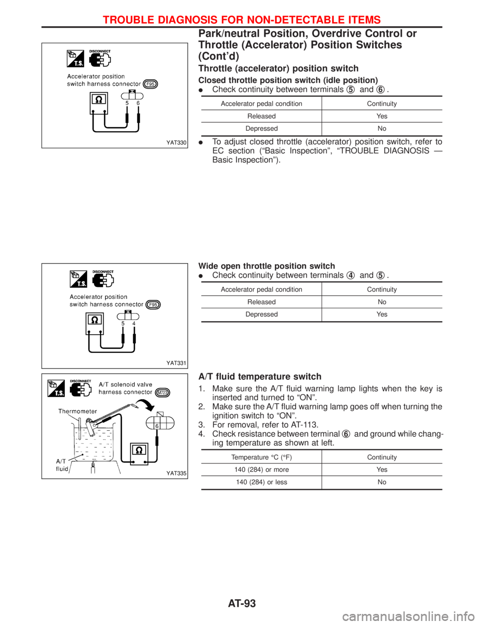
Throttle (accelerator) position switch
Closed throttle position switch (idle position)
ICheck continuity between terminalsq
5andq6.
Accelerator pedal condition Continuity
Released Yes
Depressed No
ITo adjust closed throttle (accelerator) position switch, refer to
EC section (ªBasic Inspectionº, ªTROUBLE DIAGNOSIS Ð
Basic Inspectionº).
Wide open throttle position switch
ICheck continuity between terminalsq
4andq5.
Accelerator pedal condition Continuity
Released No
Depressed Yes
A/T fluid temperature switch
1. Make sure the A/T fluid warning lamp lights when the key is
inserted and turned to ªONº.
2. Make sure the A/T fluid warning lamp goes off when turning the
ignition switch to ªONº.
3. For removal, refer to AT-113.
4. Check resistance between terminalq
6and ground while chang-
ing temperature as shown at left.
Temperature ÉC (ÉF) Continuity
140 (284) or more Yes
140 (284) or less No
YAT330
YAT331
YAT335
TROUBLE DIAGNOSIS FOR NON-DETECTABLE ITEMS
Park/neutral Position, Overdrive Control or
Throttle (Accelerator) Position Switches
(Cont'd)
AT-93
Page 239 of 1767
Purpose
The Anti-lock Brake System (ABS) with an integrated Electronic Brake force Distribution (EBD) system con-
sists of electronic and hydraulic components. It allows you to control the braking force so that wheel lock can
be avoided during braking.
The advantages of ABS with EBD
1) Better tracking performance through improved steering wheel control.
2) Improved maneuverability and safer vehicle control.
3) Improved vehicle stability by preventing flat spins.
4) Shorter stopping distance and optimal utilisation of the rear brakes under many different circumstances.
Operation
IABS with EBD has self-test capabilities. The ABS warning lamp is illuminated for 1 second each time the
ignition switch is turned ªONº. After the engine is started, the ABS warning lamp turns off. An ABS self-test
is performed the first time the vehicle reaches 6 km/h (4 MPH) to ensure the system is operational. A
mechanical noise may be heard as the ABS performs this self-test and is a normal part of the self-test
feature. If a malfunction is detected during this check, the ABS warning lamp will stay on.
During the self-test, it also performs a EBD check when it detects a failure the ABS warning light will go
on simultaneously with the brake warning light and an audible sound will sound constantly.
IEBD system will only operate when the ABS is not in active status and it uses the inlet valves of ABS con-
trol unit to limit the pressure to the rear wheels when they tend to go into slip.
IWhen the vehicle speed is less than 10 km/h (6 MPH) the ABS system does not operate.
IWhile driving, a mechanical noise may be heard during ABS operation, this is a normal system condition.
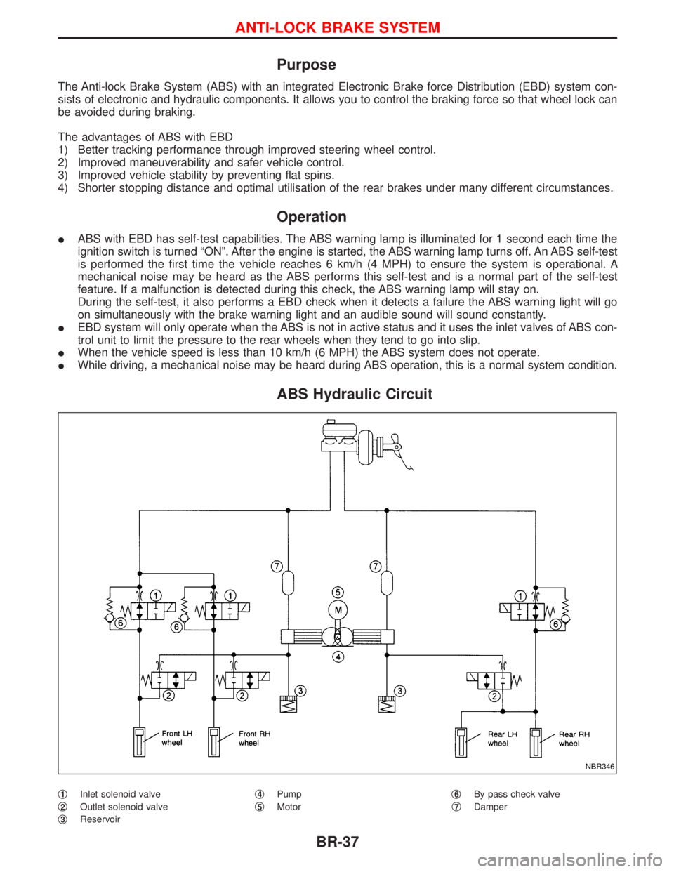
ABS Hydraulic Circuit
q1Inlet solenoid valve
q
2Outlet solenoid valve
q
3Reservoirq
4Pump
q
5Motorq
6By pass check valve
q
7Damper
NBR346
ANTI-LOCK BRAKE SYSTEM
BR-37
Page 240 of 1767
System Description
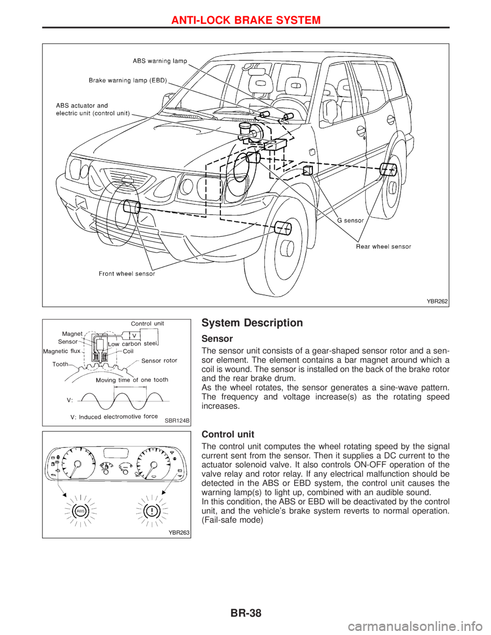
Sensor
The sensor unit consists of a gear-shaped sensor rotor and a sen-
sor element. The element contains a bar magnet around which a
coil is wound. The sensor is installed on the back of the brake rotor
and the rear brake drum.
As the wheel rotates, the sensor generates a sine-wave pattern.
The frequency and voltage increase(s) as the rotating speed
increases.
Control unit
The control unit computes the wheel rotating speed by the signal
current sent from the sensor. Then it supplies a DC current to the
actuator solenoid valve. It also controls ON-OFF operation of the
valve relay and rotor relay. If any electrical malfunction should be
detected in the ABS or EBD system, the control unit causes the
warning lamp(s) to light up, combined with an audible sound.
In this condition, the ABS or EBD will be deactivated by the control
unit, and the vehicle's brake system reverts to normal operation.
(Fail-safe mode)
YBR262
SBR124B
YBR263
ANTI-LOCK BRAKE SYSTEM
BR-38
Page 396 of 1767
IIf the battery is disconnected, the emission-related diagnostic information will be lost after approx.
24 hours.
IErasing the emission-related diagnostic information using CONSULT-II is easier and quicker than
switching the diagnostic test mode using the data link connector.
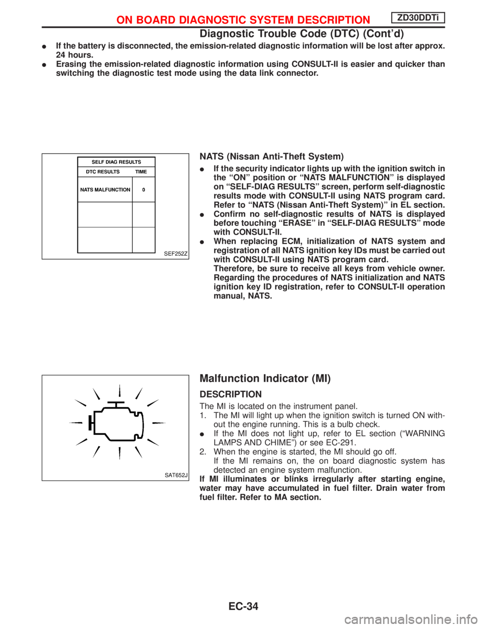
NATS (Nissan Anti-Theft System)
IIf the security indicator lights up with the ignition switch in
the ªONº position or ªNATS MALFUNCTIONº is displayed
on ªSELF-DIAG RESULTSº screen, perform self-diagnostic
results mode with CONSULT-II using NATS program card.
Refer to ªNATS (Nissan Anti-Theft System)º in EL section.
IConfirm no self-diagnostic results of NATS is displayed
before touching ªERASEº in ªSELF-DIAG RESULTSº mode
with CONSULT-II.
IWhen replacing ECM, initialization of NATS system and
registration of all NATS ignition key IDs must be carried out
with CONSULT-II using NATS program card.
Therefore, be sure to receive all keys from vehicle owner.
Regarding the procedures of NATS initialization and NATS
ignition key ID registration, refer to CONSULT-II operation
manual, NATS.
Malfunction Indicator (MI)
DESCRIPTION
The MI is located on the instrument panel.
1. The MI will light up when the ignition switch is turned ON with-
out the engine running. This is a bulb check.
IIf the MI does not light up, refer to EL section (ªWARNING
LAMPS AND CHIMEº) or see EC-291.
2. When the engine is started, the MI should go off.
If the MI remains on, the on board diagnostic system has
detected an engine system malfunction.
If MI illuminates or blinks irregularly after starting engine,
water may have accumulated in fuel filter. Drain water from
fuel filter. Refer to MA section.
SEF252Z
SAT652J
ON BOARD DIAGNOSTIC SYSTEM DESCRIPTIONZD30DDTi
Diagnostic Trouble Code (DTC) (Cont'd)
EC-34
Page 397 of 1767
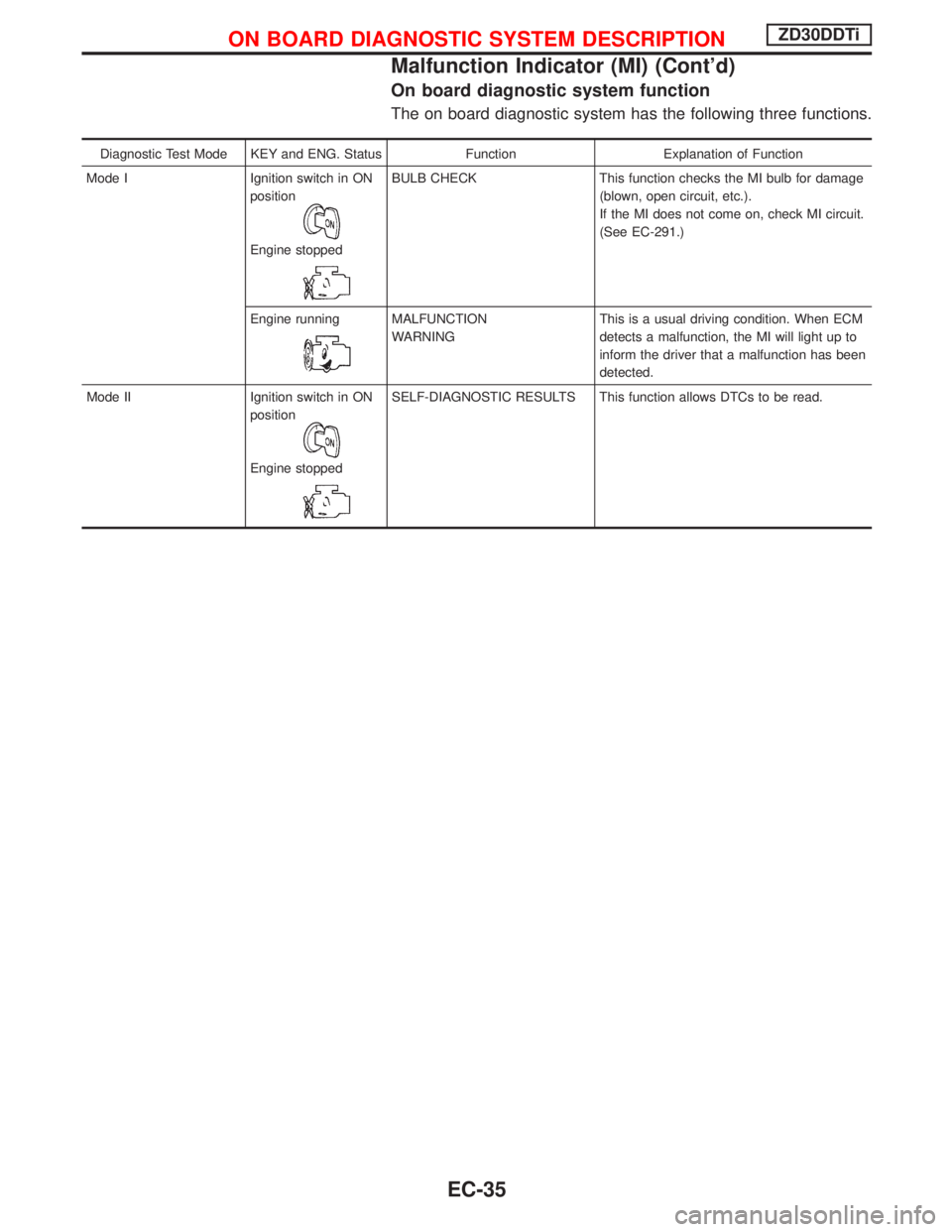
On board diagnostic system function
The on board diagnostic system has the following three functions.
Diagnostic Test Mode KEY and ENG. Status Function Explanation of Function
Mode I Ignition switch in ON
position
Engine stopped
BULB CHECK This function checks the MI bulb for damage
(blown, open circuit, etc.).
If the MI does not come on, check MI circuit.
(See EC-291.)
Engine running
MALFUNCTION
WARNINGThis is a usual driving condition. When ECM
detects a malfunction, the MI will light up to
inform the driver that a malfunction has been
detected.
Mode II Ignition switch in ON
position
Engine stopped
SELF-DIAGNOSTIC RESULTS This function allows DTCs to be read.
ON BOARD DIAGNOSTIC SYSTEM DESCRIPTIONZD30DDTi
Malfunction Indicator (MI) (Cont'd)
EC-35
Page 684 of 1767
How to Erase DTC (Without CONSULT-II)
1. If the ignition switch stays ªONº after repair work, be sure to turn ignition switch ªOFFº once. Wait at least
5 seconds and then turn it ªONº (engine stopped) again.
2. Change the diagnostic test mode from Mode II to Mode I by using the data link connector. (See EC-323.)
The emission related diagnostic information in the ECM can be erased by changing the diagnostic test mode.
IIf the battery is disconnected, the emission-related diagnostic information will be lost after approx.
24 hours.
IErasing the emission-related diagnostic information using CONSULT-II is easier and quicker than
switching the diagnostic test mode using the data link connector.
Malfunction Indicator (MI)
1. The malfunction indicator will light up when the ignition switch
is turned ON without the engine running. This is a bulb check.
IIf the malfunction indicator does not light up, refer to EL sec-
tion (ªWARNING LAMPS/WIRING DIAGRAMº) or see MI &
DATA LINK CONNECTORS.
2. When the engine is started, the malfunction indicator should go
off.
If the lamp remains on, the on board diagnostic system has
detected an engine system malfunction.
If MI illuminates or flashes irregularly after starting engine,
water may have accumulated in fuel filter. Drain water from
fuel filter.
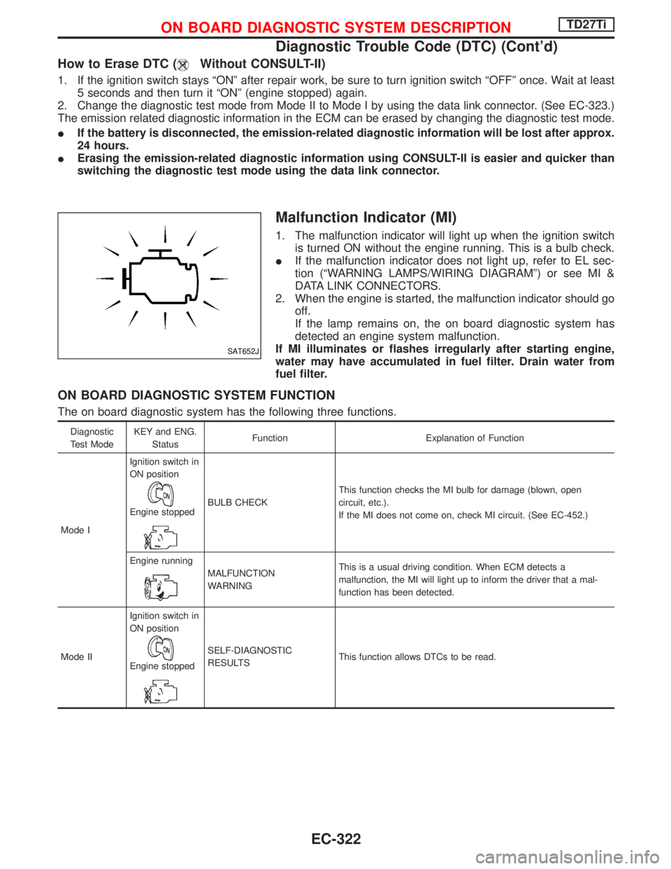
ON BOARD DIAGNOSTIC SYSTEM FUNCTION
The on board diagnostic system has the following three functions.
Diagnostic
Test ModeKEY and ENG.
StatusFunction Explanation of Function
Mode IIgnition switch in
ON position
Engine stoppedBULB CHECKThis function checks the MI bulb for damage (blown, open
circuit, etc.).
If the MI does not come on, check MI circuit. (See EC-452.)
Engine running
MALFUNCTION
WARNINGThis is a usual driving condition. When ECM detects a
malfunction, the MI will light up to inform the driver that a mal-
function has been detected.
Mode IIIgnition switch in
ON position
Engine stopped
SELF-DIAGNOSTIC
RESULTSThis function allows DTCs to be read.
SAT652J
ON BOARD DIAGNOSTIC SYSTEM DESCRIPTIONTD27Ti
Diagnostic Trouble Code (DTC) (Cont'd)
EC-322
Page 817 of 1767

ELECTRICAL SYSTEM
SECTION
EL
When you read wiring diagrams:
IRead GI section, ªHOW TO READ WIRING DIAGRAMSº.
CONTENTS
HARNESS CONNECTOR................................................3
Description ...................................................................3
STANDARDIZED RELAYS..............................................4
Description ...................................................................4
POWER SUPPLY ROUTING...........................................6
Schematic ....................................................................6
Wiring Diagram - POWER - ........................................8
Fuse ...........................................................................17
Fusible Link................................................................17
Circuit Breaker Inspection .........................................17
GROUND DISTRIBUTION.............................................18
COMBINATION SWITCH...............................................23
Check .........................................................................23
Replacement ..............................................................24
STEERING SWITCH......................................................25
Check .........................................................................25
HEADLAMP - Without Daytime Light System -.........26
Wiring Diagram - H/LAMP -.......................................26
HEADLAMP - Daytime Light System -.......................29
Operation ...................................................................29
Schematic ..................................................................30
Wiring Diagram - DTRL - ...........................................31
HEADLAMP - Headlamp Aiming Control -.................37
Description .................................................................37
Replacing Headlamp Aiming Actuator .......................38
Wiring Diagram - H/AIM - ..........................................39
Trouble Diagnoses.....................................................42
HEADLAMP...................................................................43
Bulb Replacement .....................................................43
Aiming Adjustment .....................................................43
EXTERIOR LAMP..........................................................45
Wiring Diagram - TAIL/L - ..........................................45
Wiring Diagram - STOP/L - .......................................48
Wiring Diagram - BACK/L - .......................................49
Wiring Diagram - F/FOG - .........................................51
Front Fog Lamp Aiming Adjustment ..........................53
Wiring Diagram - R/FOG -.........................................54
Schematic ..................................................................55Wiring Diagram - TURN - ..........................................56
Bulb Specifications ....................................................60
INTERIOR LAMP...........................................................61
Schematic ..................................................................61
Wiring Diagram - ILL - ...............................................62
Wiring Diagram - INT/L - ...........................................66
METER AND GAUGES.................................................70
Combination Meter ....................................................70
Schematic ..................................................................71
Wiring Diagram - METER - .......................................72
Combination Meter Self-Diagnosis ............................76
Components Inspection .............................................78
Trouble Diagnoses.....................................................79
Fuel Tank Gauge Unit Check ....................................80
Thermal Transmitter Check .......................................80
Oil Pressure Switch Check ........................................80
WARNING LAMPS AND CHIME...................................81
Schematic ..................................................................81
Wiring Diagram - WARN - .........................................82
Diode Check ..............................................................92
Wiring Diagram - CHIME - ........................................93
WIPER AND WASHER..................................................94
Wiring Diagram - WIPER - ........................................94
Wiring Diagram - WIP/R -..........................................96
Installation ..................................................................98
Washer Nozzle Adjustment .......................................99
Check Valve ...............................................................99
Wiring Diagram - HLC - ...........................................100
HORN, CIGARETTE LIGHTER AND CLOCK............104
Wiring Diagram - HORN - .......................................104
Wiring Diagram - CIGAR -.......................................105
Wiring Diagram - CLOCK -......................................106
REAR WINDOW DEFOGGER AND DOOR
MIRROR DEFOGGER.................................................107
Wiring Diagram - DEF - ...........................................107
Filament Check ........................................................109
Filament Repair ....................................................... 110
AUDIO.......................................................................... 111
Page 996 of 1767
System Description
The TCU (Time Control Unit) has the following functions.
INTERIOR LAMP TIMER
The interior lamp timer is controlled by the TCU.
The TCU keeps the interior lamp illuminated for about 30 seconds when:
Ithe ignition key is turned from ªONº to ªACCº to ªLOCKº
Ithe driver's door is unlocked
Ia door is opened and then closed while the ignition switch is in the ªOFFº position. (Interior lamp switch
in the ªDOORº position).
The timer is canceled when:
Idriver's door is locked, or
Iignition switch is turned ªONº.
IGNITION KEY WARNING CHIME AND LIGHT WARNING CHIME
The ignition key and light warning chime are controlled by the TCU.
The warning chime is combined with the TCU.
The light warning chime will not sound, when ignition switch is in the ªONº or ªSTARTº position. (When power
supply exists at TCU terminal
U01.)
With ignition switch in the OFF position, driver's door open, and lighting switch in 1ST or 2ND position, warn-
ing chime will sound.
Or, with the key in the ignition switch in the ªACCº or ªOFFº position, and locking the driver's door from the
inside, the warning buzzer will sound.
REAR WINDOW DEFOGGER TIMER
The rear window defogger and door mirror defogger system are controlled by the TCU.
The rear window and door mirror defogger operate only for approximately 15 minutes.
POWER DOOR LOCK (Super Lock)
The power door lock (super lock) is controlled by the TCU.
For further information, refer to ªPOWER DOOR LOCK Ð Super Lockº (EL-145).
MULTI-REMOTE CONTROL SYSTEM
The multi-remote control system is controlled by the TCU.
When the following input signals are both supplied:
IKey switch OFF (when ignition key is not inserted in key cylinder);
Idoor switch CLOSED (when all the doors are closed);
The two above signals are already input into time control unit. At this point, time control unit receives a LOCK
signal from remote controller. Time control unit locks all doors and set super lock with input of LOCK signal
from remote controller.
When an UNLOCK signal is sent from remote controller once, driver's door will be unlocked and release super
lock.
Then, if an UNLOCK signal is sent from remote controller again, all other door will be unlocked.
MULTI-REMOTE CONTROLLER ID CODE ENTRY
For detailed procedure, refer to ªID Code Entry Procedureº (EL-179).
THEFT WARNING SYSTEM
The theft warning system is controlled by the TCU.
For further information, refer to ªTHEFT WARNING SYSTEMº (EL-209).
TIME CONTROL UNIT (TCU)
EL-180