2002 NISSAN TERRANO oil change
[x] Cancel search: oil changePage 1386 of 1767
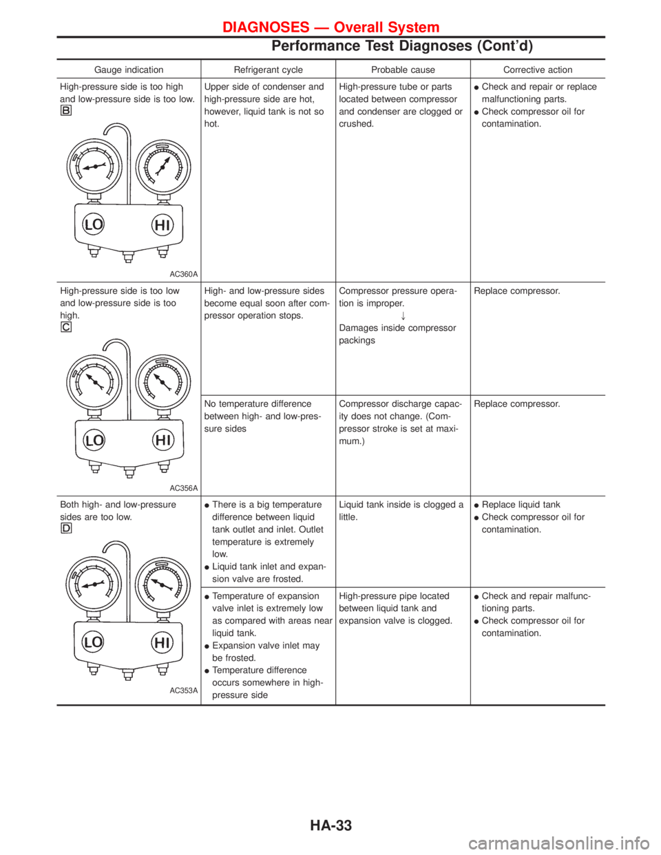
Gauge indication Refrigerant cycle Probable cause Corrective action
High-pressure side is too high
and low-pressure side is too low.
AC360A
Upper side of condenser and
high-pressure side are hot,
however, liquid tank is not so
hot.High-pressure tube or parts
located between compressor
and condenser are clogged or
crushed.ICheck and repair or replace
malfunctioning parts.
ICheck compressor oil for
contamination.
High-pressure side is too low
and low-pressure side is too
high.
AC356A
High- and low-pressure sides
become equal soon after com-
pressor operation stops.Compressor pressure opera-
tion is improper.
"
Damages inside compressor
packingsReplace compressor.
No temperature difference
between high- and low-pres-
sure sidesCompressor discharge capac-
ity does not change. (Com-
pressor stroke is set at maxi-
mum.)Replace compressor.
Both high- and low-pressure
sides are too low.
AC353A
IThere is a big temperature
difference between liquid
tank outlet and inlet. Outlet
temperature is extremely
low.
ILiquid tank inlet and expan-
sion valve are frosted.Liquid tank inside is clogged a
little.IReplace liquid tank
ICheck compressor oil for
contamination.
ITemperature of expansion
valve inlet is extremely low
as compared with areas near
liquid tank.
IExpansion valve inlet may
be frosted.
ITemperature difference
occurs somewhere in high-
pressure sideHigh-pressure pipe located
between liquid tank and
expansion valve is clogged.ICheck and repair malfunc-
tioning parts.
ICheck compressor oil for
contamination.
DIAGNOSES Ð Overall System
Performance Test Diagnoses (Cont'd)
HA-33
Page 1387 of 1767
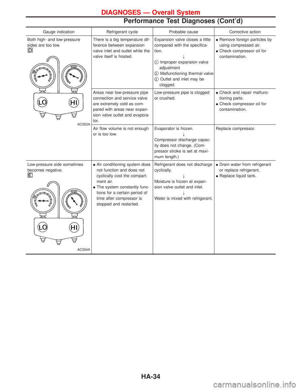
Gauge indication Refrigerant cycle Probable cause Corrective action
Both high- and low-pressure
sides are too low.
AC353A
There is a big temperature dif-
ference between expansion
valve inlet and outlet while the
valve itself is frosted.Expansion valve closes a little
compared with the specifica-
tion.
"
q
1Improper expansion valve
adjustment
q
2Malfunctioning thermal valve
q
3Outlet and inlet may be
clogged.IRemove foreign particles by
using compressed air.
ICheck compressor oil for
contamination.
Areas near low-pressure pipe
connection and service valve
are extremely cold as com-
pared with areas near expan-
sion valve outlet and evapora-
tor.Low-pressure pipe is clogged
or crushed.ICheck and repair malfunc-
tioning parts.
ICheck compressor oil for
contamination.
Air flow volume is not enough
or is too low.Evaporator is frozen.
"
Compressor discharge capac-
ity does not change. (Com-
pressor stroke is set at maxi-
mum length.)Replace compressor.
Low-pressure side sometimes
becomes negative.
AC354A
IAir conditioning system does
not function and does not
cyclically cool the compart-
ment air.
IThe system constantly func-
tions for a certain period of
time after compressor is
stopped and restarted.Refrigerant does not discharge
cyclically.
"
Moisture is frozen at expan-
sion valve outlet and inlet.
"
Water is mixed with refrigerant.IDrain water from refrigerant
or replace refrigerant.
IReplace liquid tank.
DIAGNOSES Ð Overall System
Performance Test Diagnoses (Cont'd)
HA-34
Page 1422 of 1767
INT/V - Wiring diagram ................................EC-274
Intake air control valve control solenoid
valve .........................................................EC-273
Intake Air Volume .........................................EC-143
Intake door control linkage adjustment ..........HA-63
Intake manifold...............................................EM-12
Interior .............................................................BT-18
Interior lamp ..............................................EL-61, 66
ISO 15031-2 Terminology................................GI-35
K
Knuckle spindle ...............................................FA-20
L
License lamp ...................................................EL-45
Limited slip diff. adjustment............................PD-45
Limited slip diff. assembly ..............................PD-47
Limited slip diff. disassembly ...................PD-43, 44
Limited slip diff. inspection .............................PD-44
Line pressure solenoid valve ..........................AT-84
Line pressure test (A/T) ..........................AT-30, 196
Liquid gasket application .................................EM-3
Location of electrical units ............EL-241, 242, 244
Lock, door ...........................................BT-10, 12, 14
Low and reverse brake .................................AT-161
LSV (Load sensing valve) ..............................BR-10
Lubricants.......................................................MA-17
Lubrication circuit (engine) .........................LC-3, 20
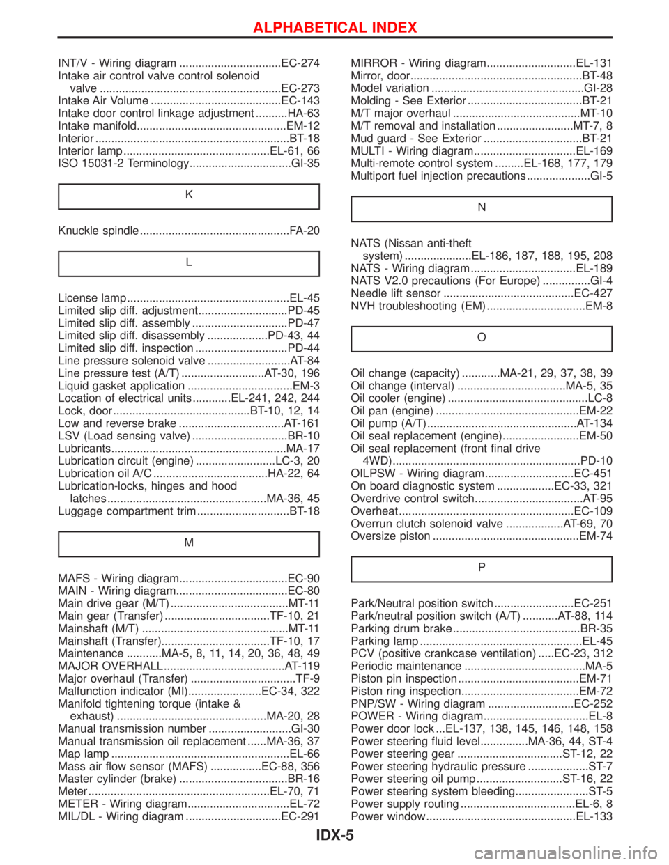
Lubrication oil A/C ....................................HA-22, 64
Lubrication-locks, hinges and hood
latches ..................................................MA-36, 45
Luggage compartment trim .............................BT-18
M
MAFS - Wiring diagram..................................EC-90
MAIN - Wiring diagram...................................EC-80
Main drive gear (M/T) .....................................MT-11
Main gear (Transfer) .................................TF-10, 21
Mainshaft (M/T) ..............................................MT-11
Mainshaft (Transfer)..................................TF-10, 17
Maintenance ...........MA-5, 8, 11, 14, 20, 36, 48, 49
MAJOR OVERHALL ......................................AT-119
Major overhaul (Transfer) .................................TF-9
Malfunction indicator (MI).......................EC-34, 322
Manifold tightening torque (intake &
exhaust) ...............................................MA-20, 28
Manual transmission number ..........................GI-30
Manual transmission oil replacement ......MA-36, 37
Map lamp ........................................................EL-66
Mass air flow sensor (MAFS) ................EC-88, 356
Master cylinder (brake) ..................................BR-16
Meter .........................................................EL-70, 71
METER - Wiring diagram................................EL-72
MIL/DL - Wiring diagram ..............................EC-291MIRROR - Wiring diagram............................EL-131
Mirror, door......................................................BT-48
Model variation ................................................GI-28
Molding - See Exterior ....................................BT-21
M/T major overhaul ........................................MT-10
M/T removal and installation ........................MT-7, 8
Mud guard - See Exterior ...............................BT-21
MULTI - Wiring diagram................................EL-169
Multi-remote control system .........EL-168, 177, 179
Multiport fuel injection precautions ....................GI-5
N
NATS (Nissan anti-theft
system) .....................EL-186, 187, 188, 195, 208
NATS - Wiring diagram .................................EL-189
NATS V2.0 precautions (For Europe) ...............GI-4
Needle lift sensor .........................................EC-427
NVH troubleshooting (EM) ...............................EM-8
O
Oil change (capacity) ............MA-21, 29, 37, 38, 39
Oil change (interval) ..................................MA-5, 35
Oil cooler (engine) ............................................LC-8
Oil pan (engine) .............................................EM-22
Oil pump (A/T)...............................................AT-134
Oil seal replacement (engine)........................EM-50
Oil seal replacement (front final drive
4WD)...........................................................PD-10
OILPSW - Wiring diagram............................EC-451
On board diagnostic system ..................EC-33, 321
Overdrive control switch..................................AT-95
Overheat .......................................................EC-109
Overrun clutch solenoid valve ..................AT-69, 70
Oversize piston ..............................................EM-74
P
Park/Neutral position switch .........................EC-251
Park/neutral position switch (A/T) ...........AT-88, 114
Parking drum brake ........................................BR-35
Parking lamp ...................................................EL-45
PCV (positive crankcase ventilation) .....EC-23, 312
Periodic maintenance ......................................MA-5
Piston pin inspection ......................................EM-71
Piston ring inspection.....................................EM-72
PNP/SW - Wiring diagram ...........................EC-252
POWER - Wiring diagram.................................EL-8
Power door lock ...EL-137, 138, 145, 146, 148, 158
Power steering fluid level...............MA-36, 44, ST-4
Power steering gear .................................ST-12, 22
Power steering hydraulic pressure ...................ST-7
Power steering oil pump ...........................ST-16, 22
Power steering system bleeding.......................ST-5
Power supply routing ....................................EL-6, 8
Power window ...............................................EL-133
ALPHABETICAL INDEX
IDX-5
Page 1463 of 1767
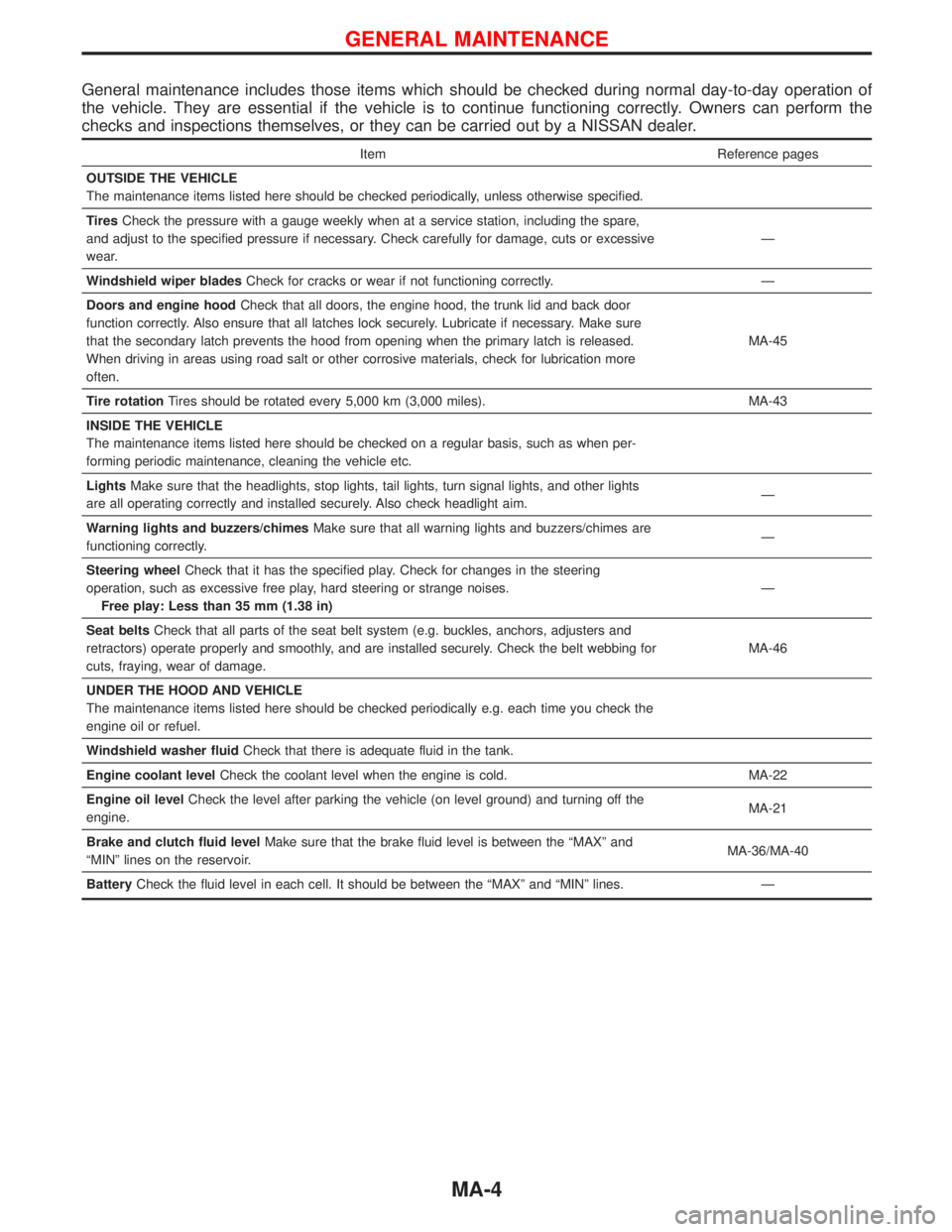
General maintenance includes those items which should be checked during normal day-to-day operation of
the vehicle. They are essential if the vehicle is to continue functioning correctly. Owners can perform the
checks and inspections themselves, or they can be carried out by a NISSAN dealer.
Item Reference pages
OUTSIDE THE VEHICLE
The maintenance items listed here should be checked periodically, unless otherwise specified.
TiresCheck the pressure with a gauge weekly when at a service station, including the spare,
and adjust to the specified pressure if necessary. Check carefully for damage, cuts or excessive
wear.Ð
Windshield wiper bladesCheck for cracks or wear if not functioning correctly. Ð
Doors and engine hoodCheck that all doors, the engine hood, the trunk lid and back door
function correctly. Also ensure that all latches lock securely. Lubricate if necessary. Make sure
that the secondary latch prevents the hood from opening when the primary latch is released.
When driving in areas using road salt or other corrosive materials, check for lubrication more
often.MA-45
Tire rotationTires should be rotated every 5,000 km (3,000 miles). MA-43
INSIDE THE VEHICLE
The maintenance items listed here should be checked on a regular basis, such as when per-
forming periodic maintenance, cleaning the vehicle etc.
LightsMake sure that the headlights, stop lights, tail lights, turn signal lights, and other lights
are all operating correctly and installed securely. Also check headlight aim.Ð
Warning lights and buzzers/chimesMake sure that all warning lights and buzzers/chimes are
functioning correctly.Ð
Steering wheelCheck that it has the specified play. Check for changes in the steering
operation, such as excessive free play, hard steering or strange noises.
Free play: Less than 35 mm (1.38 in)Ð
Seat beltsCheck that all parts of the seat belt system (e.g. buckles, anchors, adjusters and
retractors) operate properly and smoothly, and are installed securely. Check the belt webbing for
cuts, fraying, wear of damage.MA-46
UNDER THE HOOD AND VEHICLE
The maintenance items listed here should be checked periodically e.g. each time you check the
engine oil or refuel.
Windshield washer fluidCheck that there is adequate fluid in the tank.
Engine coolant levelCheck the coolant level when the engine is cold. MA-22
Engine oil levelCheck the level after parking the vehicle (on level ground) and turning off the
engine.MA-21
Brake and clutch fluid levelMake sure that the brake fluid level is between the ªMAXº and
ªMINº lines on the reservoir.MA-36/MA-40
BatteryCheck the fluid level in each cell. It should be between the ªMAXº and ªMINº lines. Ð
GENERAL MAINTENANCE
MA-4
Page 1480 of 1767
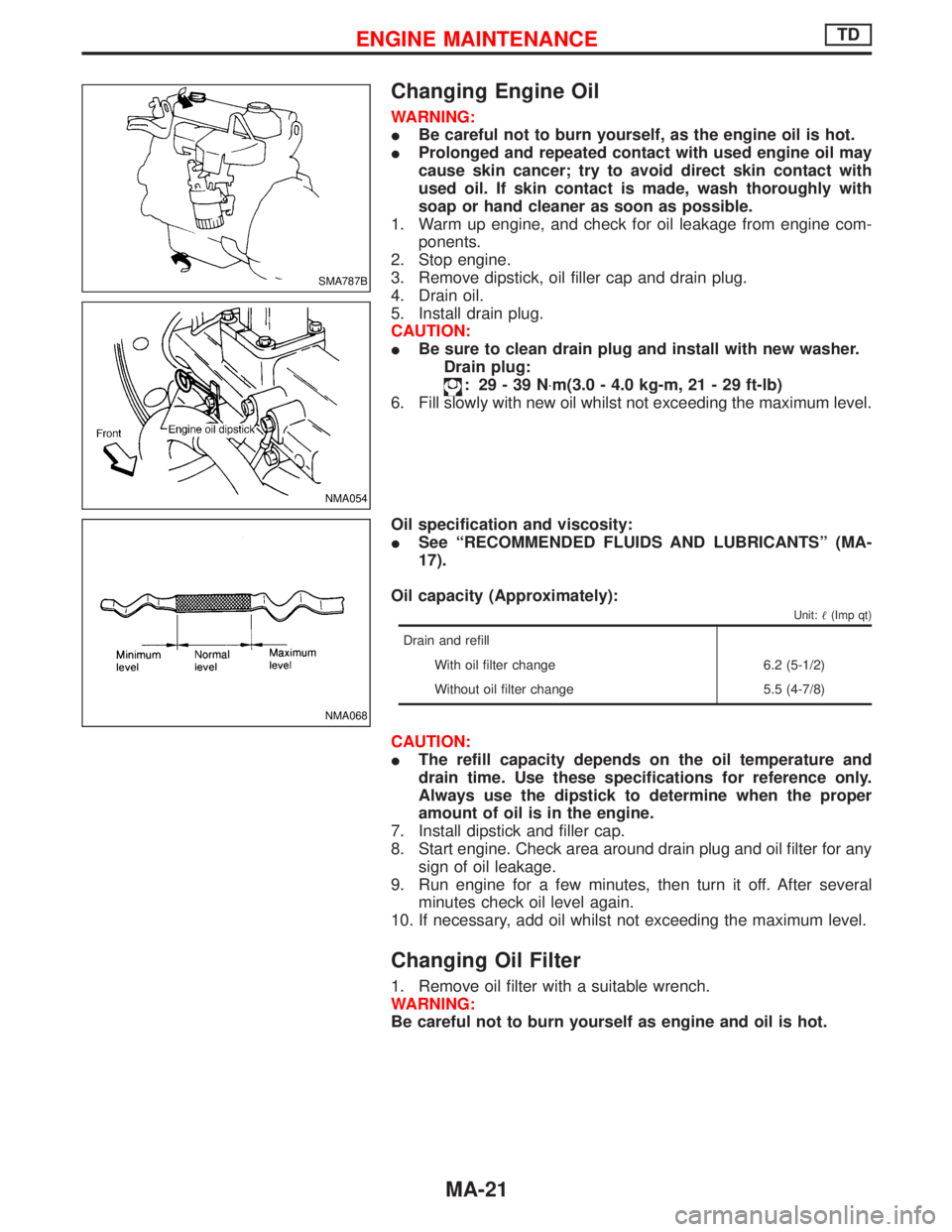
Changing Engine Oil
WARNING:
IBe careful not to burn yourself, as the engine oil is hot.
IProlonged and repeated contact with used engine oil may
cause skin cancer; try to avoid direct skin contact with
used oil. If skin contact is made, wash thoroughly with
soap or hand cleaner as soon as possible.
1. Warm up engine, and check for oil leakage from engine com-
ponents.
2. Stop engine.
3. Remove dipstick, oil filler cap and drain plug.
4. Drain oil.
5. Install drain plug.
CAUTION:
IBe sure to clean drain plug and install with new washer.
Drain plug:
: 29-39N×m(3.0 - 4.0 kg-m, 21 - 29 ft-lb)
6. Fill slowly with new oil whilst not exceeding the maximum level.
Oil specification and viscosity:
ISee ªRECOMMENDED FLUIDS AND LUBRICANTSº (MA-
17).
Oil capacity (Approximately):
Unit:(Imp qt)
Drain and refill
With oil filter change 6.2 (5-1/2)
Without oil filter change 5.5 (4-7/8)
CAUTION:
IThe refill capacity depends on the oil temperature and
drain time. Use these specifications for reference only.
Always use the dipstick to determine when the proper
amount of oil is in the engine.
7. Install dipstick and filler cap.
8. Start engine. Check area around drain plug and oil filter for any
sign of oil leakage.
9. Run engine for a few minutes, then turn it off. After several
minutes check oil level again.
10. If necessary, add oil whilst not exceeding the maximum level.
Changing Oil Filter
1. Remove oil filter with a suitable wrench.
WARNING:
Be careful not to burn yourself as engine and oil is hot.
SMA787B
NMA054
NMA068
ENGINE MAINTENANCETD
MA-21
Page 1481 of 1767
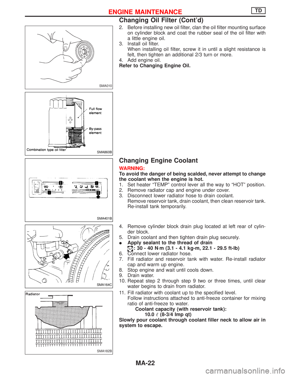
2. Before installing new oil filter, clan the oil filter mounting surface
on cylinder block and coat the rubber seal of the oil filter with
a little engine oil.
3. Install oil filter.
When installing oil filter, screw it in until a slight resistance is
felt, then tighten an additional 2/3 turn or more.
4. Add engine oil.
Refer to Changing Engine Oil.
Changing Engine Coolant
WARNING:
To avoid the danger of being scalded, never attempt to change
the coolant when the engine is hot.
1. Set heater ªTEMPº control lever all the way to ªHOTº position.
2. Remove radiator cap and engine under cover.
3. Disconnect lower radiator hose to drain coolant.
Remove reservoir tank, drain coolant, then clean reservoir tank.
Re-install tank temporarily.
4. Remove cylinder block drain plug located at left rear of cylin-
der block.
5. Drain coolant and then tighten drain plug securely.
IApply sealant to the thread of drain
:30-40N×m (3.1 - 4.1 kg-m, 22.1 - 29.5 ft-lb)
6. Connect lower radiator hose.
7. Fill radiator and reservoir tank with water. Re-install radiator
cap and warm up engine.
8. Stop engine and wait until cools down.
9. Drain water.
10. Repeat step 2 through step 9 two or three times, until clear
water begins to drain from radiator.
11. Fill radiator with coolant up to the specified level.
Follow instructions attached to anti-freeze container for mixing
ratio of anti-freeze to water.
Coolant capacity (with reservoir tank):
10.0(8-3/4 Imp qt)
Slowly pour coolant through coolant filler neck to allow air in
system to escape.
SMA010
SMA860B
SMA401B
SMA164C
SMA182B
ENGINE MAINTENANCETD
Changing Oil Filter (Cont'd)
MA-22
Page 1489 of 1767
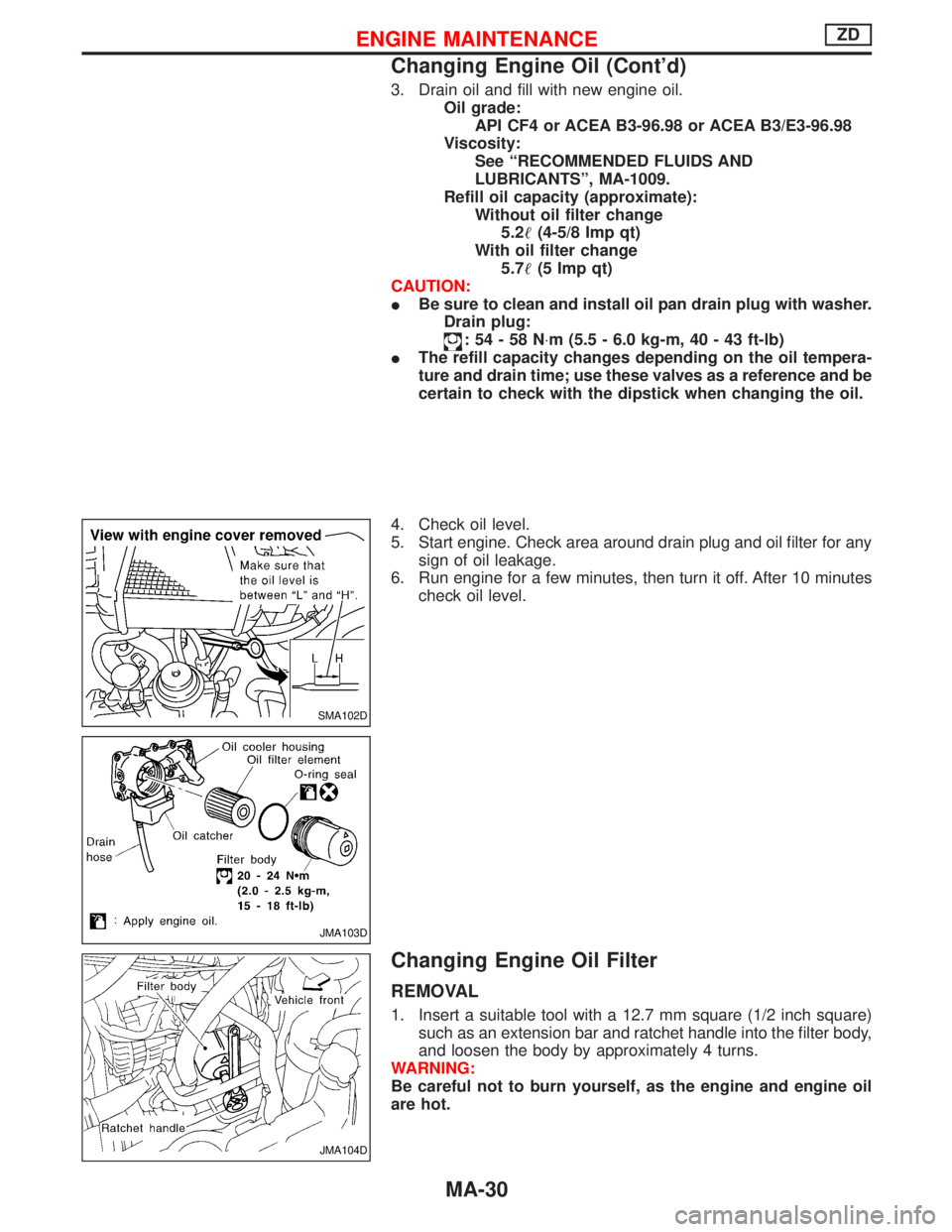
3. Drain oil and fill with new engine oil.
Oil grade:
API CF4 or ACEA B3-96.98 or ACEA B3/E3-96.98
Viscosity:
See ªRECOMMENDED FLUIDS AND
LUBRICANTSº, MA-1009.
Refill oil capacity (approximate):
Without oil filter change
5.2(4-5/8 Imp qt)
With oil filter change
5.7(5 Imp qt)
CAUTION:
IBe sure to clean and install oil pan drain plug with washer.
Drain plug:
:54-58N×m (5.5 - 6.0 kg-m, 40 - 43 ft-lb)
IThe refill capacity changes depending on the oil tempera-
ture and drain time; use these valves as a reference and be
certain to check with the dipstick when changing the oil.
4. Check oil level.
5. Start engine. Check area around drain plug and oil filter for any
sign of oil leakage.
6. Run engine for a few minutes, then turn it off. After 10 minutes
check oil level.
Changing Engine Oil Filter
REMOVAL
1. Insert a suitable tool with a 12.7 mm square (1/2 inch square)
such as an extension bar and ratchet handle into the filter body,
and loosen the body by approximately 4 turns.
WARNING:
Be careful not to burn yourself, as the engine and engine oil
are hot.
SMA102D
JMA103D
JMA104D
ENGINE MAINTENANCEZD
Changing Engine Oil (Cont'd)
MA-30
Page 1490 of 1767
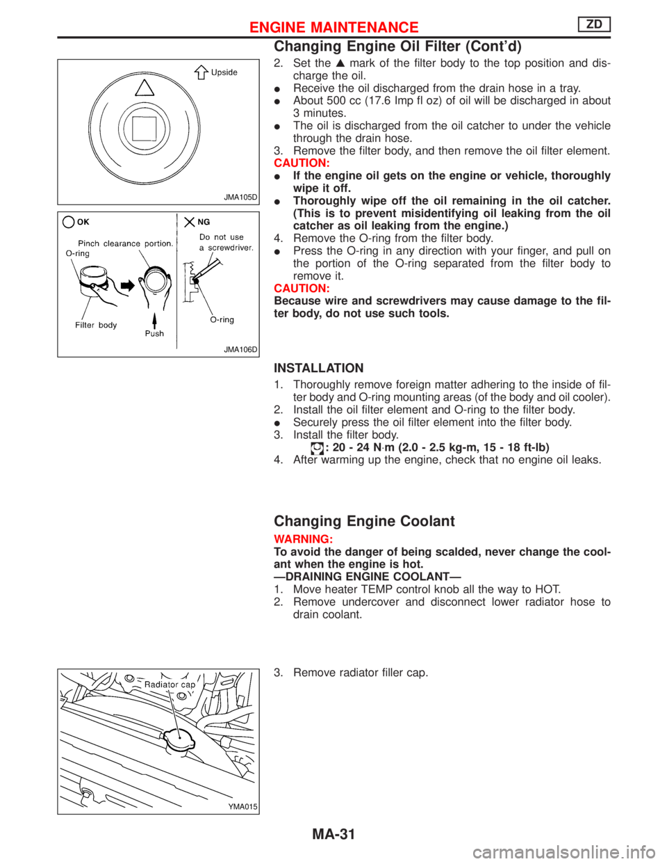
2. Set theGmark of the filter body to the top position and dis-
charge the oil.
IReceive the oil discharged from the drain hose in a tray.
IAbout 500 cc (17.6 Imp fl oz) of oil will be discharged in about
3 minutes.
IThe oil is discharged from the oil catcher to under the vehicle
through the drain hose.
3. Remove the filter body, and then remove the oil filter element.
CAUTION:
IIf the engine oil gets on the engine or vehicle, thoroughly
wipe it off.
IThoroughly wipe off the oil remaining in the oil catcher.
(This is to prevent misidentifying oil leaking from the oil
catcher as oil leaking from the engine.)
4. Remove the O-ring from the filter body.
IPress the O-ring in any direction with your finger, and pull on
the portion of the O-ring separated from the filter body to
remove it.
CAUTION:
Because wire and screwdrivers may cause damage to the fil-
ter body, do not use such tools.
INSTALLATION
1. Thoroughly remove foreign matter adhering to the inside of fil-
ter body and O-ring mounting areas (of the body and oil cooler).
2. Install the oil filter element and O-ring to the filter body.
ISecurely press the oil filter element into the filter body.
3. Install the filter body.
:20-24N×m (2.0 - 2.5 kg-m, 15 - 18 ft-lb)
4. After warming up the engine, check that no engine oil leaks.
Changing Engine Coolant
WARNING:
To avoid the danger of being scalded, never change the cool-
ant when the engine is hot.
ÐDRAINING ENGINE COOLANTÐ
1. Move heater TEMP control knob all the way to HOT.
2. Remove undercover and disconnect lower radiator hose to
drain coolant.
3. Remove radiator filler cap.
JMA105D
JMA106D
YMA015
ENGINE MAINTENANCEZD
Changing Engine Oil Filter (Cont'd)
MA-31