Page 728 of 1767
DTC Confirmation Procedure B (For
Accelerator Sticking)
If DTC P0571 is displayed same time, cure it at first.
WITH CONSULT-II
1) Turn ignition switch to ªONº position.
2) Select ªDATA MONITORº mode with CONSULT-II.
3) Start engine and rev it up to above 1,300 rpm.
4) Depress brake pedal immediately after releasing accelerator
pedal and keep it at least 5 seconds.
WITHOUT CONSULT-II
1) Start engine and rev it up to above 1,300 rpm.
2) Depress brake pedal immediately after releasing accelerator
pedal and keep it at least 5 seconds.
3) Turn ignition switch to ªLOCKº position, wait at least 5 seconds
and then turn to ªONº position.
4) Perform ªDiagnostic Test Mode II (Self-diagnostic results)º with
ECM.
DTC P0120 ACCEL POS SENSORTD27Ti
EC-366
Page 738 of 1767

Component Description
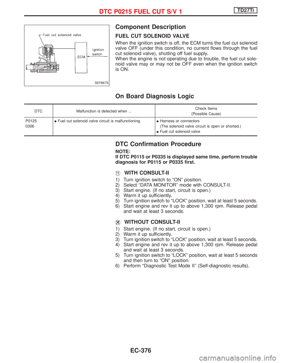
FUEL CUT SOLENOID VALVE
When the ignition switch is off, the ECM turns the fuel cut solenoid
valve OFF (under this condition, no current flows through the fuel
cut solenoid valve), shutting off fuel supply.
When the engine is not operating due to trouble, the fuel cut sole-
noid valve may or may not be OFF even when the ignition switch
is ON.
On Board Diagnosis Logic
DTC Malfunction is detected when ...Check Items
(Possible Cause)
P0125
0306IFuel cut solenoid valve circuit is malfunctioning.IHarness or connectors
(The solenoid valve circuit is open or shorted.)
IFuel cut solenoid valve
DTC Confirmation Procedure
NOTE:
If DTC P0115 or P0335 is displayed same time, perform trouble
diagnosis for P0115 or P0335 first.
WITH CONSULT-II
1) Turn ignition switch to ªONº position.
2) Select ªDATA MONITORº mode with CONSULT-II.
3) Start engine. (If no start, circuit is open.)
4) Warm it up sufficiently.
5) Turn ignition switch to ªLOCKº position, wait at least 5 seconds.
6) Start engine and rev it up to above 1,300 rpm. Release pedal
and wait at least 3 seconds.
WITHOUT CONSULT-II
1) Start engine. (If no start, circuit is open.)
2) Warm it up sufficiently.
3) Turn ignition switch to ªLOCKº position, wait at least 5 seconds.
4) Start engine and rev it up to above 1,300 rpm. Release pedal
and wait at least 3 seconds.
5) Turn ignition switch to ªLOCKº position, wait at least 5 seconds
and then turn to ªONº position.
6) Perform ªDiagnostic Test Mode IIº (Self-diagnostic results).
SEF667S
DTC P0215 FUEL CUT S/V 1TD27Ti
EC-376
Page 743 of 1767
DTC P1246 Confirmation Procedure
NOTE:
If both DTC P1246 and P1240 or P0335 are displayed, perform
TROUBLE DIAGNOSIS FOR DTC P1240 or P0335. (See EC-427
or EC-385.)
WITH CONSULT-II
1) Turn ignition switch to ªONº position and select ªDATA MONI-
TORº mode with CONSULT-II.
2) Start engine. Run it for 10 seconds at idle.
WITHOUT CONSULT-II
1) Start engine. Run it for 10 seconds at idle.
2) Turn ignition switch to ªLOCKº position, wait at least 5 seconds
and then turn to ªONº position.
3) Perform ªDiagnostic Test Mode IIº (Self-diagnostic results).
NOTE:
If a malfunction occurs intermittently, conduct suitable driving
pattern for 10 minutes. This makes it possible to determine
DTC.
DTC P0216 INJ TIMING CONT/V, DTC P1246 F/INJ TIMG F/BTD27Ti
EC-381
Page 747 of 1767

Component Description
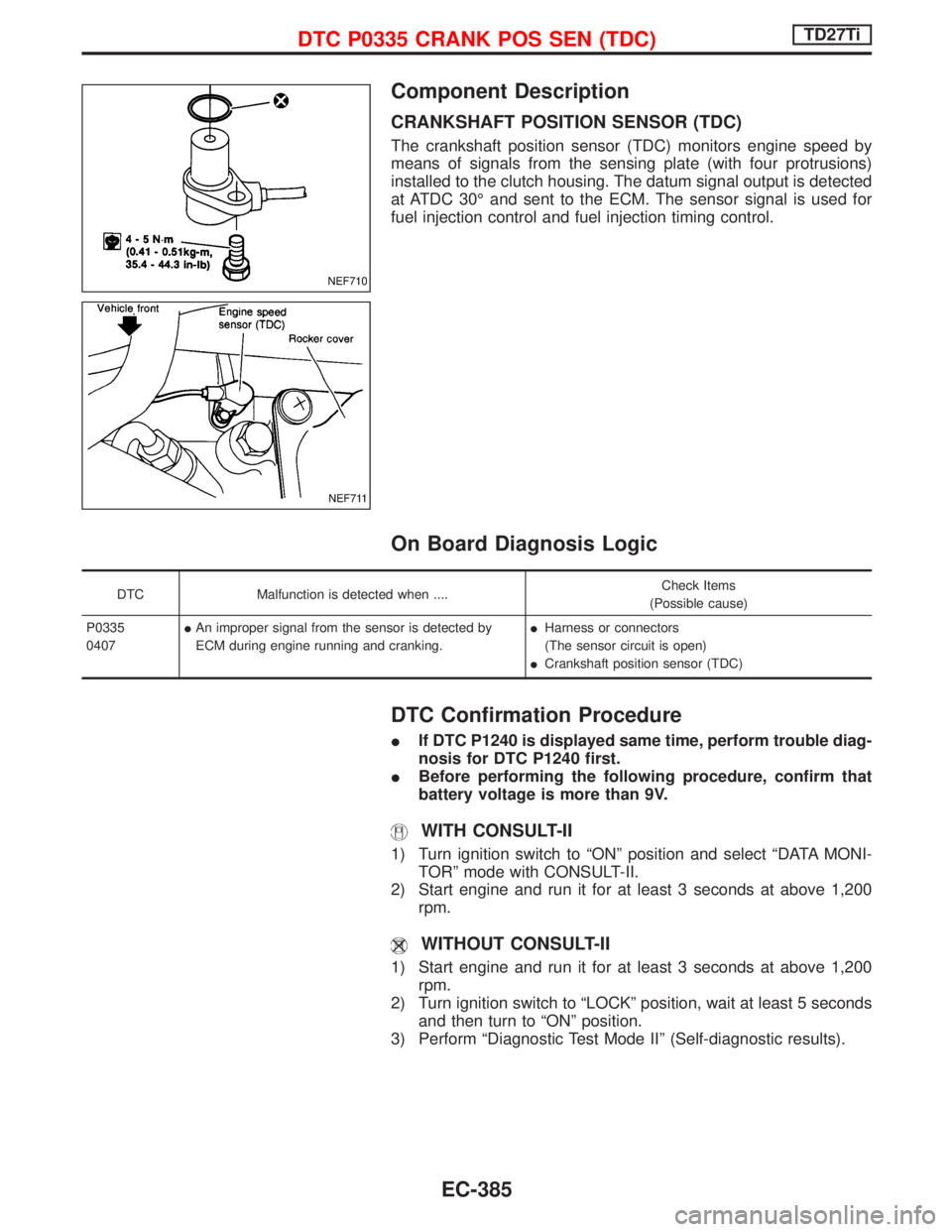
CRANKSHAFT POSITION SENSOR (TDC)
The crankshaft position sensor (TDC) monitors engine speed by
means of signals from the sensing plate (with four protrusions)
installed to the clutch housing. The datum signal output is detected
at ATDC 30É and sent to the ECM. The sensor signal is used for
fuel injection control and fuel injection timing control.
On Board Diagnosis Logic
DTC Malfunction is detected when ....Check Items
(Possible cause)
P0335
0407IAn improper signal from the sensor is detected by
ECM during engine running and cranking.IHarness or connectors
(The sensor circuit is open)
ICrankshaft position sensor (TDC)
DTC Confirmation Procedure
IIf DTC P1240 is displayed same time, perform trouble diag-
nosis for DTC P1240 first.
IBefore performing the following procedure, confirm that
battery voltage is more than 9V.
WITH CONSULT-II
1) Turn ignition switch to ªONº position and select ªDATA MONI-
TORº mode with CONSULT-II.
2) Start engine and run it for at least 3 seconds at above 1,200
rpm.
WITHOUT CONSULT-II
1) Start engine and run it for at least 3 seconds at above 1,200
rpm.
2) Turn ignition switch to ªLOCKº position, wait at least 5 seconds
and then turn to ªONº position.
3) Perform ªDiagnostic Test Mode IIº (Self-diagnostic results).
NEF710
NEF711
DTC P0335 CRANK POS SEN (TDC)TD27Ti
EC-385
Page 770 of 1767
Diagnostic Procedure
INSPECTION START
With CONSULT-II
1. Turn ignition switch ªONº.
2. Select ªSELF DIAG RESULTSº mode
with CONSULT-II.
3. Touch ªERASEº.
4. Perform ªDTC Confirmation Procedureº,
EC-407 again.
5. Is the DTC P1107 displayed again?
Without CONSULT-II
1. Turn ignition switch ªONº.
2. Erase the Diagnostic Test Mode II (Self-
diagnostic results) memory.
3. Perform ªDTC Confirmation Procedureº,
EC-407 again.
4. Perform ªDiagnostic Test Mode II (Self-
diagnostic results)º.
5. Is the DTC 0802 displayed again?
No
EYe s
Replace ECM.
INSPECTION END
H
H
DTC P1107 ECM 10TD27Ti
EC-408
Page 798 of 1767

Diagnostic Procedure
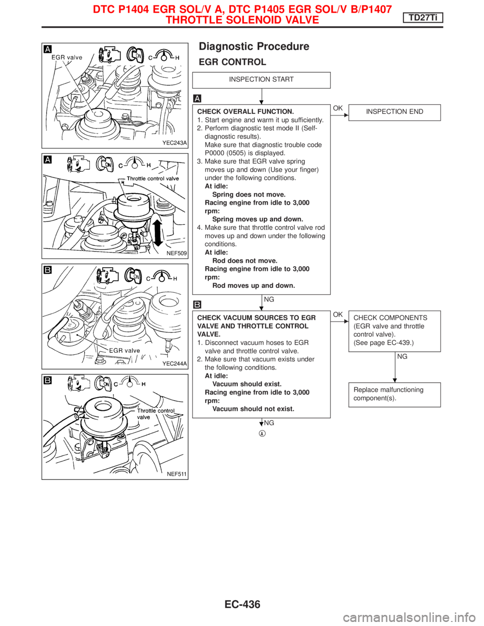
EGR CONTROL
INSPECTION START
CHECK OVERALL FUNCTION.
1. Start engine and warm it up sufficiently.
2. Perform diagnostic test mode II (Self-
diagnostic results).
Make sure that diagnostic trouble code
P0000 (0505) is displayed.
3. Make sure that EGR valve spring
moves up and down (Use your finger)
under the following conditions.
At idle:
Spring does not move.
Racing engine from idle to 3,000
rpm:
Spring moves up and down.
4. Make sure that throttle control valve rod
moves up and down under the following
conditions.
At idle:
Rod does not move.
Racing engine from idle to 3,000
rpm:
Rod moves up and down.
NG
EOK
INSPECTION END
CHECK VACUUM SOURCES TO EGR
VALVE AND THROTTLE CONTROL
VA LV E .
1. Disconnect vacuum hoses to EGR
valve and throttle control valve.
2. Make sure that vacuum exists under
the following conditions.
At idle:
Vacuum should exist.
Racing engine from idle to 3,000
rpm:
Vacuum should not exist.
NG
EOK
CHECK COMPONENTS
(EGR valve and throttle
control valve).
(See page EC-439.)
NG
Replace malfunctioning
component(s).
qA
YEC243A
NEF509
YEC244A
NEF511
H
H
H
H
DTC P1404 EGR SOL/V A, DTC P1405 EGR SOL/V B/P1407
THROTTLE SOLENOID VALVETD27Ti
EC-436
Page 807 of 1767
Diagnostic Procedure
INSPECTION START
With CONSULT-II
1. Turn ignition switch ªONº.
2. Select ªSELF DIAG RESULTSº mode
with CONSULT-II.
3. Touch ªERASEº.
4. Perform ªDTC Confirmation Procedureº,
EC-444 again.
5. Is the DTC P1603 or P1607 displayed
again?
Without CONSULT-II
1. Turn ignition switch ªONº.
2. Erase the Diagnostic Test Mode II (Self-
diagnostic results) memory.
3. Perform ªDTC Confirmation Procedureº,
EC-444 again.
4. Perform ªDiagnostic Test Mode II (Self-
diagnostic results)º.
5. Is the DTC 0301 or 0901 displayed
again?
No
EYe s
Replace ECM.
INSPECTION END
H
H
DTC PD1603 ECM 12, DTC P1607 ECM2TD27Ti
EC-445
Page 892 of 1767

Combination Meter Self-Diagnosis
PERFORMING SELF-DIAGNOSIS MODE
1. Turn the ignition switch to the ªLOCKº position.
2. Press both reset buttons on the combination meter and keep
them depressed.
3. Turn the ignition switch to the ªONº position, while keeping the
reset buttons pressed.
4. Release both reset buttons then self-diagnosis will start. The
sequence (A to I) is activated by press the either reset buttons.
NOTE:
If either reset button is not pressed for 20 seconds at each step or
if the ignition switch is turned OFF, the self-diagnosis mode is
exited.
Check items Display Remarks
A) Odometer segment test All odo trip meter segments are ON.
B) Software code
NEL735
This information is not used for service. Please skip this
step.
C) EEPROM code
NEL736
This information is not used for service. Please skip this
step.
D) Hardware code
NEL737
This information is not used for service. Please skip this
step.
E) PCB code
NEL738
This information is not used for service. Please skip this
step.
F)Meter/gauge test
(Sweeping movement)
SEL440X
Tachometer, speedometer, fuel level gauge and water tem-
perature gauge have sweeping movement test.
(The meter/gauges operate MIN.,MAX., MAX.,MIN. for
2 times)
The odo trip meter segment flashes during the sweep move-
ment.
G)Error 1
(Bit 0 - Bit 3)
SEL441X
The segment of each bit displays ª0º, meaning no failure. If
the bit(s) displays figures other than ª0º, the item of the bit
has failed.
For details, refer to ªFailure chart for Error 1 and Error Eº
below.
H)Error E
(Bit 4 - Bit 7)
SEL442X
METER AND GAUGES
EL-76