2002 NISSAN TERRANO Electrical system
[x] Cancel search: Electrical systemPage 1 of 1767

Edition: February 2002
Release: February 2002 (01)
Publication No.: SM2E00-1R20E0E
GENERAL INFORMATIONGI
MAINTENANCEMA
ENGINE MECHANICALEM
ENGINE LUBRICATION &
COOLING SYSTEMSLC
ENGINE CONTROL SYSTEMEC
ACCELERATOR CONTROL,
FUEL & EXHAUST SYSTEMFE
CLUTCHCL
MANUAL TRANSMISSIONMT
AUTOMATIC TRANSMISSIONAT
TRANSFERTF
PROPELLER SHAFT &
DIFFERENTIAL CARRIERPD
FRONT AXLE & FRONT SUSPENSIONFA
REAR AXLE & REAR SUSPENSIONRA
BRAKE SYSTEMBR
STEERING SYSTEMST
RESTRAINT SYSTEMRS
BODY & TRIMBT
HEATER & AIR CONDITIONERHA
STARTING & CHARGING SYSTEMSSC
ELECTRICAL SYSTEMEL
ALPHABETICAL INDEXIDX
TERRANO
MODEL R20 SERIES
NISSAN EUROPE N.V.
NISSAN EUROPE N.V.
Produced in The Netherlands
QUICK REFERENCE INDEX
Page 3 of 1767
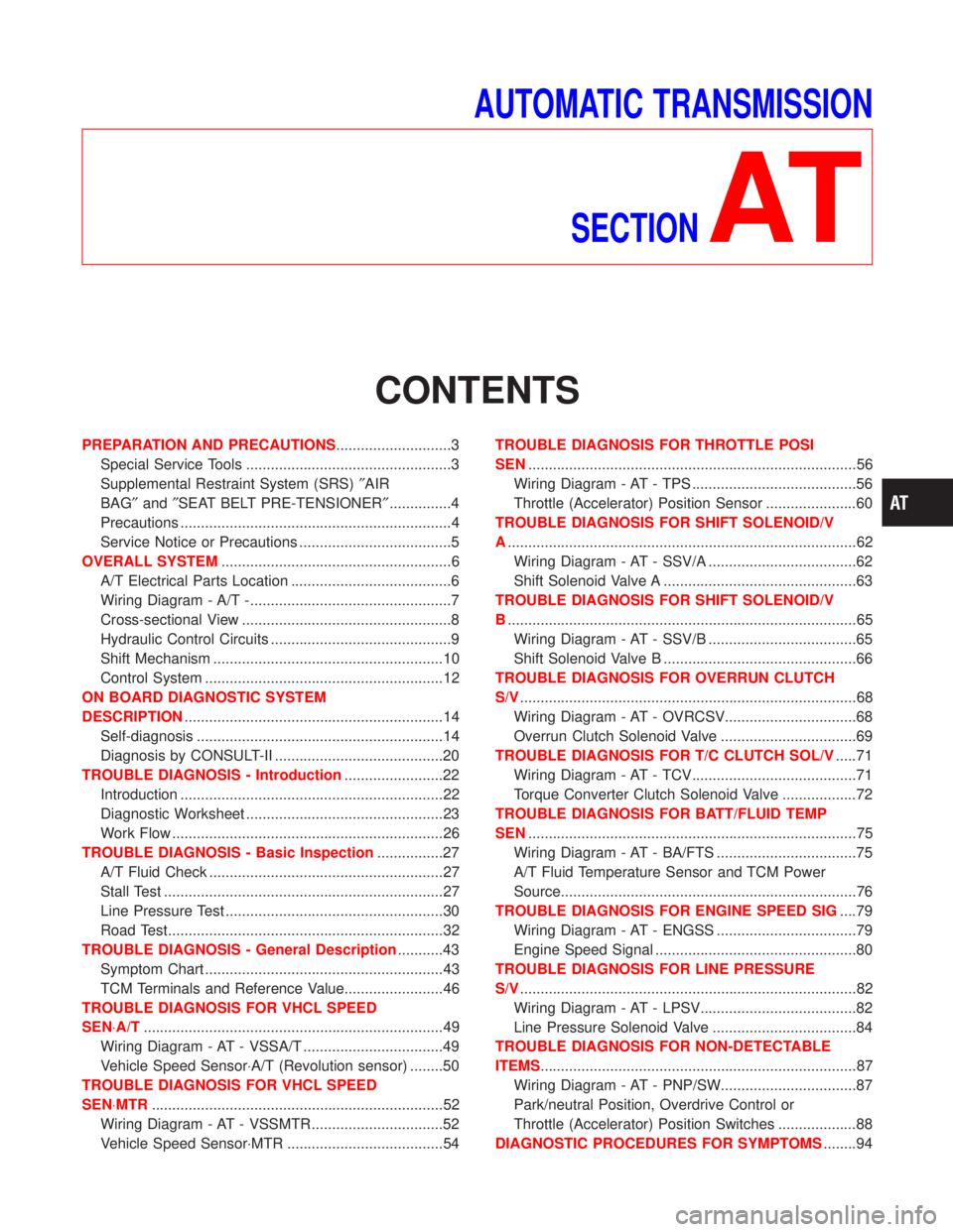
AUTOMATIC TRANSMISSION
SECTION
AT
CONTENTS
PREPARATION AND PRECAUTIONS............................3
Special Service Tools ..................................................3
Supplemental Restraint System (SRS)²AIR
BAG²and²SEAT BELT PRE-TENSIONER²...............4
Precautions ..................................................................4
Service Notice or Precautions .....................................5
OVERALL SYSTEM........................................................6
A/T Electrical Parts Location .......................................6
Wiring Diagram - A/T -.................................................7
Cross-sectional View ...................................................8
Hydraulic Control Circuits ............................................9
Shift Mechanism ........................................................10
Control System ..........................................................12
ON BOARD DIAGNOSTIC SYSTEM
DESCRIPTION...............................................................14
Self-diagnosis ............................................................14
Diagnosis by CONSULT-II .........................................20
TROUBLE DIAGNOSIS - Introduction........................22
Introduction ................................................................22
Diagnostic Worksheet ................................................23
Work Flow ..................................................................26
TROUBLE DIAGNOSIS - Basic Inspection................27
A/T Fluid Check .........................................................27
Stall Test ....................................................................27
Line Pressure Test .....................................................30
Road Test...................................................................32
TROUBLE DIAGNOSIS - General Description...........43
Symptom Chart ..........................................................43
TCM Terminals and Reference Value........................46
TROUBLE DIAGNOSIS FOR VHCL SPEED
SEN×A/T.........................................................................49
Wiring Diagram - AT - VSSA/T ..................................49
Vehicle Speed Sensor×A/T (Revolution sensor) ........50
TROUBLE DIAGNOSIS FOR VHCL SPEED
SEN×MTR.......................................................................52
Wiring Diagram - AT - VSSMTR ................................52
Vehicle Speed Sensor×MTR ......................................54TROUBLE DIAGNOSIS FOR THROTTLE POSI
SEN................................................................................56
Wiring Diagram - AT - TPS ........................................56
Throttle (Accelerator) Position Sensor ......................60
TROUBLE DIAGNOSIS FOR SHIFT SOLENOID/V
A.....................................................................................62
Wiring Diagram - AT - SSV/A ....................................62
Shift Solenoid Valve A ...............................................63
TROUBLE DIAGNOSIS FOR SHIFT SOLENOID/V
B.....................................................................................65
Wiring Diagram - AT - SSV/B ....................................65
Shift Solenoid Valve B ...............................................66
TROUBLE DIAGNOSIS FOR OVERRUN CLUTCH
S/V..................................................................................68
Wiring Diagram - AT - OVRCSV................................68
Overrun Clutch Solenoid Valve .................................69
TROUBLE DIAGNOSIS FOR T/C CLUTCH SOL/V.....71
Wiring Diagram - AT - TCV........................................71
Torque Converter Clutch Solenoid Valve ..................72
TROUBLE DIAGNOSIS FOR BATT/FLUID TEMP
SEN................................................................................75
Wiring Diagram - AT - BA/FTS ..................................75
A/T Fluid Temperature Sensor and TCM Power
Source........................................................................76
TROUBLE DIAGNOSIS FOR ENGINE SPEED SIG....79
Wiring Diagram - AT - ENGSS ..................................79
Engine Speed Signal .................................................80
TROUBLE DIAGNOSIS FOR LINE PRESSURE
S/V..................................................................................82
Wiring Diagram - AT - LPSV......................................82
Line Pressure Solenoid Valve ...................................84
TROUBLE DIAGNOSIS FOR NON-DETECTABLE
ITEMS.............................................................................87
Wiring Diagram - AT - PNP/SW.................................87
Park/neutral Position, Overdrive Control or
Throttle (Accelerator) Position Switches ...................88
DIAGNOSTIC PROCEDURES FOR SYMPTOMS........94
Page 6 of 1767
Supplemental Restraint System (SRS) ªAIR
BAGº and ªSEAT BELT PRE-TENSIONERº
The Supplemental Restraint System such as ªAIR BAGº and ªSEAT BELT PRE-TENSIONERº used along with
a seat belt, helps to reduce the risk or severity of injury to the driver and front passenger in a frontal collision.
The SRS system composition which is available to NISSAN MODEL R20 is as follows (The composition var-
ies according to the destination.):
Driver air bag module (located in the center of the steering wheel), front passenger air bag module (located
on the instrument panel on passenger side), seat belt pre-tensioner, a diagnosis sensor unit, warning lamp,
wiring harness and spiral cable.
Information necessary to service the system safely is included in theRS sectionof this Service Manual.
WARNING:
ITo avoid rendering the SRS inoperative, which could increase the risk of personal injury or death
in the event of a collision which would result in air bag inflation, all maintenance must be performed
by an authorized NISSAN dealer.
IImproper maintenance, including incorrect removal and installation of the SRS, can lead to per-
sonal injury caused by unintentional activation of the system. For removal of Spiral Cable and Air
Bag Module, see the RS section.
IDo not use electrical test equipment on any circuit related to the SRS unless instructed to in this
Service Manual. Spiral cable and wiring harnesses covered with yellow insulation either just before
the harness connectors or for the complete harness are related to the SRS.
Precautions
IBefore proceeding with disassembly, thoroughly clean the outside of the transmission. It is important to
prevent the internal parts from becoming contaminated by dirt or other foreign matter.
IDisassembly should be done in a clean work area.
IUse lint-free cloth or towels for wiping parts clean. Common shop rags can leave fibers that could inter-
fere with the operation of the transmission.
IPlace disassembled parts in order for easier and proper assembly.
IAll parts should be carefully cleaned with a general purpose, non-flammable solvent before inspection or
reassembly.
IGaskets, seals and O-rings should be replaced any time the transmission is disassembled.
IIt is very important to perform functional tests whenever they are indicated.
IThe valve body contains precision parts and requires extreme care when parts are removed and serviced.
Place removed parts in a parts rack in order to replace them in correct positions and sequences. Care will
also prevent springs and small parts from becoming scattered or lost.
IProperly installed valves, sleeves, plugs, etc. will slide along bores in valve body under their own weight.
IBefore assembly, apply a coat of recommended ATF to all parts. Apply petroleum jelly to protect O-rings
and seals, and to hold bearings and washers in place during assembly. Do not use grease.
IExtreme care should be taken to avoid damage to O-rings, seals and gaskets when assembling.
IAfter overhaul, refill the transmission with new ATF.
IWhen the A/T drain plug is removed, only some of the fluid is drained. Old A/T fluid will remain in torque
converter and ATF cooling system.
Always follow the procedures under ªChanging A/T Fluidº in the MA section when changing A/T fluid.
PREPARATION AND PRECAUTIONS
AT- 4
Page 8 of 1767
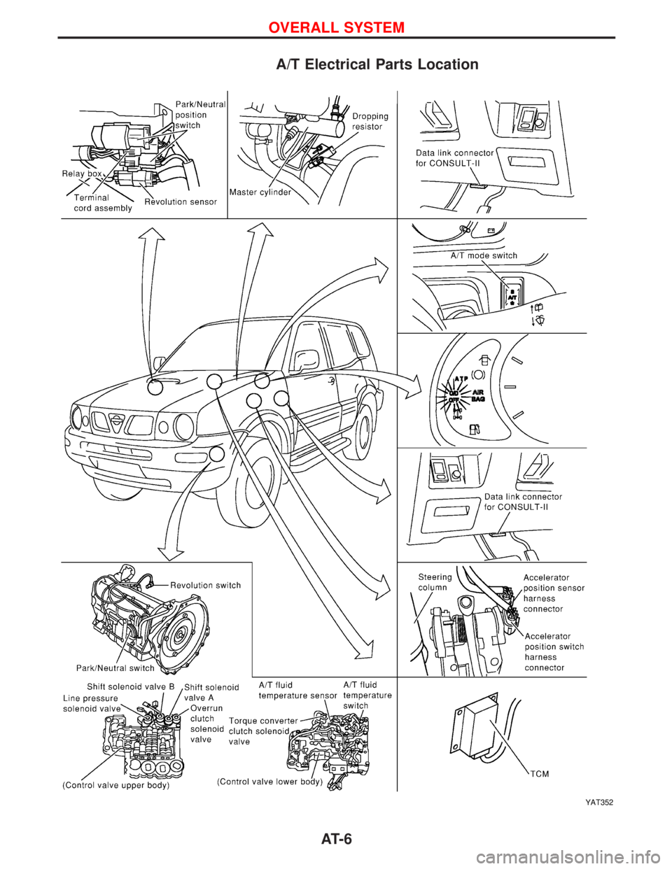
A/T Electrical Parts Location
YAT352
OVERALL SYSTEM
AT- 6
Page 22 of 1767
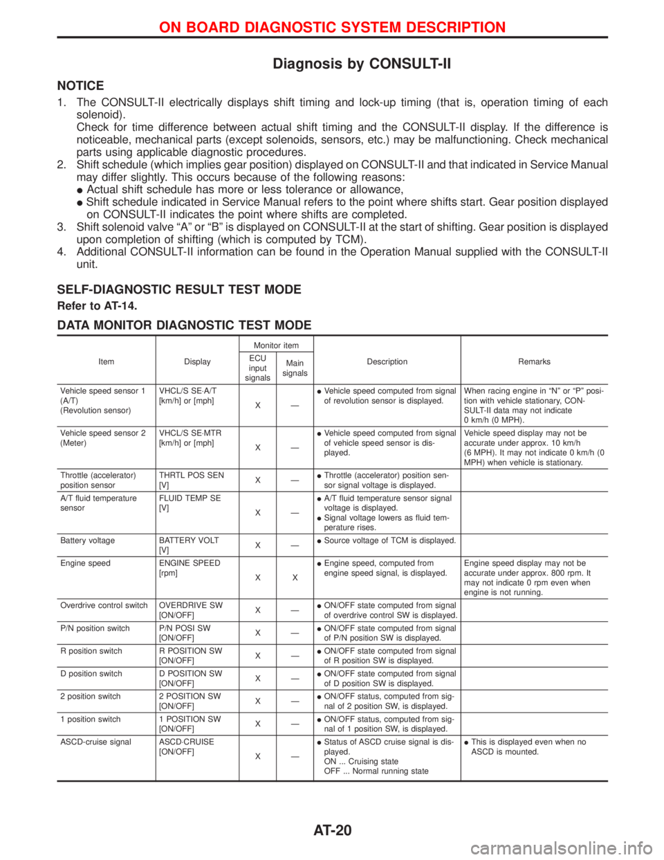
Diagnosis by CONSULT-II
NOTICE
1. The CONSULT-II electrically displays shift timing and lock-up timing (that is, operation timing of each
solenoid).
Check for time difference between actual shift timing and the CONSULT-II display. If the difference is
noticeable, mechanical parts (except solenoids, sensors, etc.) may be malfunctioning. Check mechanical
parts using applicable diagnostic procedures.
2. Shift schedule (which implies gear position) displayed on CONSULT-II and that indicated in Service Manual
may differ slightly. This occurs because of the following reasons:
IActual shift schedule has more or less tolerance or allowance,
IShift schedule indicated in Service Manual refers to the point where shifts start. Gear position displayed
on CONSULT-II indicates the point where shifts are completed.
3. Shift solenoid valve ªAº or ªBº is displayed on CONSULT-II at the start of shifting. Gear position is displayed
upon completion of shifting (which is computed by TCM).
4. Additional CONSULT-II information can be found in the Operation Manual supplied with the CONSULT-II
unit.
SELF-DIAGNOSTIC RESULT TEST MODE
Refer to AT-14.
DATA MONITOR DIAGNOSTIC TEST MODE
Item DisplayMonitor item
Description Remarks ECU
input
signalsMain
signals
Vehicle speed sensor 1
(A/T)
(Revolution sensor)VHCL/S SE×A/T
[km/h] or [mph]
XÐIVehicle speed computed from signal
of revolution sensor is displayed.When racing engine in ªNº or ªPº posi-
tion with vehicle stationary, CON-
SULT-II data may not indicate
0 km/h (0 MPH).
Vehicle speed sensor 2
(Meter)VHCL/S SE×MTR
[km/h] or [mph]
XÐIVehicle speed computed from signal
of vehicle speed sensor is dis-
played.Vehicle speed display may not be
accurate under approx. 10 km/h
(6 MPH). It may not indicate 0 km/h (0
MPH) when vehicle is stationary.
Throttle (accelerator)
position sensorTHRTL POS SEN
[V]XÐIThrottle (accelerator) position sen-
sor signal voltage is displayed.
A/T fluid temperature
sensorFLUID TEMP SE
[V]
XÐIA/T fluid temperature sensor signal
voltage is displayed.
ISignal voltage lowers as fluid tem-
perature rises.
Battery voltage BATTERY VOLT
[V]XÐISource voltage of TCM is displayed.
Engine speed ENGINE SPEED
[rpm]
XXIEngine speed, computed from
engine speed signal, is displayed.Engine speed display may not be
accurate under approx. 800 rpm. It
may not indicate 0 rpm even when
engine is not running.
Overdrive control switch OVERDRIVE SW
[ON/OFF]XÐION/OFF state computed from signal
of overdrive control SW is displayed.
P/N position switch P/N POSI SW
[ON/OFF]XÐION/OFF state computed from signal
of P/N position SW is displayed.
R position switch R POSITION SW
[ON/OFF]XÐION/OFF state computed from signal
of R position SW is displayed.
D position switch D POSITION SW
[ON/OFF]XÐION/OFF state computed from signal
of D position SW is displayed.
2 position switch 2 POSITION SW
[ON/OFF]XÐION/OFF status, computed from sig-
nal of 2 position SW, is displayed.
1 position switch 1 POSITION SW
[ON/OFF]XÐION/OFF status, computed from sig-
nal of 1 position SW, is displayed.
ASCD-cruise signal ASCD×CRUISE
[ON/OFF]
XÐIStatus of ASCD cruise signal is dis-
played.
ON ... Cruising state
OFF ... Normal running stateIThis is displayed even when no
ASCD is mounted.
ON BOARD DIAGNOSTIC SYSTEM DESCRIPTION
AT-20
Page 205 of 1767
Supplement Restraint System (SRS) ªAIR BAGº
and ªSEAT BELT PRE-TENSIONERº
The Supplemental Restraint System ªAir Bagº and ªSeat Belt Pre-tensionerº, used along with a seat belt, help
to reduce the risk or severity or injury to the driver and front passenger in a collision. The Supplemental
Restraint System consists of an air bag module (located in the center of the steering wheel and on the instru-
ment panel on the passenger side, where fitted), seat belt pre-tensioners, a diagnosis sensor unit, warning
lamp, wiring harness and spiral cable. Information necessary to service the system safely is included in the
BT sectionof this Service Manual.
WARNING:
ITo avoid rendering the SRS inoperative (which could increase the risk of personal injury or death
in the event of a collision which would result in air bag inflation), all maintenance must be per-
formed by an authorized NISSAN dealer.
IImproper maintenance, including incorrect removal and installation of the SRS, can lead to per-
sonal injury caused by unintentional activation of the system.
IDo not use electrical test equipment on any circuit related to the SRS unless instructed to in this
Service Manual. SRS wiring harnesses (except ªSEAT BELT-TENSIONERº connector) can be iden-
tified with yellow harness connector and with yellow harness protector or yellow insulation tape
before the harness connectors.
Precautions
IUse only ªDOT 4º fluid from a sealed container.
INever reuse drained brake fluid.
IBe careful not to splash brake fluid on painted areas; it
may cause paint damage. If brake fluid is splashed on
painted areas, wash it away with water immediately.
ITo clean master cylinder parts, disc brake caliper parts or
wheel cylinder parts, use clean brake fluid.
INever use mineral oils such as Petrol or kerosene. They
will ruin rubber parts of hydraulic system.
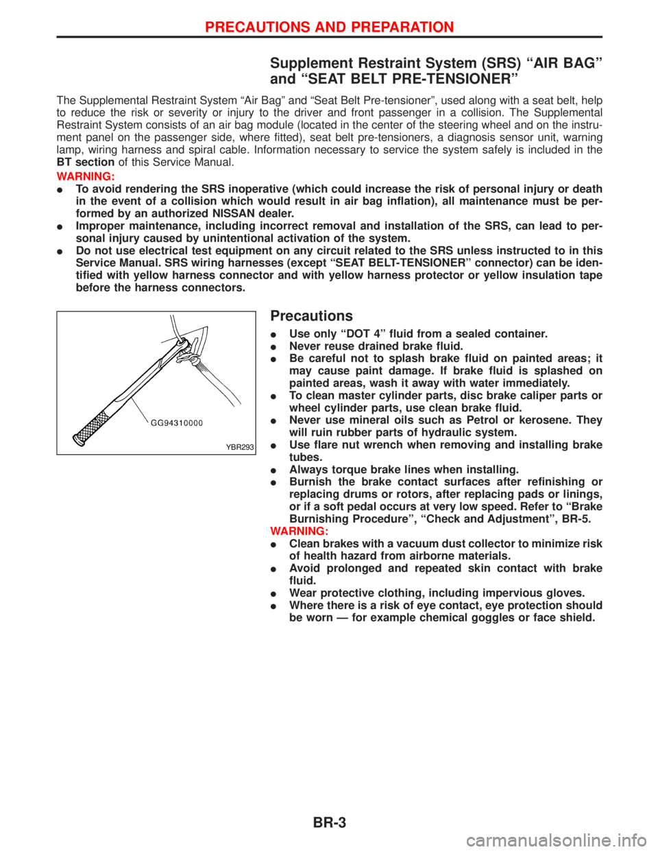
IUse flare nut wrench when removing and installing brake
tubes.
IAlways torque brake lines when installing.
IBurnish the brake contact surfaces after refinishing or
replacing drums or rotors, after replacing pads or linings,
or if a soft pedal occurs at very low speed. Refer to ªBrake
Burnishing Procedureº, ªCheck and Adjustmentº, BR-5.
WARNING:
IClean brakes with a vacuum dust collector to minimize risk
of health hazard from airborne materials.
IAvoid prolonged and repeated skin contact with brake
fluid.
IWear protective clothing, including impervious gloves.
IWhere there is a risk of eye contact, eye protection should
be worn Ð for example chemical goggles or face shield.
YBR293
PRECAUTIONS AND PREPARATION
BR-3
Page 240 of 1767
System Description
Sensor
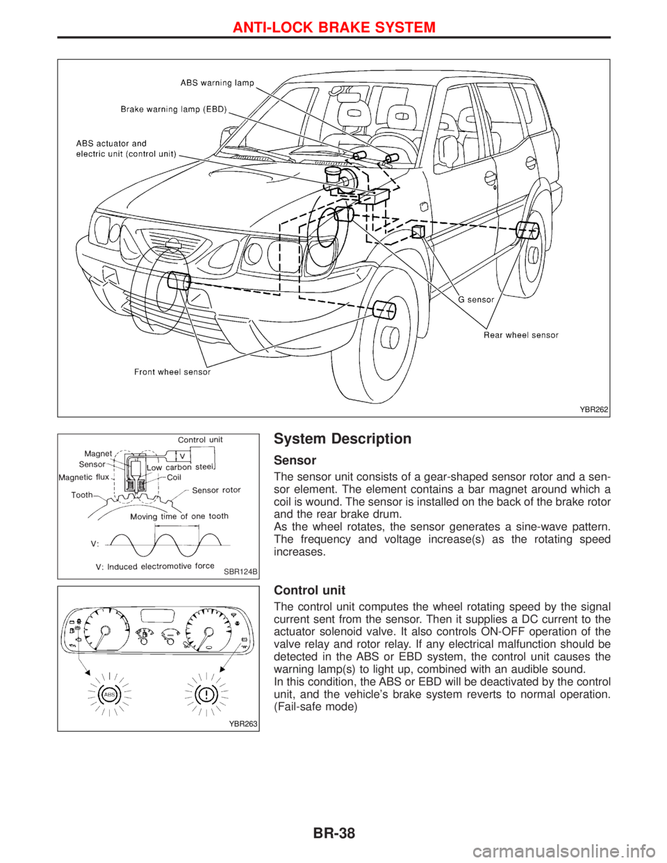
The sensor unit consists of a gear-shaped sensor rotor and a sen-
sor element. The element contains a bar magnet around which a
coil is wound. The sensor is installed on the back of the brake rotor
and the rear brake drum.
As the wheel rotates, the sensor generates a sine-wave pattern.
The frequency and voltage increase(s) as the rotating speed
increases.
Control unit
The control unit computes the wheel rotating speed by the signal
current sent from the sensor. Then it supplies a DC current to the
actuator solenoid valve. It also controls ON-OFF operation of the
valve relay and rotor relay. If any electrical malfunction should be
detected in the ABS or EBD system, the control unit causes the
warning lamp(s) to light up, combined with an audible sound.
In this condition, the ABS or EBD will be deactivated by the control
unit, and the vehicle's brake system reverts to normal operation.
(Fail-safe mode)
YBR262
SBR124B
YBR263
ANTI-LOCK BRAKE SYSTEM
BR-38
Page 247 of 1767
ACTUATOR
Removal
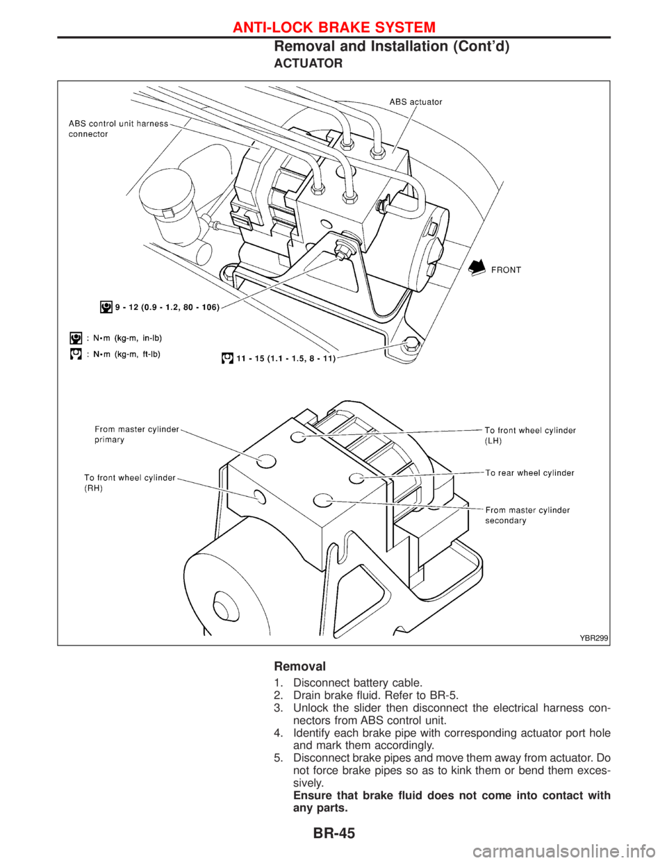
1. Disconnect battery cable.
2. Drain brake fluid. Refer to BR-5.
3. Unlock the slider then disconnect the electrical harness con-
nectors from ABS control unit.
4. Identify each brake pipe with corresponding actuator port hole
and mark them accordingly.
5. Disconnect brake pipes and move them away from actuator. Do
not force brake pipes so as to kink them or bend them exces-
sively.
Ensure that brake fluid does not come into contact with
any parts.
YBR299
ANTI-LOCK BRAKE SYSTEM
Removal and Installation (Cont'd)
BR-45