2002 NISSAN TERRANO tires
[x] Cancel search: tiresPage 859 of 1767
Bulb Replacement
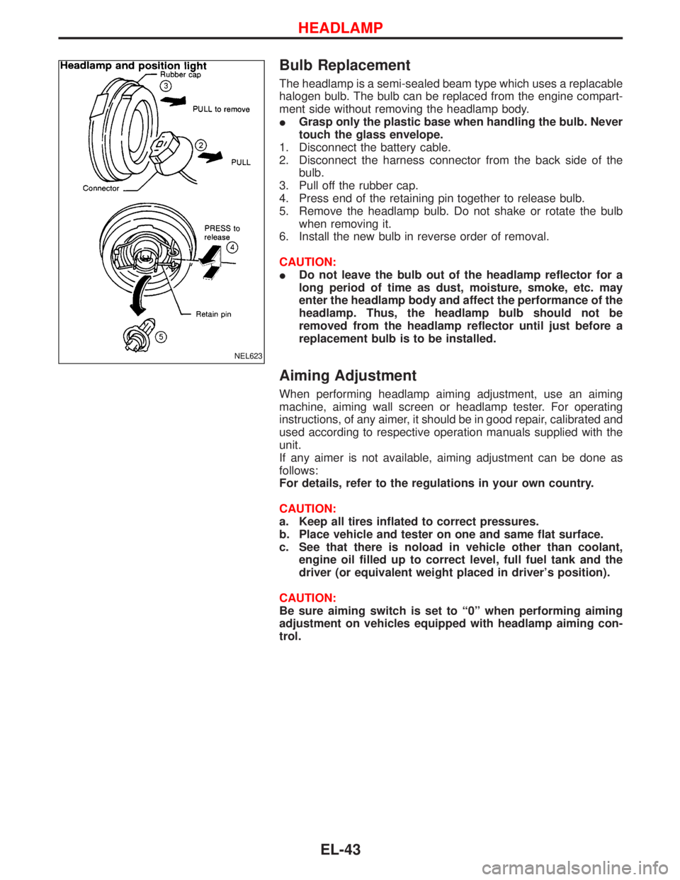
The headlamp is a semi-sealed beam type which uses a replacable
halogen bulb. The bulb can be replaced from the engine compart-
ment side without removing the headlamp body.
IGrasp only the plastic base when handling the bulb. Never
touch the glass envelope.
1. Disconnect the battery cable.
2. Disconnect the harness connector from the back side of the
bulb.
3. Pull off the rubber cap.
4. Press end of the retaining pin together to release bulb.
5. Remove the headlamp bulb. Do not shake or rotate the bulb
when removing it.
6. Install the new bulb in reverse order of removal.
CAUTION:
IDo not leave the bulb out of the headlamp reflector for a
long period of time as dust, moisture, smoke, etc. may
enter the headlamp body and affect the performance of the
headlamp. Thus, the headlamp bulb should not be
removed from the headlamp reflector until just before a
replacement bulb is to be installed.
Aiming Adjustment
When performing headlamp aiming adjustment, use an aiming
machine, aiming wall screen or headlamp tester. For operating
instructions, of any aimer, it should be in good repair, calibrated and
used according to respective operation manuals supplied with the
unit.
If any aimer is not available, aiming adjustment can be done as
follows:
For details, refer to the regulations in your own country.
CAUTION:
a. Keep all tires inflated to correct pressures.
b. Place vehicle and tester on one and same flat surface.
c. See that there is noload in vehicle other than coolant,
engine oil filled up to correct level, full fuel tank and the
driver (or equivalent weight placed in driver's position).
CAUTION:
Be sure aiming switch is set to ª0º when performing aiming
adjustment on vehicles equipped with headlamp aiming con-
trol.
NEL623
HEADLAMP
EL-43
Page 869 of 1767
Front Fog Lamp Aiming Adjustment
When performing fog lamp aiming adjustment, use an aiming
machine, aiming wall screen or headlamp tester. The aimer should
be in good operational condition, calibrated and used according to
the relevant operation manuals supplied with the unit.
If an aimer is not available, aiming adjustment can be done as fol-
lows:
For details, refer to the regulations in your own country.
CAUTION:
IKeep all tires inflated to correct pressures.
IPlace vehicle and tester on one and the same flat surface.
IEnsure that there is no-load in the vehicle other than
coolant, engine oil (filled up to correct level), full fuel tank
and the driver (or equivalent weight placed in driver's posi-
tion).
For details of front fog lamp aiming adjustment, refer to ªAiming
Adjustmentº, EL-43.
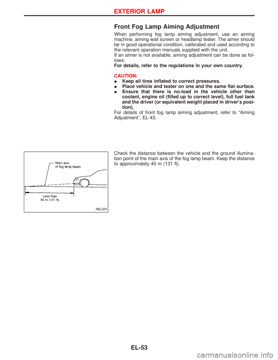
Check the distance between the vehicle and the ground illumina-
tion point of the main axis of the fog lamp beam. Keep the distance
to approximately 40 m (131 ft).
NEL331
EXTERIOR LAMP
EL-53
Page 1260 of 1767
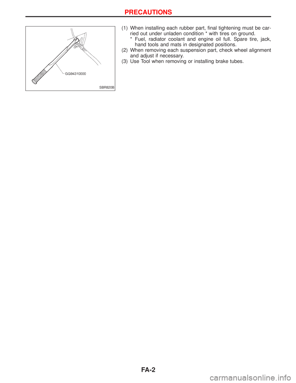
(1) When installing each rubber part, final tightening must be car-
ried out under unladen condition * with tires on ground.
* Fuel, radiator coolant and engine oil full. Spare tire, jack,
hand tools and mats in designated positions.
(2) When removing each suspension part, check wheel alignment
and adjust if necessary.
(3) Use Tool when removing or installing brake tubes.
SBR820B
PRECAUTIONS
FA-2
Page 1266 of 1767
Front Wheel Alignment
Before checking front wheel alignment, be sure to make a prelimi-
nary inspection.
PRELIMINARY INSPECTION
1. Check the tires for wear and proper inflation.
2. Check the wheel runout.
Wheel runout:
Refer to SDS, FA-39.
3. Check the front wheel bearings for looseness.
4. Check the front suspension for looseness.
5. Check the steering linkage for looseness.
6. Check that the front shock absorbers work properly by using
the standard bounce test.
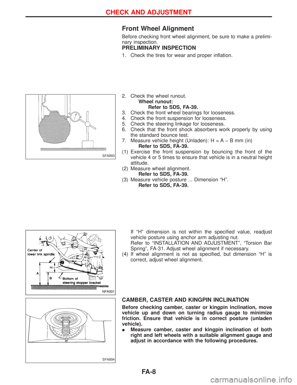
7. Measure vehicle height (Unladen): H = A þ B mm (in)
Refer to SDS, FA-39.
(1) Exercise the front suspension by bouncing the front of the
vehicle 4 or 5 times to ensure that vehicle is in a neutral height
attitude.
(2) Measure wheel alignment.
Refer to SDS, FA-39.
(3) Measure vehicle posture ... Dimension ªHº.
Refer to SDS, FA-39.
If ªHº dimension is not within the specified value, readjust
vehicle posture using anchor arm adjusting nut.
Refer to ªINSTALLATION AND ADJUSTMENTº, ªTorsion Bar
Springº, FA-31. Adjust wheel alignment if necessary.
(4) If wheel alignment is not as specified, but dimension ªHº is
correct, adjust wheel alignment.
CAMBER, CASTER AND KINGPIN INCLINATION
Before checking camber, caster or kingpin inclination, move
vehicle up and down on turning radius gauge to minimize
friction. Ensure that vehicle is in correct posture (unladen
vehicle).
IMeasure camber, caster and kingpin inclination of both
right and left wheels with a suitable alignment gauge and
adjust in accordance with the following procedures.
SFA893
NFA001
SFA894
CHECK AND ADJUSTMENT
FA-8
Page 1274 of 1767
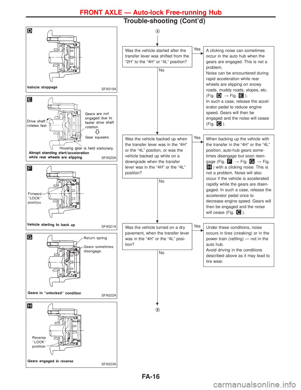
qA
Was the vehicle started after the
transfer lever was shifted from the
ª2Hº to the ª4Hº or ª4Lº position?
No
EYe s
A clicking noise can sometimes
occur in the auto hub when the
gears are engaged. This is not a
problem.
Noise can be encountered during
rapid acceleration while rear
wheels are slipping on snowy
roads, muddy roads, slopes, etc.
(Fig.
,Fig.).
In such a case, release the accel-
erator pedal to reduce engine
speed. Gears will then be
engaged and the noise will cease
(Fig.
).
Was the vehicle backed up when
the transfer lever was in the ª4Hº
or the ª4Lº position, or was the
vehicle backed up while on a
downgrade when the transfer
lever was in the ª4Hº or the ª4Lº
position?
No
EYe s
When backing up the vehicle with
the transfer in the ª4Hº or the ª4Lº
position, auto-hub gears some-
times disengage but soon reen-
gage (Fig.
,Fig.,Fig.
) with a clicking noise. This is
not a problem. Noise will also
occur if the vehicle is accelerated
rapidly while the gears are disen-
gaged. In such a case, release the
accelerator pedal once to
decrease engine speed. Gears will
then be engaged and the noise
will cease (Fig.
).
Was the vehicle turned on a dry
pavement, when the transfer lever
was in the ª4Hº or the ª4Lº posi-
tion?
No
EYe s
Under these conditions, noise
occurs in tires (creaking) or in the
power train (rattling) Ð not in the
auto hub.
Avoid driving in the conditions
described above as it may lead to
tire wear.
qB
SFA519A
SFA520A
SFA521A
SFA522A
SFA523A
H
H
H
H
FRONT AXLE Ð Auto-lock Free-running Hub
Trouble-shooting (Cont'd)
FA-16
Page 1290 of 1767
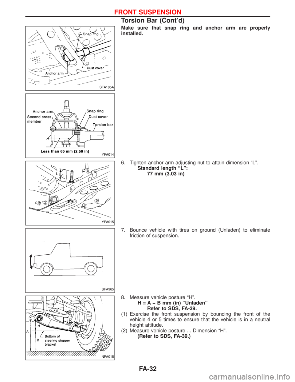
Make sure that snap ring and anchor arm are properly
installed.
6. Tighten anchor arm adjusting nut to attain dimension ªLº.
Standard length ªLº:
77 mm (3.03 in)
7. Bounce vehicle with tires on ground (Unladen) to eliminate
friction of suspension.
8. Measure vehicle posture ªHº.
H = A þ B mm (in) ªUnladenº
Refer to SDS, FA-39.
(1) Exercise the front suspension by bouncing the front of the
vehicle 4 or 5 times to ensure that the vehicle is in a neutral
height attitude.
(2) Measure vehicle posture ... Dimension ªHº.
(Refer to SDS, FA-39.)
SFA185A
YFA014
YFA015
SFA965
NFA015
FRONT SUSPENSION
Torsion Bar (Cont'd)
FA-32
Page 1292 of 1767
INSTALLATION
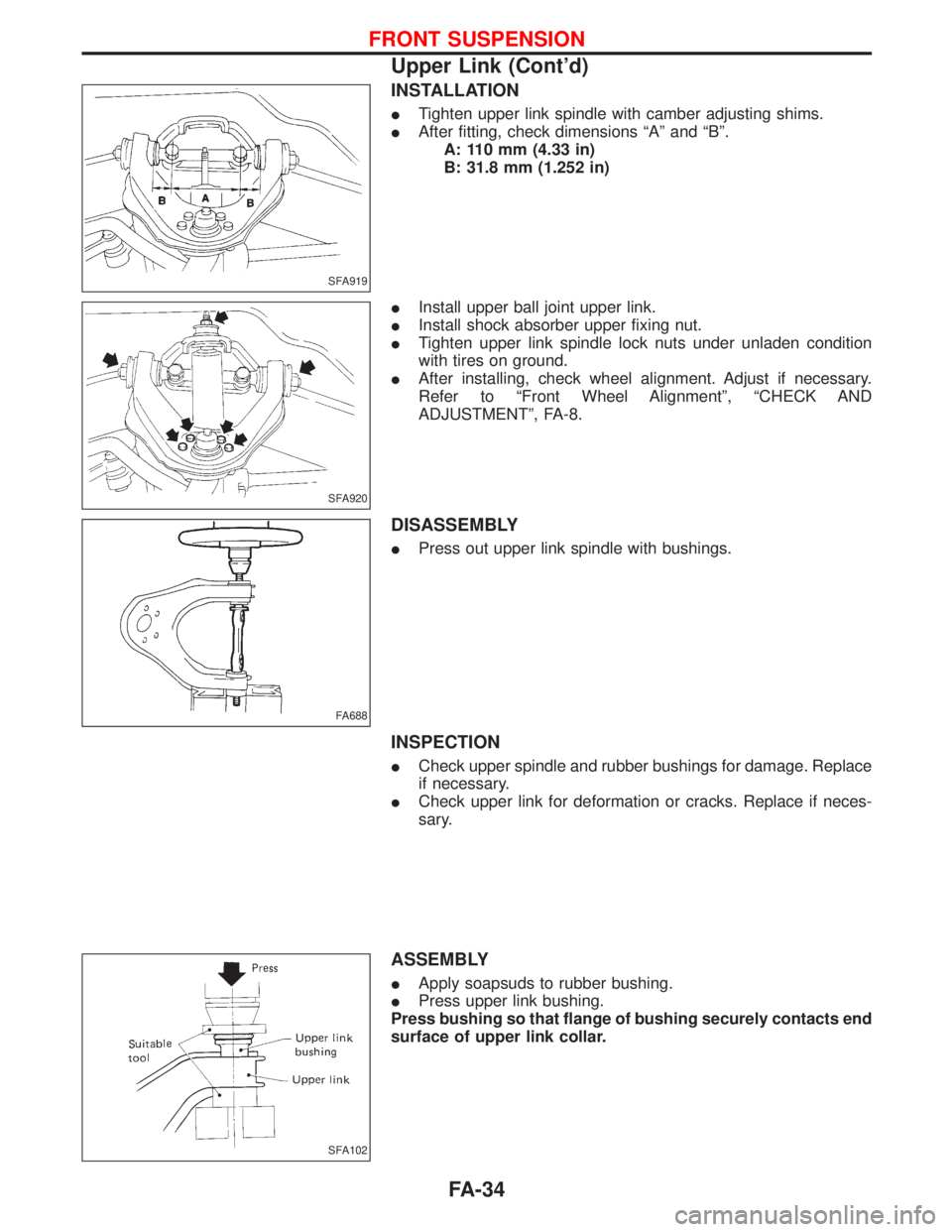
ITighten upper link spindle with camber adjusting shims.
IAfter fitting, check dimensions ªAº and ªBº.
A: 110 mm (4.33 in)
B: 31.8 mm (1.252 in)
IInstall upper ball joint upper link.
IInstall shock absorber upper fixing nut.
ITighten upper link spindle lock nuts under unladen condition
with tires on ground.
IAfter installing, check wheel alignment. Adjust if necessary.
Refer to ªFront Wheel Alignmentº, ªCHECK AND
ADJUSTMENTº, FA-8.
DISASSEMBLY
IPress out upper link spindle with bushings.
INSPECTION
ICheck upper spindle and rubber bushings for damage. Replace
if necessary.
ICheck upper link for deformation or cracks. Replace if neces-
sary.
ASSEMBLY
IApply soapsuds to rubber bushing.
IPress upper link bushing.
Press bushing so that flange of bushing securely contacts end
surface of upper link collar.
SFA919
SFA920
FA688
SFA102
FRONT SUSPENSION
Upper Link (Cont'd)
FA-34
Page 1316 of 1767
GENERAL INFORMATION
SECTION
GI
CONTENTS
PRECAUTIONS...............................................................2
Supplemental Restraint System (SRS)²AIR
BAG²and²SEAT BELT PRE-TENSIONER²
(Dual Air Bag System) .................................................3
Precautions for NATS ..................................................4
Precautions for Multiport Fuel Injection System
or Engine Control System ...........................................5
Precautions for Catalyst ..............................................5
Precautions for Turbocharger ......................................5
Precautions for Fuel ....................................................6
Precautions for Engine Oils .........................................6
HOW TO USE THIS MANUAL........................................8
HOW TO READ WIRING DIAGRAMS..........................10
Sample/Wiring Diagram - EXAMPL - ........................10
Description .................................................................12
HOW TO CHECK TERMINAL.......................................19
How to Probe Connectors .........................................19
How to Check Enlarged Contact Spring of
Terminal .....................................................................20
Waterproof Connector Inspection ..............................21
Terminal Lock Inspection ...........................................21
HOW TO PERFORM EFFICIENT DIAGNOSIS FOR
AN ELECTRICAL INCIDENT........................................22Work Flow ..................................................................22
Incident Simulation Tests ...........................................23
HOW TO FOLLOW FLOW CHART IN TROUBLE
DIAGNOSES..................................................................25
CONSULT-II CHECKING SYSTEM...............................26
General ......................................................................26
Function and System Application ..............................26
Nickel Metal Hydride Battery Replacement...............27
Checking Equipment..................................................27
IDENTIFICATION INFORMATION.................................28
Model Variation ..........................................................28
Identification Number .................................................29
Dimensions ................................................................31
Wheels and Tires .......................................................31
LIFTING POINTS AND TOW TRUCK TOWING...........32
Garage Jack and Safety Stand .................................32
Screw Jack ................................................................32
4-pole Lift ...................................................................33
Tow Truck Towing ......................................................33
ISO 15031-2 TERMINOLOGY LIST..............................35
ISO 15031-2 Terminology List ...................................35
TIGHTENING TORQUE OF STANDARD BOLTS........38