2002 NISSAN TERRANO wheel bolt torque
[x] Cancel search: wheel bolt torquePage 229 of 1767
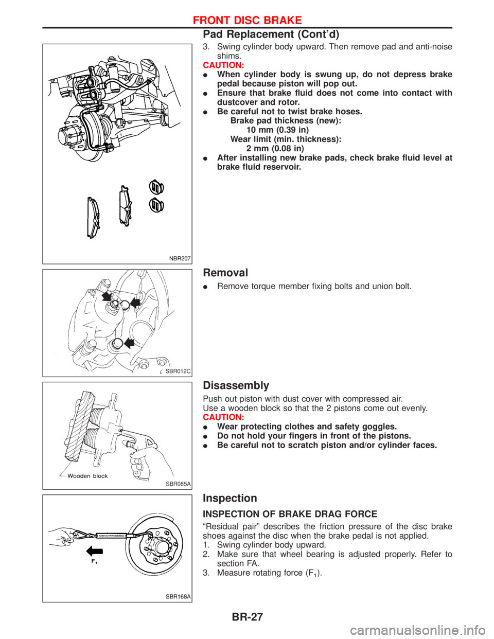
3. Swing cylinder body upward. Then remove pad and anti-noise
shims.
CAUTION:
IWhen cylinder body is swung up, do not depress brake
pedal because piston will pop out.
IEnsure that brake fluid does not come into contact with
dustcover and rotor.
IBe careful not to twist brake hoses.
Brake pad thickness (new):
10 mm (0.39 in)
Wear limit (min. thickness):
2 mm (0.08 in)
IAfter installing new brake pads, check brake fluid level at
brake fluid reservoir.
Removal
IRemove torque member fixing bolts and union bolt.
Disassembly
Push out piston with dust cover with compressed air.
Use a wooden block so that the 2 pistons come out evenly.
CAUTION:
IWear protecting clothes and safety goggles.
IDo not hold your fingers in front of the pistons.
IBe careful not to scratch piston and/or cylinder faces.
Inspection
INSPECTION OF BRAKE DRAG FORCE
ªResidual pairº describes the friction pressure of the disc brake
shoes against the disc when the brake pedal is not applied.
1. Swing cylinder body upward.
2. Make sure that wheel bearing is adjusted properly. Refer to
section FA.
3. Measure rotating force (F
1).
NBR207
SBR012C
SBR085A
SBR168A
FRONT DISC BRAKE
Pad Replacement (Cont'd)
BR-27
Page 1263 of 1767
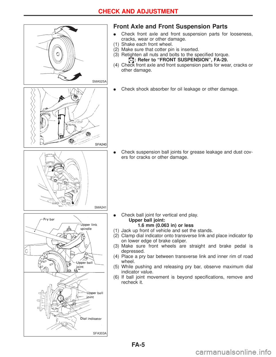
Front Axle and Front Suspension Parts
ICheck front axle and front suspension parts for looseness,
cracks, wear or other damage.
(1) Shake each front wheel.
(2) Make sure that cotter pin is inserted.
(3) Retighten all nuts and bolts to the specified torque.
: Refer to ªFRONT SUSPENSIONº, FA-29.
(4) Check front axle and front suspension parts for wear, cracks or
other damage.
ICheck shock absorber for oil leakage or other damage.
ICheck suspension ball joints for grease leakage and dust cov-
ers for cracks or other damage.
ICheck ball joint for vertical end play.
Upper ball joint:
1.6 mm (0.063 in) or less
(1) Jack up front of vehicle and set the stands.
(2) Clamp dial indicator onto transverse link and place indicator tip
on lower edge of brake caliper.
(3) Make sure front wheels are straight and brake pedal is
depressed.
(4) Place a pry bar between transverse link and inner rim of road
wheel.
(5) While pushing and releasing pry bar, observe maximum dial
indicator value.
(6) If ball joint movement is beyond specifications, remove and
recheck it.
SMA525A
SFA240
SMA241
SFA303A
CHECK AND ADJUSTMENT
FA-5
Page 1265 of 1767
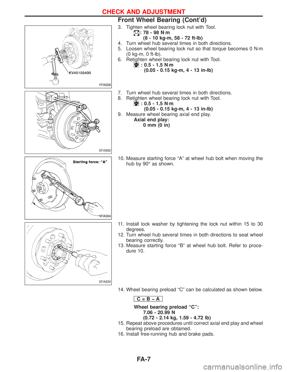
3. Tighten wheel bearing lock nut with Tool.
:78-98N×m
(8 - 10 kg-m, 58 - 72 ft-lb)
4. Turn wheel hub several times in both directions.
5. Loosen wheel bearing lock nut so that torque becomes 0 N×m
(0 kg-m, 0 ft-lb).
6. Retighten wheel bearing lock nut with Tool.
: 0.5 - 1.5 N×m
(0.05 - 0.15 kg-m,4-13in-lb)
7. Turn wheel hub several times in both directions.
8. Retighten wheel bearing lock nut with Tool.
: 0.5 - 1.5 N×m
(0.05 - 0.15 kg-m,4-13in-lb)
9. Measure wheel bearing axial end play.
Axial end play:
0mm(0in)
10. Measure starting force ªAº at wheel hub bolt when moving the
hub by 90É as shown.
11. Install lock washer by tightening the lock nut within 15 to 30
degrees.
12. Turn wheel hub several times in both directions to seat wheel
bearing correctly.
13. Measure starting force ªBº at wheel hub bolt. Refer to proce-
dure 10.
14. Wheel bearing preload ªCº can be calculated as shown below.
C=BþA
Wheel bearing preload ªCº:
7.06 - 20.99 N
(0.72 - 2.14 kg, 1.59 - 4.72 lb)
15. Repeat above procedures until correct axial end play and wheel
bearing preload are obtained.
16. Install free-running hub and brake pads.
YFA009
SFA892
YFA004
SFA830
CHECK AND ADJUSTMENT
Front Wheel Bearing (Cont'd)
FA-7
Page 1269 of 1767
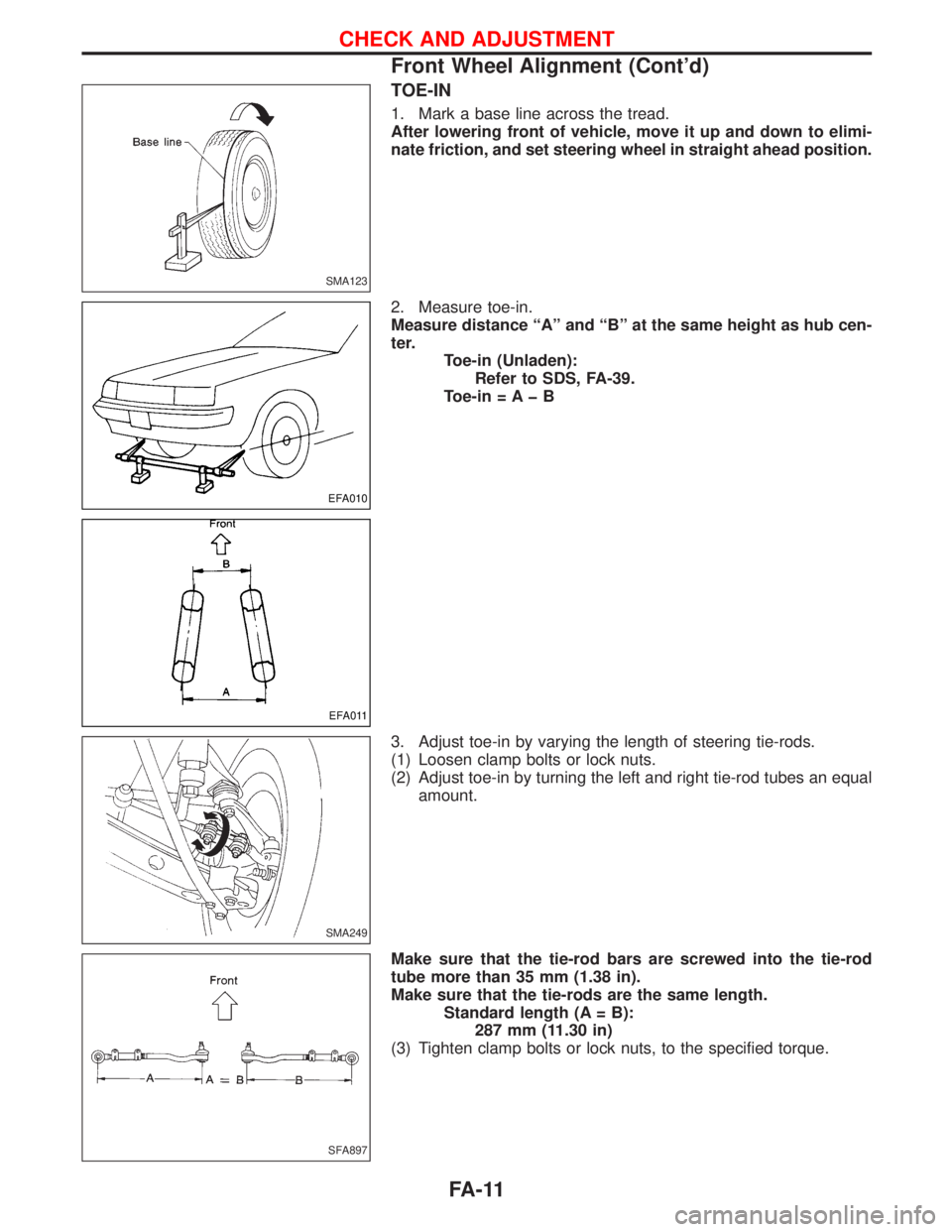
TOE-IN
1. Mark a base line across the tread.
After lowering front of vehicle, move it up and down to elimi-
nate friction, and set steering wheel in straight ahead position.
2. Measure toe-in.
Measure distance ªAº and ªBº at the same height as hub cen-
ter.
Toe-in (Unladen):
Refer to SDS, FA-39.
Toe-in = A þ B
3. Adjust toe-in by varying the length of steering tie-rods.
(1) Loosen clamp bolts or lock nuts.
(2) Adjust toe-in by turning the left and right tie-rod tubes an equal
amount.
Make sure that the tie-rod bars are screwed into the tie-rod
tube more than 35 mm (1.38 in).
Make sure that the tie-rods are the same length.
Standard length (A = B):
287 mm (11.30 in)
(3) Tighten clamp bolts or lock nuts, to the specified torque.
SMA123
EFA010
EFA011
SMA249
SFA897
CHECK AND ADJUSTMENT
Front Wheel Alignment (Cont'd)
FA-11
Page 1297 of 1767
Inspection and Adjustment
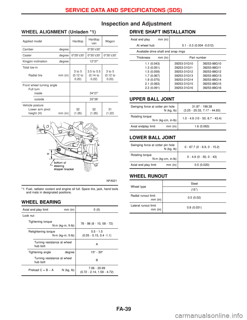
WHEEL ALIGNMENT (Unladen *1)
Applied model HardtopHardtop
vanWagon
Camber degree 0É30¢ 30¢
Caster degree 0É29¢ 30¢0É30¢ 30¢0É30¢ 30¢
Kingpin inclination degree 12É37¢
Total toe-in
Radial tire mm (in)3to5
(0.12 to
0.20)3.5 to 5.5
(0.14 to
0.22)3to5
(0.12 to
0.20)
Front wheel turning angle
Full turn
inside 34É27¢
outside 33É38¢
Vehicle posture
Lower arm pivot
height (H) mm (in)32
(1.26)32
(1.26)31
(1.22)
NFA021
*1: Fuel, radiator coolant and engine oil full. Spare tire, jack, hand tools
and mats in designated positions.
WHEEL BEARING
Axial end play limit mm (in) 0 (0)
Lock nut
Tightening torque
N×m (kg-m, ft-lb)78-98(8-10,58-72)
Retightening torque
N×m (kg-m, ft-lb)0.5 - 1.5
(0.05 - 0.15, 0.4 -1.1)
Turning resistance at wheel
hub boltA
Tightening angle degree 15É - 30É
Turning resistance at wheel
hub boltB
PreloadC=BþA N(kg, lb)7.06 - 20.99
(0.72 - 2.14, 1.59 - 4.72)
DRIVE SHAFT INSTALLATION
Axial end play mm (in)
At wheel hub 0.1 - 0.3 (0.004 -0.012)
Available drive shaft end snap rings
Thickness mm (in) Part number
1.1 (0.043) 39253-31G10 39253-88G10
1.3 (0.051) 39253-31G11 39253-88G11
1.5 (0.059) 39253-31G12 39253-88G12
1.7 (0.067) 39253-31G13 39253-88G13
1.9 (0.075) 39253-31G14 39253-88G14
2.1 (0.083) 39253-31G15 39253-88G15
2.3 (0.091) 39253-31G16 39253-88G16
UPPER BALL JOINT
Swinging force at cotter pin hole
N (kg, lb)31.87 - 199.38
(3.25 - 20.33, 7.17 - 44.83)
Rotating torque
N×m (kg-cm, in-lb)1.0 - 4.9 (10 - 50, 8.7 - 43.4)
Axial endplay limit mm (in) 1.6 (0.063)
LOWER BALL JOINT
Swinging force at cotter pin hole
N (kg, lb)0 - 67.7 (0 - 6.9, 0 - 15.2)
Rotating torque
N×m (kg-cm, in-lb)0 - 4.9 (0 - 50, 0 - 43)
Axial end play limit mm (in) 0.5 (0.020)
WHEEL RUNOUT
Wheel typeSteel
(15²)
Radial runout limit
mm (in)0.5 (0.02)
Lateral runout limit
mm (in)0.8 (0.031)
SERVICE DATA AND SPECIFICATIONS (SDS)
FA-39
Page 1316 of 1767
GENERAL INFORMATION
SECTION
GI
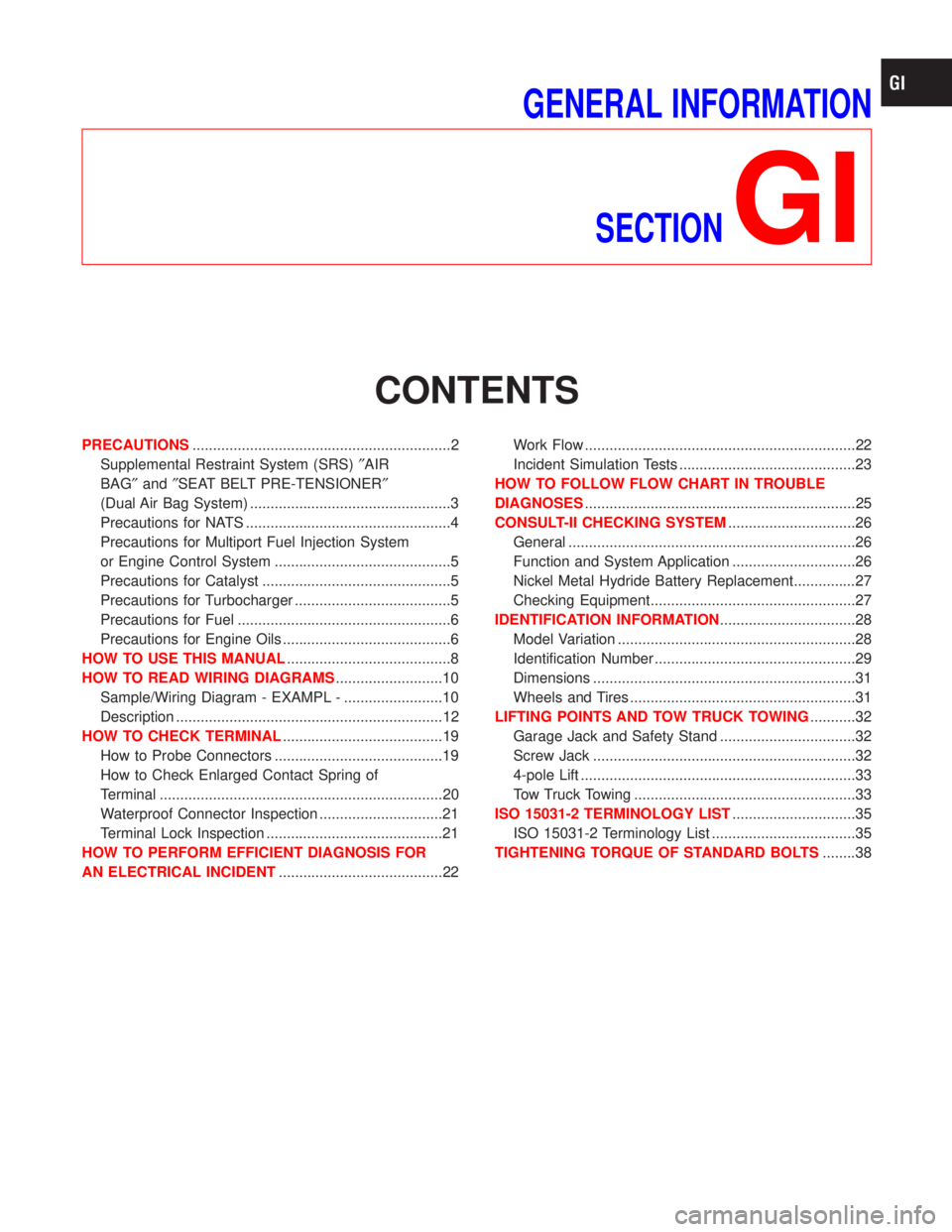
CONTENTS
PRECAUTIONS...............................................................2
Supplemental Restraint System (SRS)²AIR
BAG²and²SEAT BELT PRE-TENSIONER²
(Dual Air Bag System) .................................................3
Precautions for NATS ..................................................4
Precautions for Multiport Fuel Injection System
or Engine Control System ...........................................5
Precautions for Catalyst ..............................................5
Precautions for Turbocharger ......................................5
Precautions for Fuel ....................................................6
Precautions for Engine Oils .........................................6
HOW TO USE THIS MANUAL........................................8
HOW TO READ WIRING DIAGRAMS..........................10
Sample/Wiring Diagram - EXAMPL - ........................10
Description .................................................................12
HOW TO CHECK TERMINAL.......................................19
How to Probe Connectors .........................................19
How to Check Enlarged Contact Spring of
Terminal .....................................................................20
Waterproof Connector Inspection ..............................21
Terminal Lock Inspection ...........................................21
HOW TO PERFORM EFFICIENT DIAGNOSIS FOR
AN ELECTRICAL INCIDENT........................................22Work Flow ..................................................................22
Incident Simulation Tests ...........................................23
HOW TO FOLLOW FLOW CHART IN TROUBLE
DIAGNOSES..................................................................25
CONSULT-II CHECKING SYSTEM...............................26
General ......................................................................26
Function and System Application ..............................26
Nickel Metal Hydride Battery Replacement...............27
Checking Equipment..................................................27
IDENTIFICATION INFORMATION.................................28
Model Variation ..........................................................28
Identification Number .................................................29
Dimensions ................................................................31
Wheels and Tires .......................................................31
LIFTING POINTS AND TOW TRUCK TOWING...........32
Garage Jack and Safety Stand .................................32
Screw Jack ................................................................32
4-pole Lift ...................................................................33
Tow Truck Towing ......................................................33
ISO 15031-2 TERMINOLOGY LIST..............................35
ISO 15031-2 Terminology List ...................................35
TIGHTENING TORQUE OF STANDARD BOLTS........38
Page 1424 of 1767
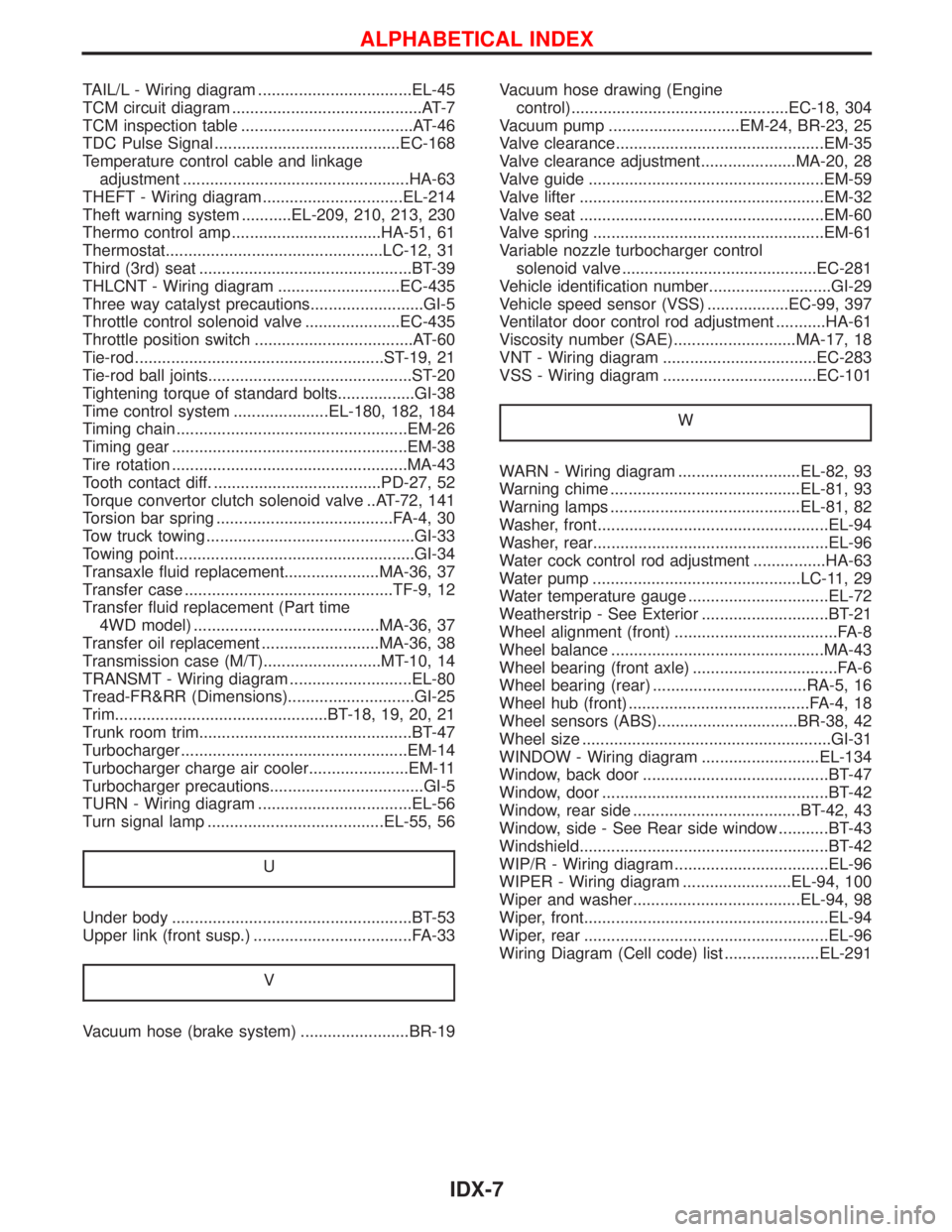
TAIL/L - Wiring diagram ..................................EL-45
TCM circuit diagram ..........................................AT-7
TCM inspection table ......................................AT-46
TDC Pulse Signal .........................................EC-168
Temperature control cable and linkage
adjustment ..................................................HA-63
THEFT - Wiring diagram...............................EL-214
Theft warning system ...........EL-209, 210, 213, 230
Thermo control amp .................................HA-51, 61
Thermostat................................................LC-12, 31
Third (3rd) seat ...............................................BT-39
THLCNT - Wiring diagram ...........................EC-435
Three way catalyst precautions.........................GI-5
Throttle control solenoid valve .....................EC-435
Throttle position switch ...................................AT-60
Tie-rod .......................................................ST-19, 21
Tie-rod ball joints.............................................ST-20
Tightening torque of standard bolts.................GI-38
Time control system .....................EL-180, 182, 184
Timing chain ...................................................EM-26
Timing gear ....................................................EM-38
Tire rotation ....................................................MA-43
Tooth contact diff. .....................................PD-27, 52
Torque convertor clutch solenoid valve ..AT-72, 141
Torsion bar spring .......................................FA-4, 30
Tow truck towing ..............................................GI-33
Towing point.....................................................GI-34
Transaxle fluid replacement.....................MA-36, 37
Transfer case ..............................................TF-9, 12
Transfer fluid replacement (Part time
4WD model) .........................................MA-36, 37
Transfer oil replacement ..........................MA-36, 38
Transmission case (M/T)..........................MT-10, 14
TRANSMT - Wiring diagram ...........................EL-80
Tread-FR&RR (Dimensions)............................GI-25
Trim...............................................BT-18, 19, 20, 21
Trunk room trim...............................................BT-47
Turbocharger ..................................................EM-14
Turbocharger charge air cooler......................EM-11
Turbocharger precautions..................................GI-5
TURN - Wiring diagram ..................................EL-56
Turn signal lamp .......................................EL-55, 56
U
Under body .....................................................BT-53
Upper link (front susp.) ...................................FA-33
V
Vacuum hose (brake system) ........................BR-19Vacuum hose drawing (Engine
control)................................................EC-18, 304
Vacuum pump .............................EM-24, BR-23, 25
Valve clearance..............................................EM-35
Valve clearance adjustment.....................MA-20, 28
Valve guide ....................................................EM-59
Valve lifter ......................................................EM-32
Valve seat ......................................................EM-60
Valve spring ...................................................EM-61
Variable nozzle turbocharger control
solenoid valve ...........................................EC-281
Vehicle identification number...........................GI-29
Vehicle speed sensor (VSS) ..................EC-99, 397
Ventilator door control rod adjustment ...........HA-61
Viscosity number (SAE)...........................MA-17, 18
VNT - Wiring diagram ..................................EC-283
VSS - Wiring diagram ..................................EC-101
W
WARN - Wiring diagram ...........................EL-82, 93
Warning chime ..........................................EL-81, 93
Warning lamps ..........................................EL-81, 82
Washer, front ...................................................EL-94
Washer, rear....................................................EL-96
Water cock control rod adjustment ................HA-63
Water pump ..............................................LC-11, 29
Water temperature gauge ...............................EL-72
Weatherstrip - See Exterior ............................BT-21
Wheel alignment (front) ....................................FA-8
Wheel balance ...............................................MA-43
Wheel bearing (front axle) ................................FA-6
Wheel bearing (rear) ..................................RA-5, 16
Wheel hub (front) ........................................FA-4, 18
Wheel sensors (ABS)...............................BR-38, 42
Wheel size .......................................................GI-31
WINDOW - Wiring diagram ..........................EL-134
Window, back door .........................................BT-47
Window, door ..................................................BT-42
Window, rear side .....................................BT-42, 43
Window, side - See Rear side window ...........BT-43
Windshield.......................................................BT-42
WIP/R - Wiring diagram ..................................EL-96
WIPER - Wiring diagram ........................EL-94, 100
Wiper and washer.....................................EL-94, 98
Wiper, front......................................................EL-94
Wiper, rear ......................................................EL-96
Wiring Diagram (Cell code) list .....................EL-291
ALPHABETICAL INDEX
IDX-7
Page 1460 of 1767
MAINTENANCE
SECTION
MA
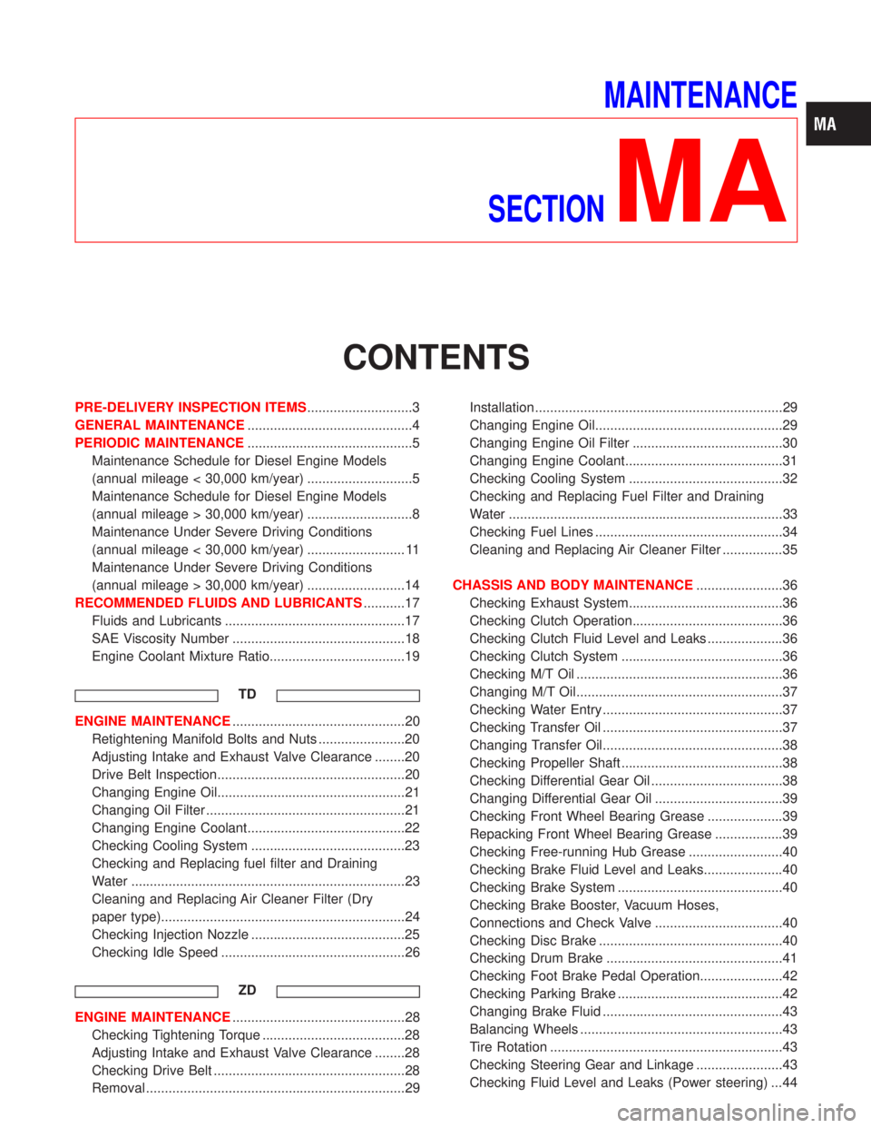
CONTENTS
PRE-DELIVERY INSPECTION ITEMS............................3
GENERAL MAINTENANCE............................................4
PERIODIC MAINTENANCE............................................5
Maintenance Schedule for Diesel Engine Models
(annual mileage < 30,000 km/year) ............................5
Maintenance Schedule for Diesel Engine Models
(annual mileage > 30,000 km/year) ............................8
Maintenance Under Severe Driving Conditions
(annual mileage < 30,000 km/year) .......................... 11
Maintenance Under Severe Driving Conditions
(annual mileage > 30,000 km/year) ..........................14
RECOMMENDED FLUIDS AND LUBRICANTS...........17
Fluids and Lubricants ................................................17
SAE Viscosity Number ..............................................18
Engine Coolant Mixture Ratio....................................19
TD
ENGINE MAINTENANCE..............................................20
Retightening Manifold Bolts and Nuts .......................20
Adjusting Intake and Exhaust Valve Clearance ........20
Drive Belt Inspection..................................................20
Changing Engine Oil..................................................21
Changing Oil Filter .....................................................21
Changing Engine Coolant..........................................22
Checking Cooling System .........................................23
Checking and Replacing fuel filter and Draining
Water .........................................................................23
Cleaning and Replacing Air Cleaner Filter (Dry
paper type).................................................................24
Checking Injection Nozzle .........................................25
Checking Idle Speed .................................................26
ZD
ENGINE MAINTENANCE..............................................28
Checking Tightening Torque ......................................28
Adjusting Intake and Exhaust Valve Clearance ........28
Checking Drive Belt ...................................................28
Removal .....................................................................29Installation ..................................................................29
Changing Engine Oil..................................................29
Changing Engine Oil Filter ........................................30
Changing Engine Coolant..........................................31
Checking Cooling System .........................................32
Checking and Replacing Fuel Filter and Draining
Water .........................................................................33
Checking Fuel Lines ..................................................34
Cleaning and Replacing Air Cleaner Filter ................35
CHASSIS AND BODY MAINTENANCE.......................36
Checking Exhaust System.........................................36
Checking Clutch Operation........................................36
Checking Clutch Fluid Level and Leaks ....................36
Checking Clutch System ...........................................36
Checking M/T Oil .......................................................36
Changing M/T Oil.......................................................37
Checking Water Entry ................................................37
Checking Transfer Oil ................................................37
Changing Transfer Oil................................................38
Checking Propeller Shaft ...........................................38
Checking Differential Gear Oil ...................................38
Changing Differential Gear Oil ..................................39
Checking Front Wheel Bearing Grease ....................39
Repacking Front Wheel Bearing Grease ..................39
Checking Free-running Hub Grease .........................40
Checking Brake Fluid Level and Leaks.....................40
Checking Brake System ............................................40
Checking Brake Booster, Vacuum Hoses,
Connections and Check Valve ..................................40
Checking Disc Brake .................................................40
Checking Drum Brake ...............................................41
Checking Foot Brake Pedal Operation......................42
Checking Parking Brake ............................................42
Changing Brake Fluid ................................................43
Balancing Wheels ......................................................43
Tire Rotation ..............................................................43
Checking Steering Gear and Linkage .......................43
Checking Fluid Level and Leaks (Power steering) ...44