Page 444 of 1767
DIAGNOSTIC PROCEDURE
1 INSPECTION START
Start engine.
Is engine running?
YesorNo
Ye sEGO TO 14.
NoEGO TO 2.
2 CHECK ECM POWER SUPPLY CIRCUIT-I
1. Turn ignition switch ªONº.
2. Check voltage between ECM terminal 38 and ground with CONSULT-II or tester.
SEF397Y
OK or NG
OKEGO TO 4.
NGEGO TO 3.
3 DETECT MALFUNCTIONING PART
Check the following.
I10A fuse
IHarness for open or short between ECM and fuse
ERepair open circuit or short to ground or short to power in harness or connectors.
4 CHECK ECM GROUND CIRCUIT FOR OPEN AND SHORT
1. Turn ignition switch ªOFFº.
2. Disconnect ECM harness connector.
3. Check harness continuity between ECM terminals 39, 43, 106, 112, 118 and engine ground. Refer to Wiring Diagram.
Continuity should exist.
4. Also check harness for short to ground and short to power.
OK or NG
OKEGO TO 6.
NGEGO TO 5.
TROUBLE DIAGNOSIS FOR POWER SUPPLYZD30DDTi
Main Power Supply and Ground Circuit
(Cont'd)
EC-82
Page 446 of 1767
7 CHECK ECM POWER SUPPLY CIRCUIT-III
1. Disconnect ECM relay.
MEC021E
2. Check voltage between relay terminals 2, 3 and ground with CONSULT-II or tester.
MEC978DVoltage: Battery Voltage
OK or NG
OKEGO TO 9.
NGEGO TO 8.
8 DETECT MALFUNCTIONING PART
Check the following.
I10A fuse
I15A fuse
IHarness for open or short between ECM relay and battery
ERepair open circuit or short to ground or short to power in harness or connectors.
9 CHECK OUTPUT SIGNAL CIRCUIT FOR OPEN AND SHORT
1. Disconnect ECM harness connector.
2. Check harness continuity between ECM terminal 4 and ECM relay terminal 1. Refer to Wiring Diagram.
Continuity should exist.
3. Also check harness for short to ground and short to power.
OK or NG
OKEGO TO 11.
NGEGO TO 10.
TROUBLE DIAGNOSIS FOR POWER SUPPLYZD30DDTi
Main Power Supply and Ground Circuit
(Cont'd)
EC-84
Page 448 of 1767
14 CHECK ECM POWER SUPPLY CIRCUIT-V
1. Reconnect all harness connectors disconnected.
2. Turn ignition switch ªONº.
3. Check voltage between ECM terminal 102 and ground with CONSULT-II or tester.
SEF290Z
OK or NG
OKEGO TO 16.
NGEGO TO 15.
15 DETECT MALFUNCTIONING PART
Check the following.
I10A fuse
IHarness for open or short between ECM and fuse
ERepair open circuit or short to ground or short to power in harness or connectors.
16 CHECK ECM POWER SUPPLY CIRCUIT-VI
1. Turn ignition switch ªOFFº.
2. Disconnect ECM relay.
MEC021E
3. Disconnect ECM harness connector.
4. Check harness continuity between ECM terminals 56, 61, 116 and ECM relay terminal 5. Refer to Wiring Diagram.
Continuity should exist.
5. Also check harness for short to ground and short to power.
OK or NG
OKEGO TO 18.
NGEGO TO 17.
TROUBLE DIAGNOSIS FOR POWER SUPPLYZD30DDTi
Main Power Supply and Ground Circuit
(Cont'd)
EC-86
Page 569 of 1767
3 DETECT MALFUNCTIONING PART
Check the following.
IFuse block (J/B) connector F114 (LHD models), M835 (RHD models)
I15A fuse
IHarness for open and short between stop lamp switch and fuse
ERepair open circuit or short to ground or short to power in harness or connectors.
4 CHECK STOP LAMP SWITCH INPUT SIGNAL CIRCUIT FOR OPEN AND SHORT
1. Turn ignition switch ªOFFº.
2. Disconnect ECM harness connector.
3. Disconnect stop lamp switch harness connector.
MEC027E
4. Check harness continuity between ECM terminal 17 and stop lamp switch terminal 2. Refer to Wiring Diagram.
Continuity should exist.
5. Also check harness for short to ground and short to power.
OK or NG
OKEGO TO 5.
NGERepair open circuit or short to ground or short to power in harness or connectors.
DTC 0807 ECM 14ZD30DDTi
Diagnostic Procedure (Cont'd)
EC-207
Page 573 of 1767
Diagnostic Procedure
1 CHECK ECM POWER SUPPLY CIRCUIT
1. Turn ignition switch ªOFFº.
2. Disconnect ECM relay.
MEC021E
3. Check voltage between ECM relay terminals 2, 3 and ground with CONSULT-II or tester.
MEC978DVoltage: Battery voltage
OK or NG
OKEGO TO 3.
NGEGO TO 2.
2 DETECT MALFUNCTIONING PART
Check the following.
1. 10A fuse
2. 15A fuse
3. Harness for open and short between ECM relay and battery
ERepair open circuit or short to ground or short to power in harness or connectors.
3 CHECK ECM INPUT SIGNAL CIRCUIT FOR OPEN AND SHORT
1. Turn ignition switch ªOFFº.
2. Disconnect ECM harness connector.
3. Check harness continuity between ECM terminals 56, 61, 116 and ECM relay terminal 5. Refer to Wiring Diagram.
Continuity should exist.
4. Also check harness for short to ground and short to power.
OK or NG
OKEGO TO 5.
NGEGO TO 4.
DTC 0902 ECM RLYZD30DDTi
EC-211
Page 606 of 1767

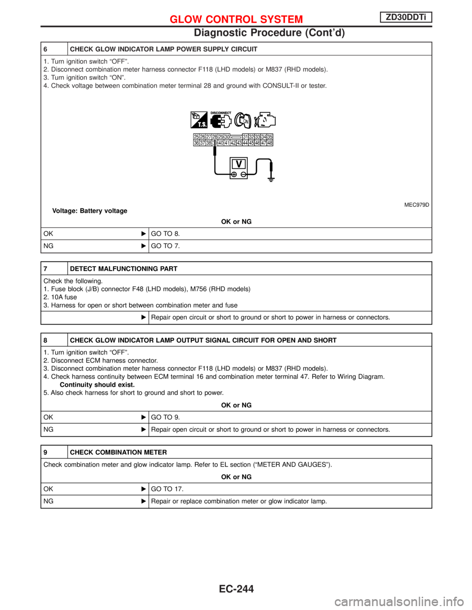
6 CHECK GLOW INDICATOR LAMP POWER SUPPLY CIRCUIT
1. Turn ignition switch ªOFFº.
2. Disconnect combination meter harness connector F118 (LHD models) or M837 (RHD models).
3. Turn ignition switch ªONº.
4. Check voltage between combination meter terminal 28 and ground with CONSULT-II or tester.
MEC979DVoltage: Battery voltage
OK or NG
OKEGO TO 8.
NGEGO TO 7.
7 DETECT MALFUNCTIONING PART
Check the following.
1. Fuse block (J/B) connector F48 (LHD models), M756 (RHD models)
2. 10A fuse
3. Harness for open or short between combination meter and fuse
ERepair open circuit or short to ground or short to power in harness or connectors.
8 CHECK GLOW INDICATOR LAMP OUTPUT SIGNAL CIRCUIT FOR OPEN AND SHORT
1. Turn ignition switch ªOFFº.
2. Disconnect ECM harness connector.
3. Disconnect combination meter harness connector F118 (LHD models) or M837 (RHD models).
4. Check harness continuity between ECM terminal 16 and combination meter terminal 47. Refer to Wiring Diagram.
Continuity should exist.
5. Also check harness for short to ground and short to power.
OK or NG
OKEGO TO 9.
NGERepair open circuit or short to ground or short to power in harness or connectors.
9 CHECK COMBINATION METER
Check combination meter and glow indicator lamp. Refer to EL section (ªMETER AND GAUGESº).
OK or NG
OKEGO TO 17.
NGERepair or replace combination meter or glow indicator lamp.
GLOW CONTROL SYSTEMZD30DDTi
Diagnostic Procedure (Cont'd)
EC-244
Page 607 of 1767
10 CHECK GLOW RELAY POWER SUPPLY CIRCUIT
1. Turn ignition switch ªOFFº.
2. Disconnect glow relay.
MEC004E
3. Check voltage between glow relay terminals 2, 5 and ground with CONSULT-II or tester.
MEC980DVoltage: Battery voltage
OK or NG
OKEGO TO 12.
NGEGO TO 11.
11 DETECT MALFUNCTIONING PART
Check the following.
I80A fusible link
I10A fuse
IHarness for open or short between glow relay and battery
ERepair harness or connectors.
12 CHECK GLOW RELAY OUTPUT SIGNAL CIRCUIT FOR OPEN AND SHORT
1. Disconnect ECM harness connector.
2. Check harness continuity between ECM terminal 111 and glow relay terminal 1. Refer to Wiring Diagram.
Continuity should exist.
3. Also check harness for short to ground and short to power.
OK or NG
OKEGO TO 14.
NGEGO TO 13.
GLOW CONTROL SYSTEMZD30DDTi
Diagnostic Procedure (Cont'd)
EC-245
Page 623 of 1767

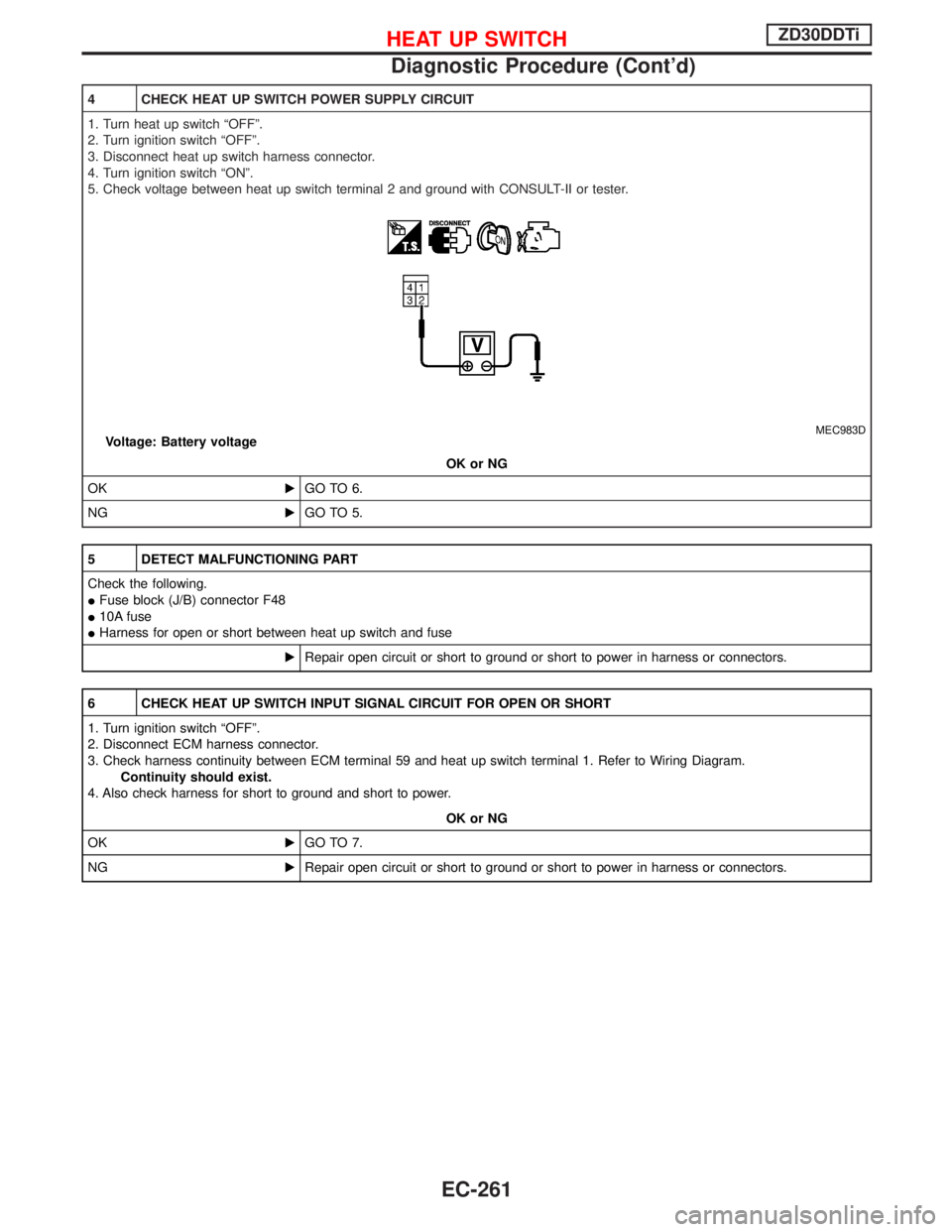
4 CHECK HEAT UP SWITCH POWER SUPPLY CIRCUIT
1. Turn heat up switch ªOFFº.
2. Turn ignition switch ªOFFº.
3. Disconnect heat up switch harness connector.
4. Turn ignition switch ªONº.
5. Check voltage between heat up switch terminal 2 and ground with CONSULT-II or tester.
MEC983DVoltage: Battery voltage
OK or NG
OKEGO TO 6.
NGEGO TO 5.
5 DETECT MALFUNCTIONING PART
Check the following.
IFuse block (J/B) connector F48
I10A fuse
IHarness for open or short between heat up switch and fuse
ERepair open circuit or short to ground or short to power in harness or connectors.
6 CHECK HEAT UP SWITCH INPUT SIGNAL CIRCUIT FOR OPEN OR SHORT
1. Turn ignition switch ªOFFº.
2. Disconnect ECM harness connector.
3. Check harness continuity between ECM terminal 59 and heat up switch terminal 1. Refer to Wiring Diagram.
Continuity should exist.
4. Also check harness for short to ground and short to power.
OK or NG
OKEGO TO 7.
NGERepair open circuit or short to ground or short to power in harness or connectors.
HEAT UP SWITCHZD30DDTi
Diagnostic Procedure (Cont'd)
EC-261