2002 NISSAN TERRANO fuse diagram
[x] Cancel search: fuse diagramPage 1013 of 1767
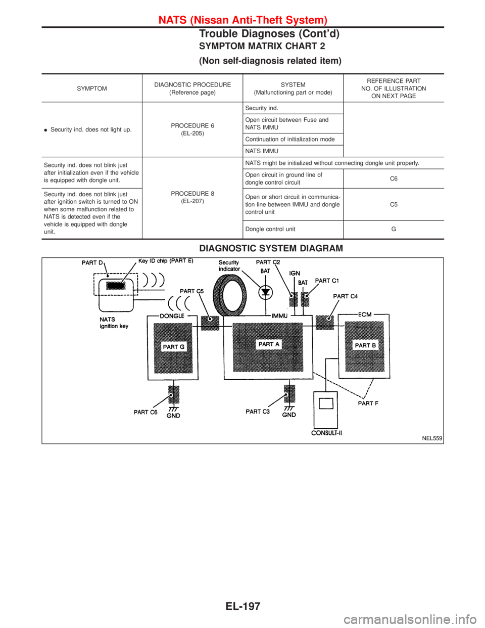
SYMPTOM MATRIX CHART 2
(Non self-diagnosis related item)
SYMPTOMDIAGNOSTIC PROCEDURE
(Reference page)SYSTEM
(Malfunctioning part or mode)REFERENCE PART
NO. OF ILLUSTRATION
ON NEXT PAGE
ISecurity ind. does not light up.PROCEDURE 6
(EL-205)Security ind.
Open circuit between Fuse and
NATS IMMU
Continuation of initialization mode
NATS IMMU
Security ind. does not blink just
after initialization even if the vehicle
is equipped with dongle unit.
PROCEDURE 8
(EL-207)NATS might be initialized without connecting dongle unit properly.
Open circuit in ground line of
dongle control circuitC6
Security ind. does not blink just
after ignition switch is turned to ON
when some malfunction related to
NATS is detected even if the
vehicle is equipped with dongle
unit.Open or short circuit in communica-
tion line between IMMU and dongle
control unitC5
Dongle control unit G
DIAGNOSTIC SYSTEM DIAGRAM
NEL559
NATS (Nissan Anti-Theft System)
Trouble Diagnoses (Cont'd)
EL-197
Page 1327 of 1767
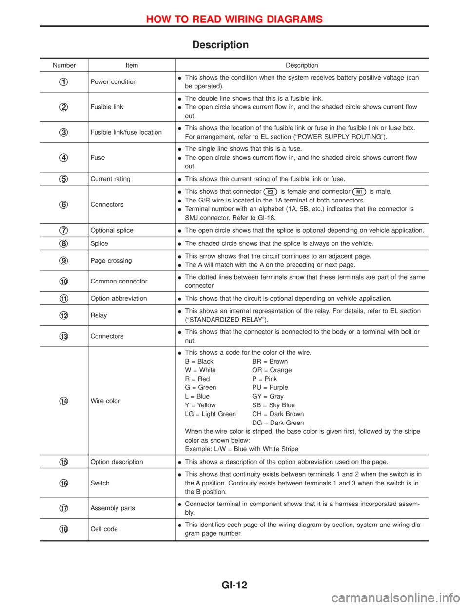
Description
Number Item Description
q1Power conditionIThis shows the condition when the system receives battery positive voltage (can
be operated).
q2Fusible linkIThe double line shows that this is a fusible link.
IThe open circle shows current flow in, and the shaded circle shows current flow
out.
q3Fusible link/fuse locationIThis shows the location of the fusible link or fuse in the fusible link or fuse box.
For arrangement, refer to EL section (ªPOWER SUPPLY ROUTINGº).
q4FuseIThe single line shows that this is a fuse.
IThe open circle shows current flow in, and the shaded circle shows current flow
out.
q5Current ratingIThis shows the current rating of the fusible link or fuse.
q6ConnectorsIThis shows that connector
E3is female and connectorM1is male.
IThe G/R wire is located in the 1A terminal of both connectors.
ITerminal number with an alphabet (1A, 5B, etc.) indicates that the connector is
SMJ connector. Refer to GI-18.
q7Optional spliceIThe open circle shows that the splice is optional depending on vehicle application.
q8SpliceIThe shaded circle shows that the splice is always on the vehicle.
q9Page crossingIThis arrow shows that the circuit continues to an adjacent page.
IThe A will match with the A on the preceding or next page.
q10Common connectorIThe dotted lines between terminals show that these terminals are part of the same
connector.
q11Option abbreviationIThis shows that the circuit is optional depending on vehicle application.
q12RelayIThis shows an internal representation of the relay. For details, refer to EL section
(ªSTANDARDIZED RELAYº).
q13ConnectorsIThis shows that the connector is connected to the body or a terminal with bolt or
nut.
q14Wire colorIThis shows a code for the color of the wire.
B = Black BR = Brown
W = White OR = Orange
R = Red P = Pink
G = Green PU = Purple
L = Blue GY = Gray
Y = Yellow SB = Sky Blue
LG = Light Green CH = Dark Brown
DG = Dark Green
When the wire color is striped, the base color is given first, followed by the stripe
color as shown below:
Example: L/W = Blue with White Stripe
q15Option descriptionIThis shows a description of the option abbreviation used on the page.
q16SwitchIThis shows that continuity exists between terminals 1 and 2 when the switch is in
the A position. Continuity exists between terminals 1 and 3 when the switch is in
the B position.
q17Assembly partsIConnector terminal in component shows that it is a harness incorporated assem-
bly.
q18Cell codeIThis identifies each page of the wiring diagram by section, system and wiring dia-
gram page number.
HOW TO READ WIRING DIAGRAMS
GI-12
Page 1328 of 1767
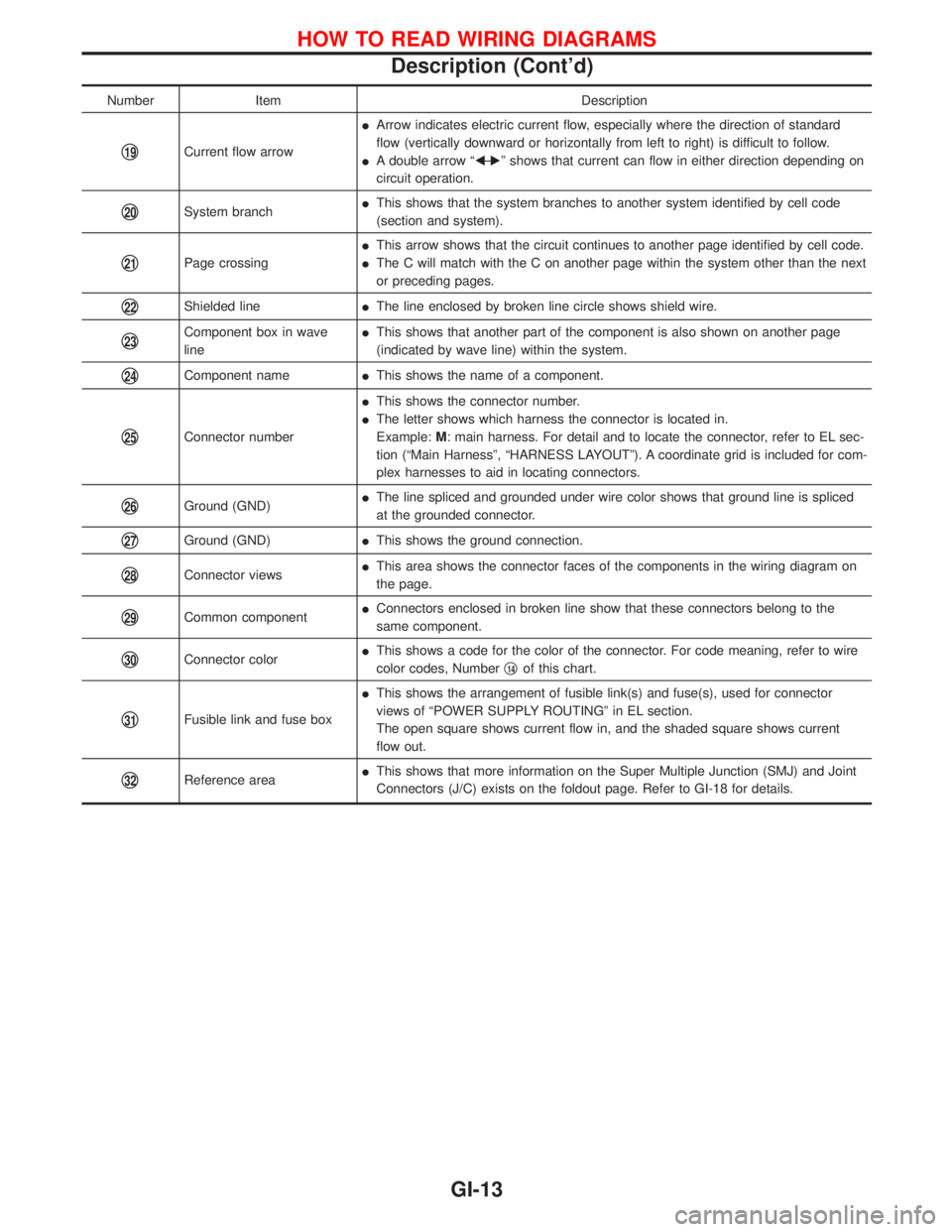
Number Item Description
q19Current flow arrowIArrow indicates electric current flow, especially where the direction of standard
flow (vertically downward or horizontally from left to right) is difficult to follow.
IA double arrow ªFÐ
Eº shows that current can flow in either direction depending on
circuit operation.
q20System branchIThis shows that the system branches to another system identified by cell code
(section and system).
q21Page crossingIThis arrow shows that the circuit continues to another page identified by cell code.
IThe C will match with the C on another page within the system other than the next
or preceding pages.
q22Shielded lineIThe line enclosed by broken line circle shows shield wire.
q23Component box in wave
lineIThis shows that another part of the component is also shown on another page
(indicated by wave line) within the system.
q24Component nameIThis shows the name of a component.
q25Connector numberIThis shows the connector number.
IThe letter shows which harness the connector is located in.
Example:M: main harness. For detail and to locate the connector, refer to EL sec-
tion (ªMain Harnessº, ªHARNESS LAYOUTº). A coordinate grid is included for com-
plex harnesses to aid in locating connectors.
q26Ground (GND)IThe line spliced and grounded under wire color shows that ground line is spliced
at the grounded connector.
q27Ground (GND)IThis shows the ground connection.
q28Connector viewsIThis area shows the connector faces of the components in the wiring diagram on
the page.
q29Common componentIConnectors enclosed in broken line show that these connectors belong to the
same component.
q30Connector colorIThis shows a code for the color of the connector. For code meaning, refer to wire
color codes, Numberq14of this chart.
q31Fusible link and fuse boxIThis shows the arrangement of fusible link(s) and fuse(s), used for connector
views of ªPOWER SUPPLY ROUTINGº in EL section.
The open square shows current flow in, and the shaded square shows current
flow out.
q32Reference areaIThis shows that more information on the Super Multiple Junction (SMJ) and Joint
Connectors (J/C) exists on the foldout page. Refer to GI-18 for details.
HOW TO READ WIRING DIAGRAMS
Description (Cont'd)
GI-13
Page 1405 of 1767
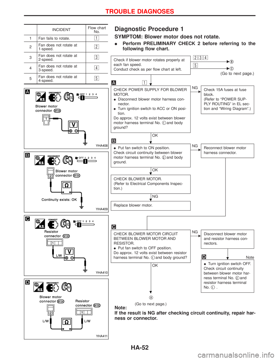
Diagnostic Procedure 1
SYMPTOM: Blower motor does not rotate.
IPerform PRELIMINARY CHECK 2 before referring to the
following flow chart.
Check if blower motor rotates properly at
each fan speed.
Conduct check as per flow chart at left.234EqB5EqC
(Go to next page.)
1
CHECK POWER SUPPLY FOR BLOWER
MOTOR.
IDisconnect blower motor harness con-
nector.
ITurn ignition switch to ACC or ON posi-
tion.
Do approx. 12 volts exist between blower
motor harness terminal No.q
1and body
ground?
OK
ENG
Check 15A fuses at fuse
block.
(Refer to ªPOWER SUP-
PLY ROUTINGº in EL sec-
tion and ªWiring Diagramº.)
IPut fan switch to ON position.
Check circuit continuity between blower
motor harness terminal No.q
2and body
ground.
OK
ENG
Reconnect blower motor
harness connector.
CHECK BLOWER MOTOR.
(Refer to Electrical Components Inspec-
tion.)
NG
Replace blower motor.
CHECK BLOWER MOTOR CIRCUIT
BETWEEN BLOWER MOTOR AND
RESISTOR.
IPut fan switch to OFF position.
Do approx. 12 volts exist between resistor
harness terminal No.q
1and body ground?
OK
ENG
Disconnect blower motor
and resistor harness con-
nectors.
Note
ITurn ignition switch OFF.
Check circuit continuity
between blower motor har-
ness terminal No.q
2and
resistor harness terminal
No.q
1.
qA
(Go to next page.)Note:
If the result is NG after checking circuit continuity, repair har-
ness or connector.
INCIDENTFlow chart
No.
1 Fan fails to rotate.
1
2Fan does not rotate at
1-speed.2
3Fan does not rotate at
2-speed.3
4Fan does not rotate at
3-speed.4
5Fan does not rotate at
4-speed.5
YHA408
YHA409
YHA410
YHA411
H
H
H
H
H
H
TROUBLE DIAGNOSES
HA-52
Page 1408 of 1767
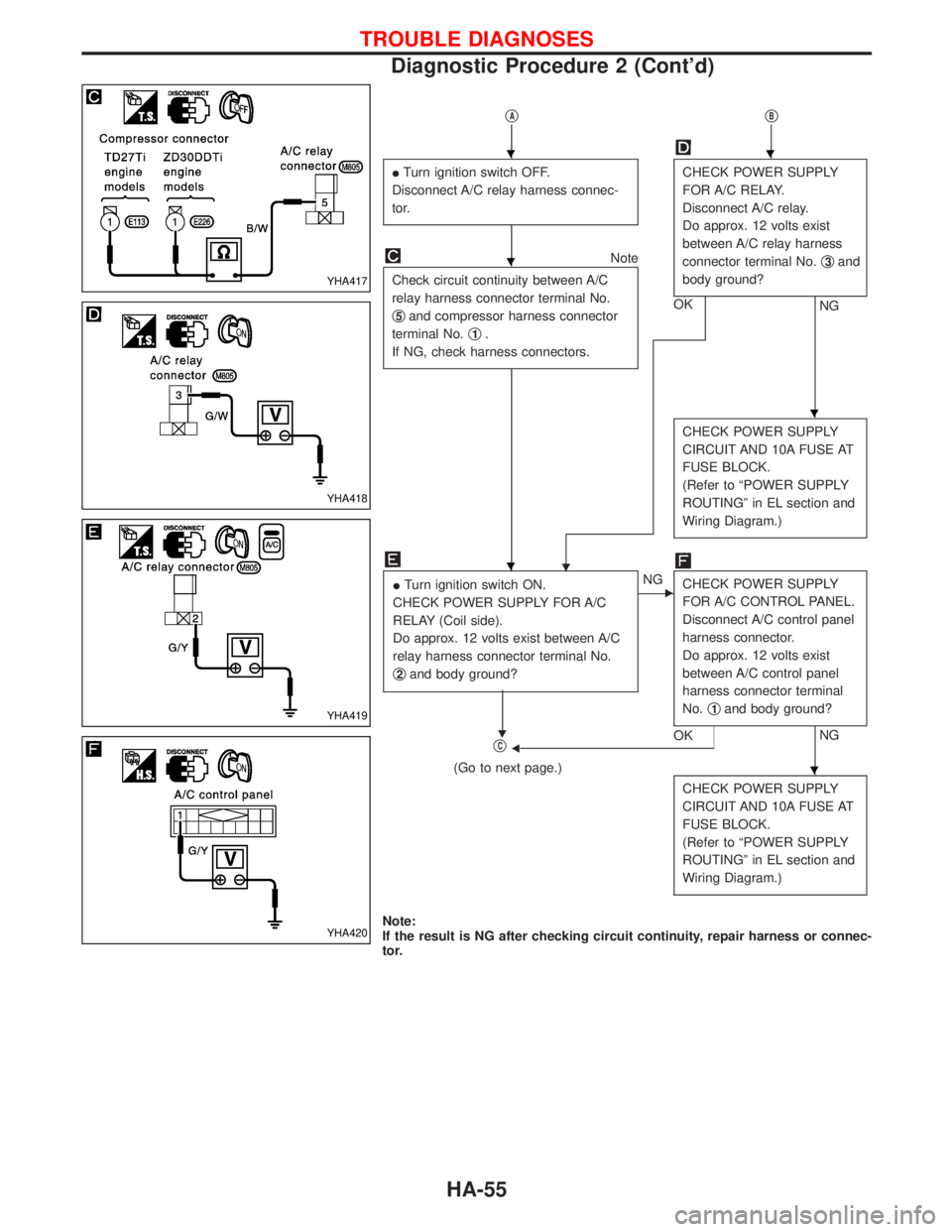
qAqB
ITurn ignition switch OFF.
Disconnect A/C relay harness connec-
tor.CHECK POWER SUPPLY
FOR A/C RELAY.
Disconnect A/C relay.
Do approx. 12 volts exist
between A/C relay harness
connector terminal No.q
3and
body ground?
NG OK
Note
Check circuit continuity between A/C
relay harness connector terminal No.
q
5and compressor harness connector
terminal No.q
1.
If NG, check harness connectors.
H
CHECK POWER SUPPLY
CIRCUIT AND 10A FUSE AT
FUSE BLOCK.
(Refer to ªPOWER SUPPLY
ROUTINGº in EL section and
Wiring Diagram.)
ITurn ignition switch ON.
CHECK POWER SUPPLY FOR A/C
RELAY (Coil side).
Do approx. 12 volts exist between A/C
relay harness connector terminal No.
q
2and body ground?
H
ENG
CHECK POWER SUPPLY
FOR A/C CONTROL PANEL.
Disconnect A/C control panel
harness connector.
Do approx. 12 volts exist
between A/C control panel
harness connector terminal
No.q
1and body ground?
NG
OKFqC
(Go to next page.)
CHECK POWER SUPPLY
CIRCUIT AND 10A FUSE AT
FUSE BLOCK.
(Refer to ªPOWER SUPPLY
ROUTINGº in EL section and
Wiring Diagram.)
Note:
If the result is NG after checking circuit continuity, repair harness or connec-
tor.
YHA417
YHA418
YHA419
YHA420
HH
H
H
H
H
TROUBLE DIAGNOSES
Diagnostic Procedure 2 (Cont'd)
HA-55
Page 1412 of 1767
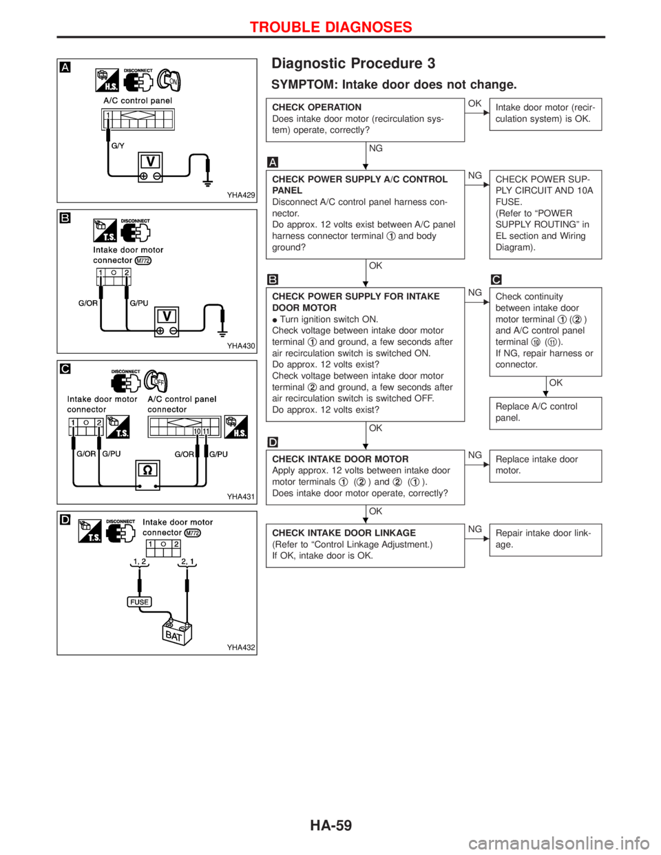
Diagnostic Procedure 3
SYMPTOM: Intake door does not change.
CHECK OPERATION
Does intake door motor (recirculation sys-
tem) operate, correctly?
NG
EOK
Intake door motor (recir-
culation system) is OK.
CHECK POWER SUPPLY A/C CONTROL
PANEL
Disconnect A/C control panel harness con-
nector.
Do approx. 12 volts exist between A/C panel
harness connector terminalq
1and body
ground?
OK
ENG
CHECK POWER SUP-
PLY CIRCUIT AND 10A
FUSE.
(Refer to ªPOWER
SUPPLY ROUTINGº in
EL section and Wiring
Diagram).
CHECK POWER SUPPLY FOR INTAKE
DOOR MOTOR
ITurn ignition switch ON.
Check voltage between intake door motor
terminalq
1and ground, a few seconds after
air recirculation switch is switched ON.
Do approx. 12 volts exist?
Check voltage between intake door motor
terminalq
2and ground, a few seconds after
air recirculation switch is switched OFF.
Do approx. 12 volts exist?
OK
ENG
Check continuity
between intake door
motor terminalq
1(q2)
and A/C control panel
terminalq
10(q11).
If NG, repair harness or
connector.
OK
Replace A/C control
panel.
CHECK INTAKE DOOR MOTOR
Apply approx. 12 volts between intake door
motor terminalsq
1(q2) andq2(q1).
Does intake door motor operate, correctly?
OK
ENG
Replace intake door
motor.
CHECK INTAKE DOOR LINKAGE
(Refer to ªControl Linkage Adjustment.)
If OK, intake door is OK.ENG
Repair intake door link-
age.
YHA429
YHA430
YHA431
YHA432
H
H
H
H
H
TROUBLE DIAGNOSES
HA-59
Page 1421 of 1767
F
Fan switch ......................................................HA-60
F/FOG - Wiring diagram .................................EL-51
Final drive disassembly............................PD-15, 37
Final drive pre-inspection .........................PD-15, 37
Final drive removal and installation ...............PD-15
Finisher, interior - See Trim ............................BT-18
Finisher, rear panel .........................................BT-18
Floor trim .........................................................BT-18
Fluid temperature sensor (A/T) .....................AT-141
Fluids .............................................MA-5, 17, 20, 36
Flywheel (clutch) .......................................CL-11, 12
Flywheel runout..............................................EM-94
Fog lamp, front .........................................EL-51, 53
Fog lamp, rear ................................................EL-54
Fork rod (M/T) ................................................MT-13
Forward clutch...............................................AT-157
Front axle ....................................................FA-4, 13
Front bumper ....................................................BT-6
Front case (Transfer) ..................................TF-9, 23
Front combination lamp removal and
installation .....................................................BT-6
Front disc brake .............................................BR-26
Front door .......................................................BT-10
Front Door Trim...............................................BT-19
Front drive shaft (Transfer) .........................TF-9, 19
Front final drive disassembly (4WD) ..............PD-14
Front final drive removal and installa-
tion (4WD) ............................................PD-12, 13
Front fog lamp ..........................................EL-51, 53
Front passenger air bag .................................RS-17
Front seat ........................................................BT-34
Front seat belt ..................................................RS-4
Front seat belt pre-tensioner ..........................RS-12
Front side air bag ...........................................RS-18
Front suspension ........................................FA-4, 29
Fuel cut control (at no load & high
engine speed) .....................................EC-22, 311
Fuel cut solenoid valve ................................EC-376
Fuel cut system ............................................EC-232
Fuel filler lid.......................................................BT-8
Fuel filter replacement...................MA-5, 20, 23, 33
Fuel gauge..................................FE-3, 6, EL-72, 80
Fuel injection system .............................EC-20, 306
Fuel injection timing feed back (Elec-
tronic Fuel Injection Pump) ......................EC-192
Fuel precautions ................................................GI-6
Fuel pump and gauge ..............................FE-3, 6, 7
Fuel system ..................................................FE-3, 6
Fuel tank .......................................................FE-3, 6
Fuel temperature sensor ......................EC-123, 372
Fuse ................................................................EL-17
Fuse and fusible link box .............................Foldout
Fuse block ....................................................Foldout
Fusible link ......................................................EL-17GGarage jack and safety stand .........................GI-32
Gauges .....................................................EL-70, 71
Gear components (M/T) ........MT-11, 14, 16, 21, 23
Generator - See Alternator .............................SC-27
GLOW - Wiring diagram...............................EC-241
Glow control system.....................EC-239, 311, 389
Glow plug .............................................EC-239, 390
Glow relay ............................................EC-241, 396
Grease .........................................MA-17, 39, 40, 44
Ground distribution..........................................EL-18
H
Harness connector ............................................EL-3
Harness connector inspection .........................GI-19
Harness layout ............EL-247, 248, 264, 276, 278,
286, 287, 288, 289, 290
Hazard warning lamp................................EL-55, 56
Headlamp ......EL-26, 29, 30, 31, 37, 38, 39, 42, 43
Headlamp aiming control .............EL-37, 38, 39, 42
Headlamp washer .........................................EL-100
Headlining - See Roof trim .............................BT-20
Heat up switch..............................................EC-258
Heated seat .......................................BT-36, EL-128
HEATER - Wiring diagram .............................HA-41
HEATUP - Wiring diagram ...........................EC-259
Height (Dimensions) ........................................GI-10
HFC134a (R134a) system precaution .............HA-3
HFC134a (R134a) system service
procedure....................................................HA-15
HFC134a (R134a) system service tools ........HA-11
High clutch ....................................................AT-155
H/LAMP - Wiring diagram ............EL-26, 31, 39, 56
Hood..................................................................BT-6
Hood lock system .............................................BT-6
Horn ..............................................................EL-104
HORN - Wiring diagram................................EL-104
How to erase DTC for OBD system ......EC-33, 321
HSEAT - Wiring diagram...............................EL-128
I
Identification .....................................................HA-2
Identification plate .....................................GI-29, 30
Idle speed...............................................EC-50, 338
Idle speed inspection ...............................MA-20, 26
ILL - Wiring diagram .......................................EL-62
Illumination ................................................EL-61, 62
Injection nozzle ......................................EC-24, 313
Injection nozzle inspection ..................MA-5, 20, 25
Injection timing control valve ........................EC-380
INJPMP - Wiring diagram ...EC-126, 164, 171, 178,
185, 195, 235
Instrument panel .............................................BT-16
INT/L - Wiring diagram....................................EL-66
ALPHABETICAL INDEX
IDX-4