2002 NISSAN TERRANO horn
[x] Cancel search: hornPage 817 of 1767

ELECTRICAL SYSTEM
SECTION
EL
When you read wiring diagrams:
IRead GI section, ªHOW TO READ WIRING DIAGRAMSº.
CONTENTS
HARNESS CONNECTOR................................................3
Description ...................................................................3
STANDARDIZED RELAYS..............................................4
Description ...................................................................4
POWER SUPPLY ROUTING...........................................6
Schematic ....................................................................6
Wiring Diagram - POWER - ........................................8
Fuse ...........................................................................17
Fusible Link................................................................17
Circuit Breaker Inspection .........................................17
GROUND DISTRIBUTION.............................................18
COMBINATION SWITCH...............................................23
Check .........................................................................23
Replacement ..............................................................24
STEERING SWITCH......................................................25
Check .........................................................................25
HEADLAMP - Without Daytime Light System -.........26
Wiring Diagram - H/LAMP -.......................................26
HEADLAMP - Daytime Light System -.......................29
Operation ...................................................................29
Schematic ..................................................................30
Wiring Diagram - DTRL - ...........................................31
HEADLAMP - Headlamp Aiming Control -.................37
Description .................................................................37
Replacing Headlamp Aiming Actuator .......................38
Wiring Diagram - H/AIM - ..........................................39
Trouble Diagnoses.....................................................42
HEADLAMP...................................................................43
Bulb Replacement .....................................................43
Aiming Adjustment .....................................................43
EXTERIOR LAMP..........................................................45
Wiring Diagram - TAIL/L - ..........................................45
Wiring Diagram - STOP/L - .......................................48
Wiring Diagram - BACK/L - .......................................49
Wiring Diagram - F/FOG - .........................................51
Front Fog Lamp Aiming Adjustment ..........................53
Wiring Diagram - R/FOG -.........................................54
Schematic ..................................................................55Wiring Diagram - TURN - ..........................................56
Bulb Specifications ....................................................60
INTERIOR LAMP...........................................................61
Schematic ..................................................................61
Wiring Diagram - ILL - ...............................................62
Wiring Diagram - INT/L - ...........................................66
METER AND GAUGES.................................................70
Combination Meter ....................................................70
Schematic ..................................................................71
Wiring Diagram - METER - .......................................72
Combination Meter Self-Diagnosis ............................76
Components Inspection .............................................78
Trouble Diagnoses.....................................................79
Fuel Tank Gauge Unit Check ....................................80
Thermal Transmitter Check .......................................80
Oil Pressure Switch Check ........................................80
WARNING LAMPS AND CHIME...................................81
Schematic ..................................................................81
Wiring Diagram - WARN - .........................................82
Diode Check ..............................................................92
Wiring Diagram - CHIME - ........................................93
WIPER AND WASHER..................................................94
Wiring Diagram - WIPER - ........................................94
Wiring Diagram - WIP/R -..........................................96
Installation ..................................................................98
Washer Nozzle Adjustment .......................................99
Check Valve ...............................................................99
Wiring Diagram - HLC - ...........................................100
HORN, CIGARETTE LIGHTER AND CLOCK............104
Wiring Diagram - HORN - .......................................104
Wiring Diagram - CIGAR -.......................................105
Wiring Diagram - CLOCK -......................................106
REAR WINDOW DEFOGGER AND DOOR
MIRROR DEFOGGER.................................................107
Wiring Diagram - DEF - ...........................................107
Filament Check ........................................................109
Filament Repair ....................................................... 110
AUDIO.......................................................................... 111
Page 838 of 1767

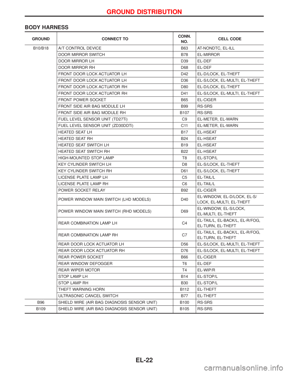
BODY HARNESS
GROUND CONNECT TOCONN.
NO.CELL CODE
B10/B18 A/T CONTROL DEVICE B63 AT-NONDTC, EL-ILL
DOOR MIRROR SWITCH B78 EL-MIRROR
DOOR MIRROR LH D39 EL-DEF
DOOR MIRROR RH D68 EL-DEF
FRONT DOOR LOCK ACTUATOR LH D42 EL-D/LOCK, EL-THEFT
FRONT DOOR LOCK ACTUATOR LH D36 EL-S/LOCK, EL-MULTI, EL-THEFT
FRONT DOOR LOCK ACTUATOR RH D80 EL-D/LOCK, EL-THEFT
FRONT DOOR LOCK ACTUATOR RH D41 EL-S/LOCK, EL-MULTI, EL-THEFT
FRONT POWER SOCKET B65 EL-CIGER
FRONT SIDE AIR BAG MODULE LH B99 RS-SRS
FRONT SIDE AIR BAG MODULE RH B107 RS-SRS
FUEL LEVEL SENSOR UNIT (TD27Ti) C9 EL-METER, EL-WARN
FUEL LEVEL SENSOR UNIT (ZD30DDTi) C11 EL-METER, EL-WARN
HEATED SEAT LH B17 EL-HSEAT
HEATED SEAT RH B24 EL-HSEAT
HEATED SEAT SWITCH LH B19 EL-HSEAT
HEATED SEAT SWITCH RH B22 EL-HSEAT
HIGH-MOUNTED STOP LAMP T8 EL-STOP/L
KEY CYLINDER SWITCH LH D8 EL-S/LOCK, EL-THEFT
KEY CYLINDER SWITCH RH D61 EL-S/LOCK, EL-THEFT
LICENSE PLATE LAMP LH C5 EL-TAIL/L
LICENSE PLATE LAMP RH C6 EL-TAIL/L
POWER SOCKET RELAY B92 EL-CIGER
POWER WINDOW MAIN SWITCH (LHD MODELS) D40EL-WINDOW, EL-D/LOCK, EL-S/
LOCK, EL-MULTI, EL-THEFT
POWER WINDOW MAIN SWITCH (RHD MODELS) D69EL-WINDOW, EL-S/LOCK,
EL-MULTI, EL-THEFT
REAR COMBINATION LAMP LH C4EL-TAIL/L, EL-BACK/L, EL-R/FOG,
EL-TURN, EL-THEFT
REAR COMBINATION LAMP RH C7EL-TAIL/L, EL-BACK/L, EL-R/FOG,
EL-TURN, EL-THEFT
REAR DOOR LOCK ACTUATOR LH D56 EL-S/LOCK, EL-MULTI, EL-THEFT
REAR DOOR LOCK ACTUATOR RH D76 EL-S/LOCK, EL-MULTI, EL-THEFT
REAR POWER SOCKET B66 EL-CIGER
REAR WINDOW DEFOGGER T6 EL-DEF
REAR WIPER MOTOR T4 EL-WIP/R
STOP LAMP LH B14 EL-STOP/L
STOP LAMP RH B30 EL-STOP/L
THEFT WARNING HORN B112 EL-THEFT
ULTRASONIC CANCEL SWITCH B77 EL-THEFT
B96 SHIELD WIRE (AIR BAG DIAGNOSIS SENSOR UNIT) B100 RS-SRS
B109 SHIELD WIRE (AIR BAG DIAGNOSIS SENSOR UNIT) B105 RS-SRS
GROUND DISTRIBUTION
EL-22
Page 920 of 1767

Wiring Diagram Ð HORN Ð
YEL118D
HORN, CIGARETTE LIGHTER AND CLOCK
EL-104
Page 921 of 1767

Wiring Diagram Ð CIGAR Ð
YEL119D
HORN, CIGARETTE LIGHTER AND CLOCK
EL-105
Page 922 of 1767

Wiring Diagram Ð CLOCK Ð
YEL198D
HORN, CIGARETTE LIGHTER AND CLOCK
EL-106
Page 997 of 1767

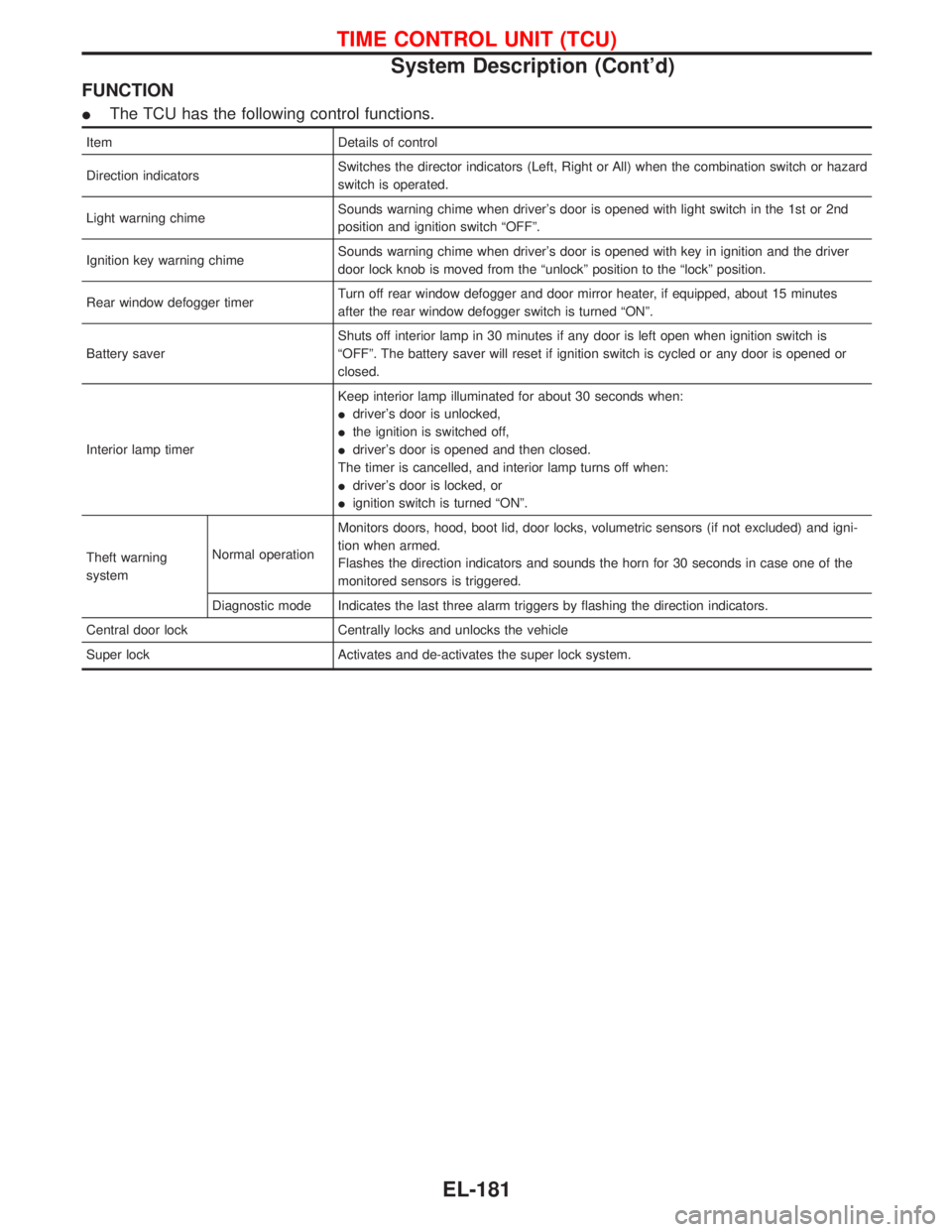
FUNCTION
IThe TCU has the following control functions.
Item Details of control
Direction indicatorsSwitches the director indicators (Left, Right or All) when the combination switch or hazard
switch is operated.
Light warning chimeSounds warning chime when driver's door is opened with light switch in the 1st or 2nd
position and ignition switch ªOFFº.
Ignition key warning chimeSounds warning chime when driver's door is opened with key in ignition and the driver
door lock knob is moved from the ªunlockº position to the ªlockº position.
Rear window defogger timerTurn off rear window defogger and door mirror heater, if equipped, about 15 minutes
after the rear window defogger switch is turned ªONº.
Battery saverShuts off interior lamp in 30 minutes if any door is left open when ignition switch is
ªOFFº. The battery saver will reset if ignition switch is cycled or any door is opened or
closed.
Interior lamp timerKeep interior lamp illuminated for about 30 seconds when:
Idriver's door is unlocked,
Ithe ignition is switched off,
Idriver's door is opened and then closed.
The timer is cancelled, and interior lamp turns off when:
Idriver's door is locked, or
Iignition switch is turned ªONº.
Theft warning
systemNormal operationMonitors doors, hood, boot lid, door locks, volumetric sensors (if not excluded) and igni-
tion when armed.
Flashes the direction indicators and sounds the horn for 30 seconds in case one of the
monitored sensors is triggered.
Diagnostic mode Indicates the last three alarm triggers by flashing the direction indicators.
Central door lock Centrally locks and unlocks the vehicle
Super lock Activates and de-activates the super lock system.
TIME CONTROL UNIT (TCU)
System Description (Cont'd)
EL-181
Page 1027 of 1767

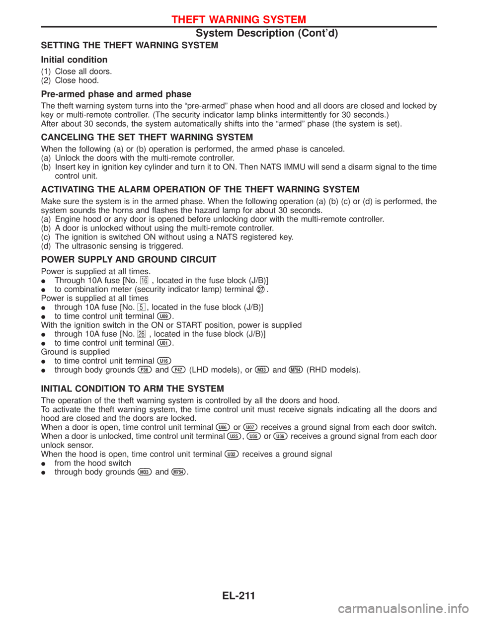
SETTING THE THEFT WARNING SYSTEM
Initial condition
(1) Close all doors.
(2) Close hood.
Pre-armed phase and armed phase
The theft warning system turns into the ªpre-armedº phase when hood and all doors are closed and locked by
key or multi-remote controller. (The security indicator lamp blinks intermittently for 30 seconds.)
After about 30 seconds, the system automatically shifts into the ªarmedº phase (the system is set).
CANCELING THE SET THEFT WARNING SYSTEM
When the following (a) or (b) operation is performed, the armed phase is canceled.
(a) Unlock the doors with the multi-remote controller.
(b) Insert key in ignition key cylinder and turn it to ON. Then NATS IMMU will send a disarm signal to the time
control unit.
ACTIVATING THE ALARM OPERATION OF THE THEFT WARNING SYSTEM
Make sure the system is in the armed phase. When the following operation (a) (b) (c) or (d) is performed, the
system sounds the horns and flashes the hazard lamp for about 30 seconds.
(a) Engine hood or any door is opened before unlocking door with the multi-remote controller.
(b) A door is unlocked without using the multi-remote controller.
(c) The ignition is switched ON without using a NATS registered key.
(d) The ultrasonic sensing is triggered.
POWER SUPPLY AND GROUND CIRCUIT
Power is supplied at all times.
IThrough 10A fuse [No.
16, located in the fuse block (J/B)]
Ito combination meter (security indicator lamp) terminalq
27.
Power is supplied at all times
Ithrough 10A fuse [No.
5, located in the fuse block (J/B)]
Ito time control unit terminal
U09.
With the ignition switch in the ON or START position, power is supplied
Ithrough 10A fuse [No.
26, located in the fuse block (J/B)]
Ito time control unit terminal
U01.
Ground is supplied
Ito time control unit terminal
U16
Ithrough body groundsF36andF47(LHD models), orM33andM754(RHD models).
INITIAL CONDITION TO ARM THE SYSTEM
The operation of the theft warning system is controlled by all the doors and hood.
To activate the theft warning system, the time control unit must receive signals indicating all the doors and
hood are closed and the doors are locked.
When a door is open, time control unit terminal
U06orU07receives a ground signal from each door switch.
When a door is unlocked, time control unit terminal
U25,U35orU36receives a ground signal from each door
unlock sensor.
When the hood is open, time control unit terminal
U32receives a ground signal
Ifrom the hood switch
Ithrough body grounds
M33andM754.
THEFT WARNING SYSTEM
System Description (Cont'd)
EL-211
Page 1028 of 1767

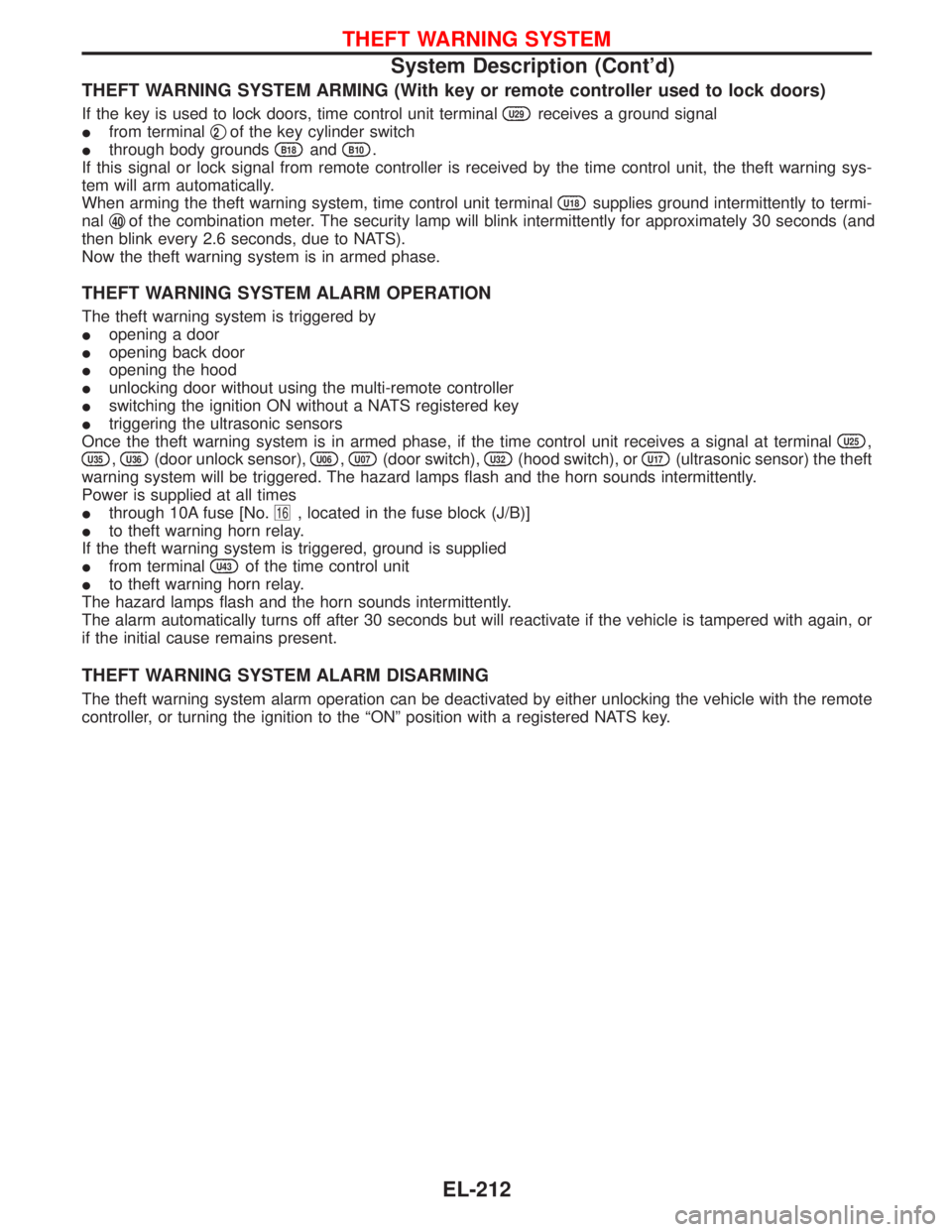
THEFT WARNING SYSTEM ARMING (With key or remote controller used to lock doors)
If the key is used to lock doors, time control unit terminalU29receives a ground signal
Ifrom terminalq
2of the key cylinder switch
Ithrough body grounds
B18andB10.
If this signal or lock signal from remote controller is received by the time control unit, the theft warning sys-
tem will arm automatically.
When arming the theft warning system, time control unit terminal
U18supplies ground intermittently to termi-
nalq
40of the combination meter. The security lamp will blink intermittently for approximately 30 seconds (and
then blink every 2.6 seconds, due to NATS).
Now the theft warning system is in armed phase.
THEFT WARNING SYSTEM ALARM OPERATION
The theft warning system is triggered by
Iopening a door
Iopening back door
Iopening the hood
Iunlocking door without using the multi-remote controller
Iswitching the ignition ON without a NATS registered key
Itriggering the ultrasonic sensors
Once the theft warning system is in armed phase, if the time control unit receives a signal at terminal
U25,
U35,U36(door unlock sensor),U06,U07(door switch),U32(hood switch), orU17(ultrasonic sensor) the theft
warning system will be triggered. The hazard lamps flash and the horn sounds intermittently.
Power is supplied at all times
Ithrough 10A fuse [No.
16, located in the fuse block (J/B)]
Ito theft warning horn relay.
If the theft warning system is triggered, ground is supplied
Ifrom terminal
U43of the time control unit
Ito theft warning horn relay.
The hazard lamps flash and the horn sounds intermittently.
The alarm automatically turns off after 30 seconds but will reactivate if the vehicle is tampered with again, or
if the initial cause remains present.
THEFT WARNING SYSTEM ALARM DISARMING
The theft warning system alarm operation can be deactivated by either unlocking the vehicle with the remote
controller, or turning the ignition to the ªONº position with a registered NATS key.
THEFT WARNING SYSTEM
System Description (Cont'd)
EL-212