2002 NISSAN TERRANO horn
[x] Cancel search: hornPage 1047 of 1767
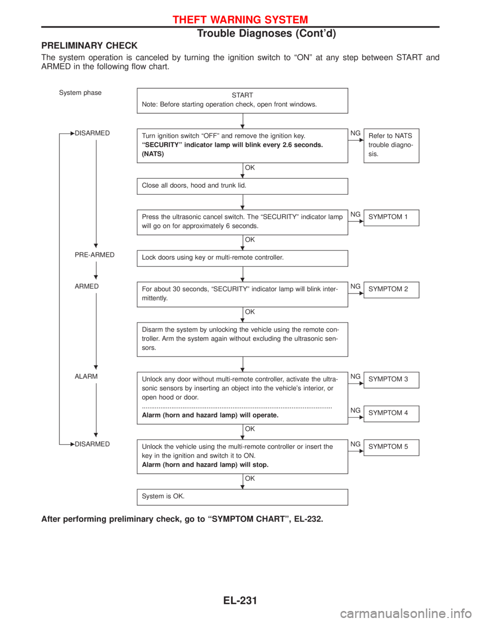
PRELIMINARY CHECK
The system operation is canceled by turning the ignition switch to ªONº at any step between START and
ARMED in the following flow chart.
System phase
START
Note: Before starting operation check, open front windows.
EDISARMED
Turn ignition switch ªOFFº and remove the ignition key.
ªSECURITYº indicator lamp will blink every 2.6 seconds.
(NATS)
OK
ENG
Refer to NATS
trouble diagno-
sis.
Close all doors, hood and trunk lid.
Press the ultrasonic cancel switch. The ªSECURITYº indicator lamp
will go on for approximately 6 seconds.
OK
ENG
SYMPTOM 1
PRE-ARMED
Lock doors using key or multi-remote controller.
ARMED
For about 30 seconds, ªSECURITYº indicator lamp will blink inter-
mittently.
OK
ENG
SYMPTOM 2
Disarm the system by unlocking the vehicle using the remote con-
troller. Arm the system again without excluding the ultrasonic sen-
sors.
ALARM
Unlock any door without multi-remote controller, activate the ultra-
sonic sensors by inserting an object into the vehicle's interior, or
open hood or door.
.......................................................................................................
Alarm (horn and hazard lamp) will operate.
OK
ENG
SYMPTOM 3
ENG
SYMPTOM 4
EDISARMED
Unlock the vehicle using the multi-remote controller or insert the
key in the ignition and switch it to ON.
Alarm (horn and hazard lamp) will stop.
OK
ENG
SYMPTOM 5
System is OK.
After performing preliminary check, go to ªSYMPTOM CHARTº, EL-232.
H
H
H
HH
HH
H
HH
HH
H
THEFT WARNING SYSTEM
Trouble Diagnoses (Cont'd)
EL-231
Page 1048 of 1767
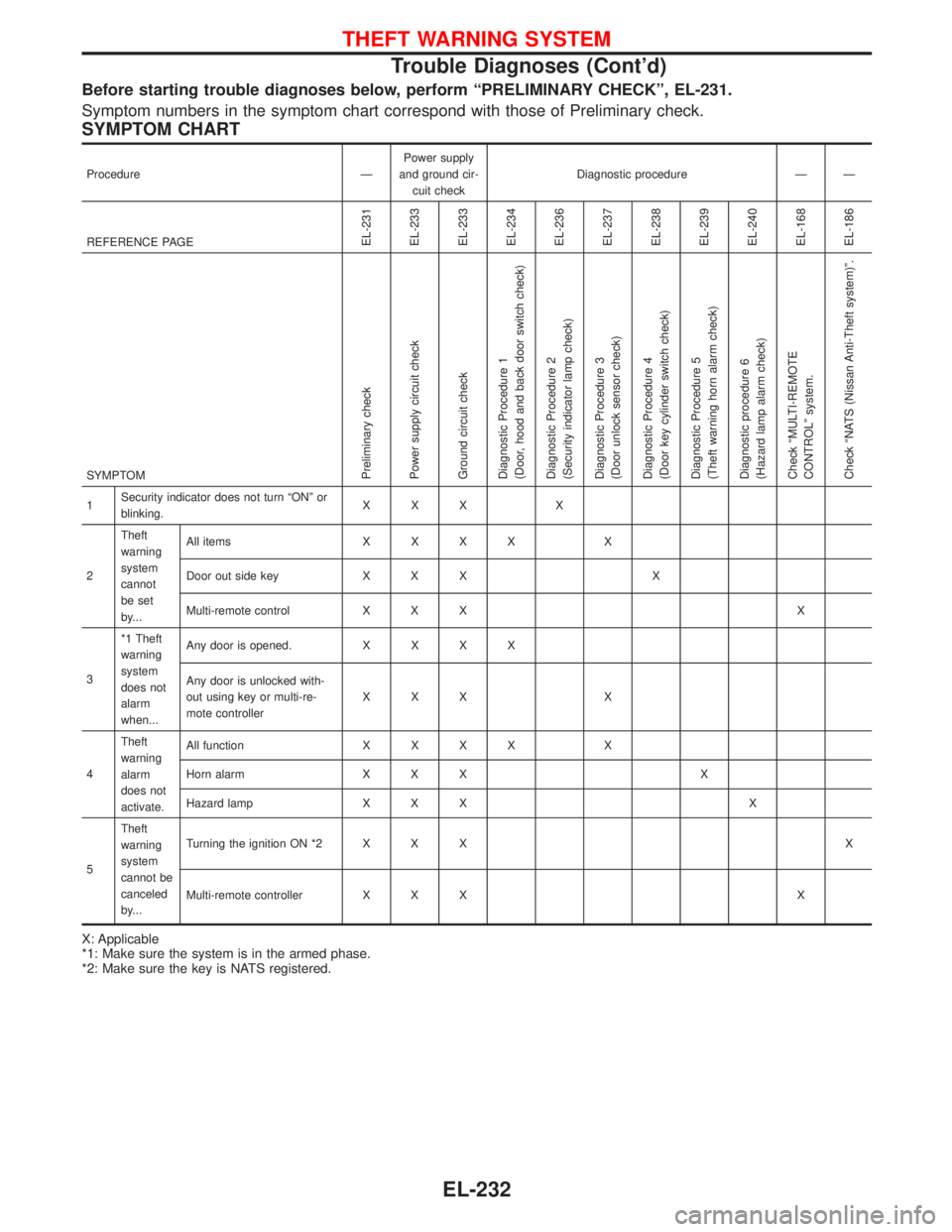
Before starting trouble diagnoses below, perform ªPRELIMINARY CHECKº, EL-231.
Symptom numbers in the symptom chart correspond with those of Preliminary check.
SYMPTOM CHART
Procedure ÐPower supply
and ground cir-
cuit checkDiagnostic procedure Ð Ð
REFERENCE PAGE
EL-231
EL-233
EL-233
EL-234
EL-236
EL-237
EL-238
EL-239
EL-240
EL-168
EL-186
SYMPTOMPreliminary check
Power supply circuit check
Ground circuit check
Diagnostic Procedure 1
(Door, hood and back door switch check)
Diagnostic Procedure 2
(Security indicator lamp check)
Diagnostic Procedure 3
(Door unlock sensor check)
Diagnostic Procedure 4
(Door key cylinder switch check)
Diagnostic Procedure 5
(Theft warning horn alarm check)
Diagnostic procedure 6
(Hazard lamp alarm check)
Check ªMULTI-REMOTE
CONTROLº system.
Check ªNATS (Nissan Anti-Theft system)º.
1Security indicator does not turn ªONº or
blinking.XXX X
2Theft
warning
system
cannot
be set
by...All itemsXXXX X
Door out side key X X X X
Multi-remote control X X X X
3*1 Theft
warning
system
does not
alarm
when...Any door is opened.XXXX
Any door is unlocked with-
out using key or multi-re-
mote controllerXXX X
4Theft
warning
alarm
does not
activate.All functionXXXX X
Horn alarm X X X X
Hazard lamp X X X X
5Theft
warning
system
cannot be
canceled
by...Turning the ignition ON *2 X X XX
Multi-remote controller X X X X
X: Applicable
*1: Make sure the system is in the armed phase.
*2: Make sure the key is NATS registered.
THEFT WARNING SYSTEM
Trouble Diagnoses (Cont'd)
EL-232
Page 1055 of 1767
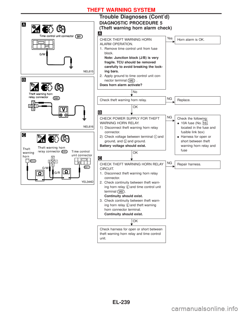
DIAGNOSTIC PROCEDURE 5
(Theft warning horn alarm check)
CHECK THEFT WARNING HORN
ALARM OPERATION.
1. Remove time control unit from fuse
block.
Note: Junction block (J/B) is very
fragile. TCU should be removed
carefully to avoid breaking the lock-
ing bars.
2. Apply ground to time control unit con-
nector terminal
U43.
Does horn alarm activate?
No
EYe s
Horn alarm is OK.
Check theft warning horn relay.
OK
ENG
Replace.
CHECK POWER SUPPLY FOR THEFT
WARNING HORN RELAY.
1) Disconnect theft warning horn relay
connector.
2) Check voltage between terminalq
1and
ground, andq
3and ground.
Battery voltage should exist.
OK
ENG
Check the following:
I10A fuse (No.
16 ,
located in the fuse and
fusible link box)
IHarness for open or
short between theft
warning horn relay and
fuse
CHECK THEFT WARNING HORN RELAY
CIRCUIT.
1. Disconnect theft warning horn relay
connector.
2. Check continuity between theft warn-
ing horn relayq
2and time control unit
terminal
U43.
Continuity should exist.
3. Check continuity between theft warn-
ing horn relayq
5and theft warning
horn connector terminal.
Continuity should exist.
OK
ENG
Repair harness.
Check harness for open or short between
theft warning horn relay and time control
unit.
NEL615
NEL616
YEL344D
H
H
H
H
THEFT WARNING SYSTEM
Trouble Diagnoses (Cont'd)
EL-239
Page 1107 of 1767
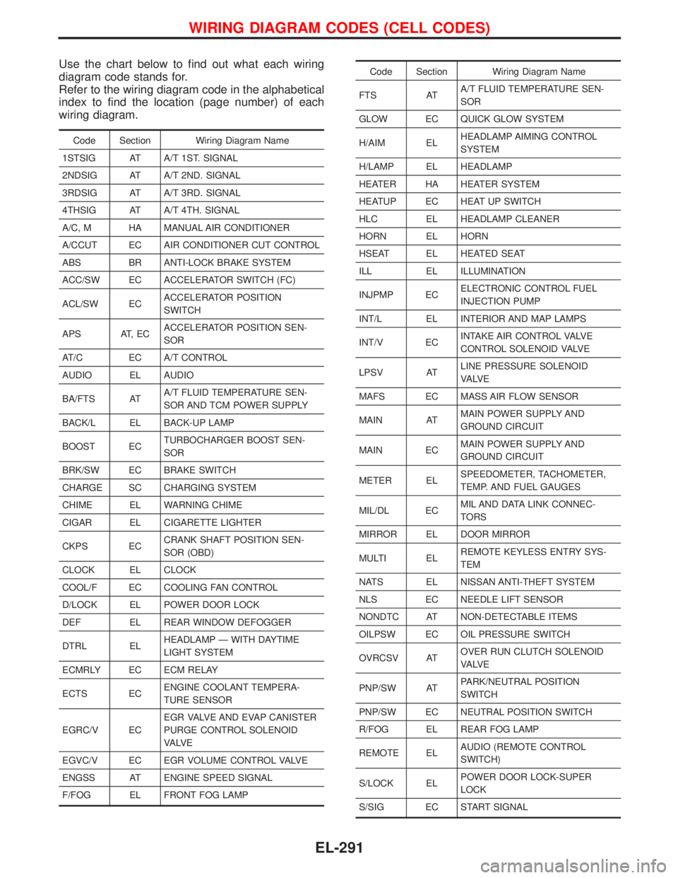
Use the chart below to find out what each wiring
diagram code stands for.
Refer to the wiring diagram code in the alphabetical
index to find the location (page number) of each
wiring diagram.
Code Section Wiring Diagram Name
1STSIG AT A/T 1ST. SIGNAL
2NDSIG AT A/T 2ND. SIGNAL
3RDSIG AT A/T 3RD. SIGNAL
4THSIG AT A/T 4TH. SIGNAL
A/C, M HA MANUAL AIR CONDITIONER
A/CCUT EC AIR CONDITIONER CUT CONTROL
ABS BR ANTI-LOCK BRAKE SYSTEM
ACC/SW EC ACCELERATOR SWITCH (FC)
ACL/SW ECACCELERATOR POSITION
SWITCH
APS AT, ECACCELERATOR POSITION SEN-
SOR
AT/C EC A/T CONTROL
AUDIO EL AUDIO
BA/FTS ATA/T FLUID TEMPERATURE SEN-
SOR AND TCM POWER SUPPLY
BACK/L EL BACK-UP LAMP
BOOST ECTURBOCHARGER BOOST SEN-
SOR
BRK/SW EC BRAKE SWITCH
CHARGE SC CHARGING SYSTEM
CHIME EL WARNING CHIME
CIGAR EL CIGARETTE LIGHTER
CKPS ECCRANK SHAFT POSITION SEN-
SOR (OBD)
CLOCK EL CLOCK
COOL/F EC COOLING FAN CONTROL
D/LOCK EL POWER DOOR LOCK
DEF EL REAR WINDOW DEFOGGER
DTRL ELHEADLAMP Ð WITH DAYTIME
LIGHT SYSTEM
ECMRLY EC ECM RELAY
ECTS ECENGINE COOLANT TEMPERA-
TURE SENSOR
EGRC/V ECEGR VALVE AND EVAP CANISTER
PURGE CONTROL SOLENOID
VA LV E
EGVC/V EC EGR VOLUME CONTROL VALVE
ENGSS AT ENGINE SPEED SIGNAL
F/FOG EL FRONT FOG LAMP
Code Section Wiring Diagram Name
FTS ATA/T FLUID TEMPERATURE SEN-
SOR
GLOW EC QUICK GLOW SYSTEM
H/AIM ELHEADLAMP AIMING CONTROL
SYSTEM
H/LAMP EL HEADLAMP
HEATER HA HEATER SYSTEM
HEATUP EC HEAT UP SWITCH
HLC EL HEADLAMP CLEANER
HORN EL HORN
HSEAT EL HEATED SEAT
ILL EL ILLUMINATION
INJPMP ECELECTRONIC CONTROL FUEL
INJECTION PUMP
INT/L EL INTERIOR AND MAP LAMPS
INT/V ECINTAKE AIR CONTROL VALVE
CONTROL SOLENOID VALVE
LPSV ATLINE PRESSURE SOLENOID
VA LV E
MAFS EC MASS AIR FLOW SENSOR
MAIN ATMAIN POWER SUPPLY AND
GROUND CIRCUIT
MAIN ECMAIN POWER SUPPLY AND
GROUND CIRCUIT
METER ELSPEEDOMETER, TACHOMETER,
TEMP. AND FUEL GAUGES
MIL/DL ECMIL AND DATA LINK CONNEC-
TORS
MIRROR EL DOOR MIRROR
MULTI ELREMOTE KEYLESS ENTRY SYS-
TEM
NATS EL NISSAN ANTI-THEFT SYSTEM
NLS EC NEEDLE LIFT SENSOR
NONDTC AT NON-DETECTABLE ITEMS
OILPSW EC OIL PRESSURE SWITCH
OVRCSV ATOVER RUN CLUTCH SOLENOID
VA LV E
PNP/SW ATPARK/NEUTRAL POSITION
SWITCH
PNP/SW EC NEUTRAL POSITION SWITCH
R/FOG EL REAR FOG LAMP
REMOTE ELAUDIO (REMOTE CONTROL
SWITCH)
S/LOCK ELPOWER DOOR LOCK-SUPER
LOCK
S/SIG EC START SIGNAL
WIRING DIAGRAM CODES (CELL CODES)
EL-291
Page 1183 of 1767
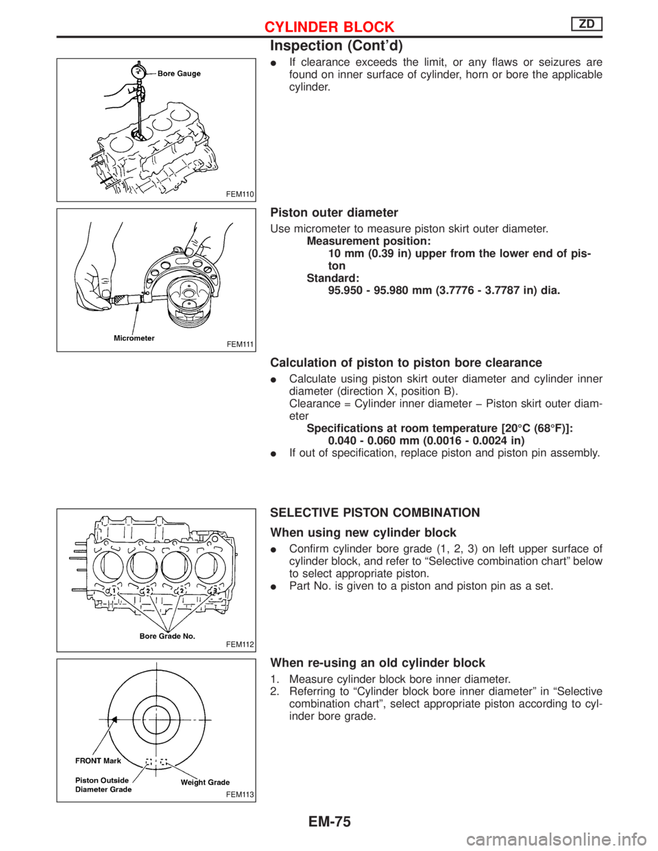
IIf clearance exceeds the limit, or any flaws or seizures are
found on inner surface of cylinder, horn or bore the applicable
cylinder.
Piston outer diameter
Use micrometer to measure piston skirt outer diameter.
Measurement position:
10 mm (0.39 in) upper from the lower end of pis-
ton
Standard:
95.950 - 95.980 mm (3.7776 - 3.7787 in) dia.
Calculation of piston to piston bore clearance
ICalculate using piston skirt outer diameter and cylinder inner
diameter (direction X, position B).
Clearance = Cylinder inner diameter þ Piston skirt outer diam-
eter
Specifications at room temperature [20ÉC (68ÉF)]:
0.040 - 0.060 mm (0.0016 - 0.0024 in)
IIf out of specification, replace piston and piston pin assembly.
SELECTIVE PISTON COMBINATION
When using new cylinder block
IConfirm cylinder bore grade (1, 2, 3) on left upper surface of
cylinder block, and refer to ªSelective combination chartº below
to select appropriate piston.
IPart No. is given to a piston and piston pin as a set.
When re-using an old cylinder block
1. Measure cylinder block bore inner diameter.
2. Referring to ªCylinder block bore inner diameterº in ªSelective
combination chartº, select appropriate piston according to cyl-
inder bore grade.
FEM110
FEM111
FEM112
FEM113
CYLINDER BLOCKZD
Inspection (Cont'd)
EM-75
Page 1419 of 1767
A
ABS (anti-lock brake system).........................BR-35
ABS - Wiring diagram ....................................BR-50
A/C air flow .......................................................HA-8
A/C compressor precaution..............................HA-5
A/C control operation (manual A/C) .................HA-6
A/C relay.........................................................HA-61
A/C symptom chart (manual A/C) ..................HA-36
A/C trouble diagnoses (manual A/C) .............HA-27
A/C, M - Wiring diagram ................................HA-43
ACC/SW - Wiring diagram ...........................EC-106
Accelerator control system ...........................FE-2, 5
Accelerator position sensor .........EC-130, 368, 371
Accelerator position switch ..................EC-369, 371
Accelerator switch (F/C) ...............................EC-104
Accelerator wire adjustment .............................FE-5
Accelerator work unit....................................EC-365
A/CCUT - Wiring diagram ............................EC-289
Air bag ..............................................................RS-6
Air bag disposal..............................................RS-20
Air bag precautions ...........................................GI-3
Air bleeding (hydraulic clutch) ..........................CL-6
Air bleeding for brake system ..........................BR-8
Air cleaner filter replacement ..............MA-5, 20, 24
Air conditioner cut control ..............EC-22, 311, 440
Air control cable adjustment...........................HA-62
Air flow meter - See Mass air flow
sensor .................................................EC-88, 356
Alternator ........................................................SC-27
Angular tightening application..........................EM-3
Antenna .................................................EL-111, 127
Anti-lock brake system - See ABS .................BR-37
Anti-lock brake system - Wiring
diagram .......................................................BR-50
APS - Wiring diagram ..................................EC-133
ASCD vacuum hose ......................................MA-40
A/T - Wiring diagram .........................................AT-7
A/T - Wiring diagram - AT - PNP/SW .............AT-87
A/T - Wiring diagram - AT - VSS A/T ..............AT-49
A/T control ....................................................EC-155
A/T diagnosis communication line ...............EC-155
A/T fluid checking ............................................AT-27
A/T fluid temperature sensor...........................AT-76
A/T mode switch..............................................AT-94
A/T self-diagnoses ....................................AT-14, 19
A/T Wiring diagram - AT - ENG SS ................AT-79
A/T Wiring diagram AT - BA/FTS ....................AT-75
A/T Wiring diagram AT - LPSV .......................AT-82
A/T Wiring diagram AT - OVRCSV .................AT-68
A/T Wiring diagram AT - SSV/A ......................AT-62
A/T Wiring diagram AT - SSV/B ......................AT-65
A/T Wiring diagram AT - TCV .........................AT-71
A/T Wiring diagram AT - TPS..........................AT-56
A/T Wiring diagram AT - VSSMTR .................AT-52
AT/C - Wiring diagram..................................EC-157
Audio......................................................EL-111, 113
AUDIO - Wiring diagram ...............................EL-115Audio and A/C control removal and
installation - See Instrument panel .............BT-16
Auto lock free running hub .............................FA-14
Automatic transmission number ......................GI-30
Axle housing (rear) ...........................................RA-8
B
Back Door .......................................................BT-14
Back door opener - See Back door ................BT-14
Back door trim.................................................BT-18
Back door window...........................................BT-43
Back-up lamp ..................................................EL-49
Back-up lamp switch (M/T) ........................MT-6, 10
BACK/L - Wiring diagram................................EL-49
Ball joint front axle ..........................................FA-36
Basic inspection .....................................EC-50, 338
Battery ..............................................................SC-3
Battery Voltage .............................................EC-153
Blower motor ..................................................HA-60
Blower resistor................................................HA-60
Body alignment ...............................................BT-49
BOOST - Wiring diagram .............................EC-217
Boring/horning cylinder block.........................EM-74
Brake booster .................................................BR-17
Brake fluid change ...........................................BR-5
Brake fluid level ...........................MA-17, 36, 40, 43
Brake fluid level and line check .......................BR-5
Brake hydraulic line......................................BR-5, 6
Brake inspection ..........................MA-36, 40, 41, 42
Brake lines and cables inspection.....MA-36, 40, 42
Brake lining wear temporary checking ....MA-36, 42
Brake master cylinder ....................................BR-16
Brake pedal ....................................................BR-14
Brake switch .................................................EC-400
BRK/SW - Wiring diagram ...........................EC-205
Bumper, front ....................................................BT-6
Bumper, rear .....................................................BT-8
C
Camshaft ........................................................EM-30
Camshaft position sensor (PUMP)...............EC-161
Center case (Transfer) ......................................TF-9
CHARGE - Wiring diagram ............................SC-24
Charge air pressure sensor .........................EC-215
Charging system ............................................SC-23
Chassis and body maintenance ....................MA-36
CIGAR - Wiring diagram ...............................EL-105
Cigarette lighter.............................................EL-104
Circuit breaker.................................................EL-17
CKPS - Wiring diagram ................................EC-147
Clock .............................................................EL-104
CLOCK - Wiring diagram ..............................EL-106
Clutch cover ..............................................CL-11, 12
Clutch disc ......................................................CL-11
Clutch fluid level ......................................MA-17, 36
Clutch master cylinder ..................................CL-7, 8
ALPHABETICAL INDEX
IDX-2
Page 1421 of 1767
F
Fan switch ......................................................HA-60
F/FOG - Wiring diagram .................................EL-51
Final drive disassembly............................PD-15, 37
Final drive pre-inspection .........................PD-15, 37
Final drive removal and installation ...............PD-15
Finisher, interior - See Trim ............................BT-18
Finisher, rear panel .........................................BT-18
Floor trim .........................................................BT-18
Fluid temperature sensor (A/T) .....................AT-141
Fluids .............................................MA-5, 17, 20, 36
Flywheel (clutch) .......................................CL-11, 12
Flywheel runout..............................................EM-94
Fog lamp, front .........................................EL-51, 53
Fog lamp, rear ................................................EL-54
Fork rod (M/T) ................................................MT-13
Forward clutch...............................................AT-157
Front axle ....................................................FA-4, 13
Front bumper ....................................................BT-6
Front case (Transfer) ..................................TF-9, 23
Front combination lamp removal and
installation .....................................................BT-6
Front disc brake .............................................BR-26
Front door .......................................................BT-10
Front Door Trim...............................................BT-19
Front drive shaft (Transfer) .........................TF-9, 19
Front final drive disassembly (4WD) ..............PD-14
Front final drive removal and installa-
tion (4WD) ............................................PD-12, 13
Front fog lamp ..........................................EL-51, 53
Front passenger air bag .................................RS-17
Front seat ........................................................BT-34
Front seat belt ..................................................RS-4
Front seat belt pre-tensioner ..........................RS-12
Front side air bag ...........................................RS-18
Front suspension ........................................FA-4, 29
Fuel cut control (at no load & high
engine speed) .....................................EC-22, 311
Fuel cut solenoid valve ................................EC-376
Fuel cut system ............................................EC-232
Fuel filler lid.......................................................BT-8
Fuel filter replacement...................MA-5, 20, 23, 33
Fuel gauge..................................FE-3, 6, EL-72, 80
Fuel injection system .............................EC-20, 306
Fuel injection timing feed back (Elec-
tronic Fuel Injection Pump) ......................EC-192
Fuel precautions ................................................GI-6
Fuel pump and gauge ..............................FE-3, 6, 7
Fuel system ..................................................FE-3, 6
Fuel tank .......................................................FE-3, 6
Fuel temperature sensor ......................EC-123, 372
Fuse ................................................................EL-17
Fuse and fusible link box .............................Foldout
Fuse block ....................................................Foldout
Fusible link ......................................................EL-17GGarage jack and safety stand .........................GI-32
Gauges .....................................................EL-70, 71
Gear components (M/T) ........MT-11, 14, 16, 21, 23
Generator - See Alternator .............................SC-27
GLOW - Wiring diagram...............................EC-241
Glow control system.....................EC-239, 311, 389
Glow plug .............................................EC-239, 390
Glow relay ............................................EC-241, 396
Grease .........................................MA-17, 39, 40, 44
Ground distribution..........................................EL-18
H
Harness connector ............................................EL-3
Harness connector inspection .........................GI-19
Harness layout ............EL-247, 248, 264, 276, 278,
286, 287, 288, 289, 290
Hazard warning lamp................................EL-55, 56
Headlamp ......EL-26, 29, 30, 31, 37, 38, 39, 42, 43
Headlamp aiming control .............EL-37, 38, 39, 42
Headlamp washer .........................................EL-100
Headlining - See Roof trim .............................BT-20
Heat up switch..............................................EC-258
Heated seat .......................................BT-36, EL-128
HEATER - Wiring diagram .............................HA-41
HEATUP - Wiring diagram ...........................EC-259
Height (Dimensions) ........................................GI-10
HFC134a (R134a) system precaution .............HA-3
HFC134a (R134a) system service
procedure....................................................HA-15
HFC134a (R134a) system service tools ........HA-11
High clutch ....................................................AT-155
H/LAMP - Wiring diagram ............EL-26, 31, 39, 56
Hood..................................................................BT-6
Hood lock system .............................................BT-6
Horn ..............................................................EL-104
HORN - Wiring diagram................................EL-104
How to erase DTC for OBD system ......EC-33, 321
HSEAT - Wiring diagram...............................EL-128
I
Identification .....................................................HA-2
Identification plate .....................................GI-29, 30
Idle speed...............................................EC-50, 338
Idle speed inspection ...............................MA-20, 26
ILL - Wiring diagram .......................................EL-62
Illumination ................................................EL-61, 62
Injection nozzle ......................................EC-24, 313
Injection nozzle inspection ..................MA-5, 20, 25
Injection timing control valve ........................EC-380
INJPMP - Wiring diagram ...EC-126, 164, 171, 178,
185, 195, 235
Instrument panel .............................................BT-16
INT/L - Wiring diagram....................................EL-66
ALPHABETICAL INDEX
IDX-4
Page 1462 of 1767
Shown below are Pre-delivery Inspection items required for the new vehicle. It is recommended that
necessary items other than those listed here be added, paying due regard to the conditions in each
country.
Perform applicable items on each model. Consult text of this section for specifications.
UNDER HOOD Ð engine off
lRadiator coolant level and coolant hose connections for leaks
lBattery fluid level, specific gravity and conditions of battery terminals
lBrake and clutch reservoirs fluid level and fluid lines for leaks
lWindshield and rear window washer and headlamp cleaner reservoir fluid level
lDrive belts tension
lFuel filter for water or dust, and fuel lines and connections for leaks
lPower steering reservoir fluid level and hose connections for leaks
lEngine oil level and oil leaks
INSIDE AND OUTSIDE
lOperation of all instruments, gauges, lights, anti-theft system and accessories
lOperation of horn(s), wiper and washer
lSteering lock for operation
lAir conditioner for gas leaks
lFront and rear seats, and seat belts for operation
lAll moldings, trims and fittings for fit and alignment
lAll windows for operation and alignment
lHood, tailgate, door panels for fit and alignment
lLatches, keys and locks for operation
lWeatherstrips for adhesion and fit
lHeadlamp aiming
lTighten wheel nuts
lTire pressure (Inc. spare tire)
lCheck front wheels for toe-in
lInstall clock/room lamp fuse
lRemove wiper blade protectors (if necessary)
UNDER BODY
lManual transmission/transaxle and differential gear oil level
lBrake and fuel lines and oil/fluid reservoirs for leaks
lTighten bolts and nuts of steering linkage and gear box, suspension, propeller shafts and drive shafts
ROAD TEST
lClutch operation
lParking brake operation
lService brake operation
lSteering control and returnability
lEngine performance
lSqueaks and rattles
ENGINE OPERATING AND HOT
lAdjust idle mixture and speed (and ignition timing) (Petrol only)
FINAL INSPECTION
lInstall necessary parts (outside mirror, wheel covers, seat belts, mat, carpet or mud flaps)
lInspect for interior and exterior metal and paint damage
lCheck for spare tire, jack, tools and literature
lWash, clean interior and exterior
PRE-DELIVERY INSPECTION ITEMS
MA-3