2002 NISSAN TERRANO audio
[x] Cancel search: audioPage 817 of 1767

ELECTRICAL SYSTEM
SECTION
EL
When you read wiring diagrams:
IRead GI section, ªHOW TO READ WIRING DIAGRAMSº.
CONTENTS
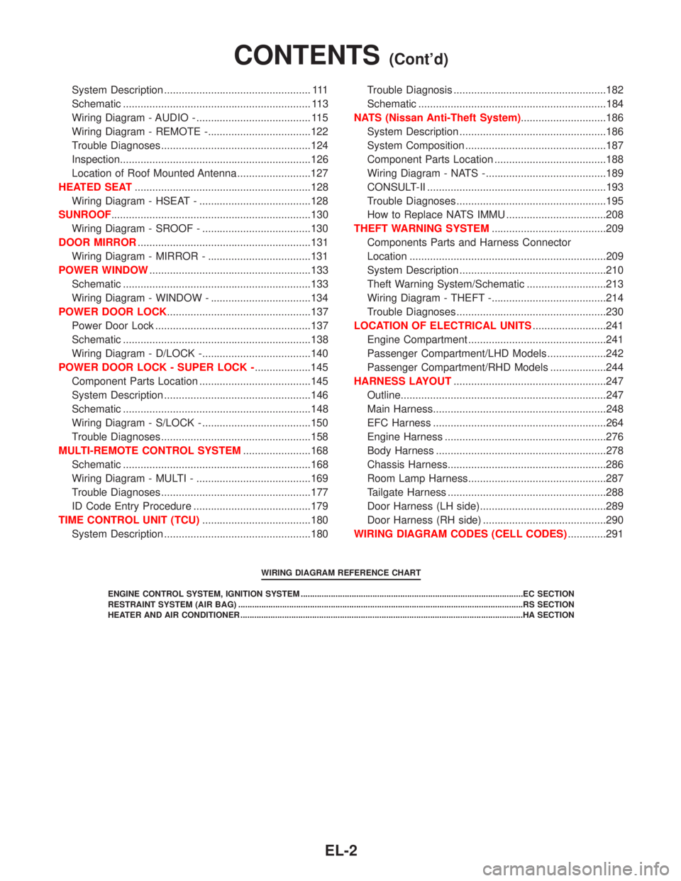
HARNESS CONNECTOR................................................3
Description ...................................................................3
STANDARDIZED RELAYS..............................................4
Description ...................................................................4
POWER SUPPLY ROUTING...........................................6
Schematic ....................................................................6
Wiring Diagram - POWER - ........................................8
Fuse ...........................................................................17
Fusible Link................................................................17
Circuit Breaker Inspection .........................................17
GROUND DISTRIBUTION.............................................18
COMBINATION SWITCH...............................................23
Check .........................................................................23
Replacement ..............................................................24
STEERING SWITCH......................................................25
Check .........................................................................25
HEADLAMP - Without Daytime Light System -.........26
Wiring Diagram - H/LAMP -.......................................26
HEADLAMP - Daytime Light System -.......................29
Operation ...................................................................29
Schematic ..................................................................30
Wiring Diagram - DTRL - ...........................................31
HEADLAMP - Headlamp Aiming Control -.................37
Description .................................................................37
Replacing Headlamp Aiming Actuator .......................38
Wiring Diagram - H/AIM - ..........................................39
Trouble Diagnoses.....................................................42
HEADLAMP...................................................................43
Bulb Replacement .....................................................43
Aiming Adjustment .....................................................43
EXTERIOR LAMP..........................................................45
Wiring Diagram - TAIL/L - ..........................................45
Wiring Diagram - STOP/L - .......................................48
Wiring Diagram - BACK/L - .......................................49
Wiring Diagram - F/FOG - .........................................51
Front Fog Lamp Aiming Adjustment ..........................53
Wiring Diagram - R/FOG -.........................................54
Schematic ..................................................................55Wiring Diagram - TURN - ..........................................56
Bulb Specifications ....................................................60
INTERIOR LAMP...........................................................61
Schematic ..................................................................61
Wiring Diagram - ILL - ...............................................62
Wiring Diagram - INT/L - ...........................................66
METER AND GAUGES.................................................70
Combination Meter ....................................................70
Schematic ..................................................................71
Wiring Diagram - METER - .......................................72
Combination Meter Self-Diagnosis ............................76
Components Inspection .............................................78
Trouble Diagnoses.....................................................79
Fuel Tank Gauge Unit Check ....................................80
Thermal Transmitter Check .......................................80
Oil Pressure Switch Check ........................................80
WARNING LAMPS AND CHIME...................................81
Schematic ..................................................................81
Wiring Diagram - WARN - .........................................82
Diode Check ..............................................................92
Wiring Diagram - CHIME - ........................................93
WIPER AND WASHER..................................................94
Wiring Diagram - WIPER - ........................................94
Wiring Diagram - WIP/R -..........................................96
Installation ..................................................................98
Washer Nozzle Adjustment .......................................99
Check Valve ...............................................................99
Wiring Diagram - HLC - ...........................................100
HORN, CIGARETTE LIGHTER AND CLOCK............104
Wiring Diagram - HORN - .......................................104
Wiring Diagram - CIGAR -.......................................105
Wiring Diagram - CLOCK -......................................106
REAR WINDOW DEFOGGER AND DOOR
MIRROR DEFOGGER.................................................107
Wiring Diagram - DEF - ...........................................107
Filament Check ........................................................109
Filament Repair ....................................................... 110
AUDIO.......................................................................... 111
Page 818 of 1767

System Description .................................................. 111
Schematic ................................................................ 113
Wiring Diagram - AUDIO - ....................................... 115
Wiring Diagram - REMOTE -...................................122
Trouble Diagnoses...................................................124
Inspection.................................................................126
Location of Roof Mounted Antenna .........................127
HEATED SEAT............................................................128
Wiring Diagram - HSEAT - ......................................128
SUNROOF....................................................................130
Wiring Diagram - SROOF - .....................................130
DOOR MIRROR...........................................................131
Wiring Diagram - MIRROR - ...................................131
POWER WINDOW.......................................................133
Schematic ................................................................133
Wiring Diagram - WINDOW - ..................................134
POWER DOOR LOCK.................................................137
Power Door Lock .....................................................137
Schematic ................................................................138
Wiring Diagram - D/LOCK -.....................................140
POWER DOOR LOCK - SUPER LOCK -...................145
Component Parts Location ......................................145
System Description ..................................................146
Schematic ................................................................148
Wiring Diagram - S/LOCK - .....................................150
Trouble Diagnoses...................................................158
MULTI-REMOTE CONTROL SYSTEM.......................168
Schematic ................................................................168
Wiring Diagram - MULTI - .......................................169
Trouble Diagnoses...................................................177
ID Code Entry Procedure ........................................179
TIME CONTROL UNIT (TCU).....................................180
System Description ..................................................180Trouble Diagnosis ....................................................182
Schematic ................................................................184
NATS (Nissan Anti-Theft System).............................186
System Description ..................................................186
System Composition ................................................187
Component Parts Location ......................................188
Wiring Diagram - NATS -.........................................189
CONSULT-II .............................................................193
Trouble Diagnoses...................................................195
How to Replace NATS IMMU ..................................208
THEFT WARNING SYSTEM.......................................209
Components Parts and Harness Connector
Location ...................................................................209
System Description ..................................................210
Theft Warning System/Schematic ...........................213
Wiring Diagram - THEFT -.......................................214
Trouble Diagnoses...................................................230
LOCATION OF ELECTRICAL UNITS.........................241
Engine Compartment ...............................................241
Passenger Compartment/LHD Models ....................242
Passenger Compartment/RHD Models ...................244
HARNESS LAYOUT....................................................247
Outline......................................................................247
Main Harness...........................................................248
EFC Harness ...........................................................264
Engine Harness .......................................................276
Body Harness ..........................................................278
Chassis Harness......................................................286
Room Lamp Harness...............................................287
Tailgate Harness ......................................................288
Door Harness (LH side)...........................................289
Door Harness (RH side) ..........................................290
WIRING DIAGRAM CODES (CELL CODES).............291
WIRING DIAGRAM REFERENCE CHART
ENGINE CONTROL SYSTEM, IGNITION SYSTEM ................................................................................................EC SECTION
RESTRAINT SYSTEM (AIR BAG) ...........................................................................................................................RS SECTION
HEATER AND AIR CONDITIONER ..........................................................................................................................HA SECTION
CONTENTS(Cont'd)
EL-2
Page 834 of 1767

EFC HARNESS LHD MODELS
GROUND CONNECT TOCONN.
NO.CELL CODE
F129/F128 4WD SWITCH (TD27Ti) E150 EL-WARN
BRAKE SWITCH F101 EC-BRK/SW
DATA LINK CONNECTOR F115 EC-MIL/DL
ECM F134EC-MAIN, EC-VSS, EC-BRK/SW,
EC-MIL/DL
NATS IMMU (TD27Ti) F58 EL-NATS
VEHICLE SPEED SENSOR E140 EC-VSS, EL-METER
F47/F36 AIR BAG DIAGNOSIS SENSOR UNIT B106 RS-SRS
BRAKE FLUID LEVEL SWITCH F3 EL-WARN
COMBINATION METER F118EC-VSS, AT-VSSMTR, EL-H/LAMP,
EL-DTRL, EL-F/FOG, EL-R/FOG,
EL-ILL, EL-TURN, EL-METER,
EL-WARN, EL-CLOCK, BR-ABS,
RS-SRS
COOLING FAN MOTOR F40 EC-COOL/F
DATA LINK CONNECTOR F115 EC-MIL/DL, AT-NONDTC
FRONT FOG LAMP LH F44 EL-F/FOG
FRONT TURN SIGNAL LAMP LH F37 EL-TURN, EL-THEFT
FUSE BLOCK (J/B) F114EL-F/FOG, EL-INT/L, EL-TURN,
EL-CHIME, EL-DEF, EL-SROOF,
EL-WINDOW, EL-D/LOCK, EL-S/
LOCK, EL-MULTI, EL-THEFT,
HA-A/C, M, HA-HEATER
HAZARD SWITCH (TYPE 1) F140 EL-TURN
HAZARD SWITCH (TYPE 2) F152 EL-TURN
HEADLAMP AIMING MOTOR LH F43 EL-H/AIM
HEADLAMP CLEANER MOTOR F103 EL-HLC
HEADLAMP LH F42 EL-H/LAMP, EL-DTRL
HEADLAMP RELAY LH F111 EL-H/LAMP, EL-DTRL
PARKING LAMP LH F41 EL-TAIL/L
SIDE TURN SIGNAL LAMP LH F104 EL-TURN, EL-THEFT
F53 AUDIO UNIT (TYPE 1) F139 EL-ILL, EL-AUDIO
AUDIO UNIT (TYPE 2) F153 EL-ILL, EL-AUDIO, EL-REMOTE
CD AUDIO CHANGER F155 EL-AUDIO
F2 ABS ACTUATOR AND ELECTRIC UNIT (CONTROL UNIT) F29 BR-ABS
EFC HARNESS RHD MODELS
GROUND CONNECT TOCONN.
NO.CELL CODE
F47/F36 FRONT FOG LAMP LH F44 EL-F/FOG
FRONT TURN SIGNAL LAMP LH F37 EL-TURN, EL-THEFT
HEADLAMP AIMING MOTOR LH F43 EL-H/AIM
HEADLAMP CLEANER MOTOR F103 EL-HLC
HEADLAMP LH F42 EL-H/LAMP
HEADLAMP RELAY LH F111 EL-H/LAMP
PARKING LAMP LH F41 EL-TAIL/L
SIDE TURN SIGNAL LAMP LH F104 EL-TURN, EL-THEFT
F2 ABS ACTUATOR AND ELECTRIC UNIT (CONTROL UNIT) F29 BR-ABS
GROUND DISTRIBUTION
EL-18
Page 836 of 1767

MAIN HARNESS RHD MODELS
GROUND CONNECT TOCONN.
NO.CELL CODE
M846/M845 4WD SWITCH (TD27Ti) E150 EL-WARN
BRAKE SWITCH M750 EC-BRK/SW
DATA LINK CONNECTOR M832 EC-MIL/DL
DONGLE CONTROL UNIT (TD27Ti) M720 EL-AUDIO, EL-NATS
ECM M852EC-MAIN, EC-VSS, EC-BRK/SW,
EC-MIL/DL
NATS IMMU (TD27Ti) M831 EL-NATS
VEHICLE SPEED SENSOR E140 EC-VSS, EL-METER
M754/M33
A/C CONTROL PANEL (FAN SWITCH) M770EC-A/CCUT, HA-A/C, M,
HA-HEATER
A/C CONTROL PANEL M771EL-ILL, EL-DEF, HA-A/C, M,
HA-HEATER
A/T MODE SWITCH M732 AT-NONDTC
ACCESSORY RELAY M803 EL-CIGAR
AIR BAG DIAGNOSIS SENSOR UNIT B106 RS-SRS
AMBIENT LIGHT CONSOLE M769 EL-ILL
ASHTRAY ILLUMINATION M137 EL-ILL
BRAKE FLUID LEVEL SWITCH M507 EL-WARN
CIGARETTE LIGHTER SOCKET M141 EL-CIGAR
COMBINATION METER M837EC-VSS, AT-VSSMTR, EL-H/LAMP,
EL-F/FOG, EL-R/FOG, EL-ILL,
EL-TURN, EL-METER, EL-WARN,
EL-CLOCK, BR-ABS, RS-SRS
COMBINATION SWITCH (TURN SIGNAL SWITCH) M817 EL-TURN
COMBINATION SWITCH (WIPER AND WASHER SWITCH) M816 EL-WIPER, EL-WIP/R, EL-HLC
COOLING FAN MOTOR M19 EC-COOL/F
DATA LINK CONNECTOR M832 EC-MIL/DL, AT-NONDTC
FRONT FOG LAMP RH M38 EL-F/FOG
FRONT TURN SIGNAL LAMP RH M39 EL-TURN, EL-THEFT
FRONT WIPER MOTOR M502 EL-WIPER
FUSE BLOCK (J/B) M835EL-F/FOG, EL-INT/L, EL-TURN,
EL-CHIME, EL-DEF, EL-SROOF,
EL-WINDOW, EL-S/LOCK,
EL-MULTI, EL-THEFT, HA-A/C, M,
HA-A/C, M, HA-HEATER
GLOVE BOX LAMP SWITCH M143 EL-ILL
HAZARD SWITCH (TYPE 1) M855 EL-TURN
HAZARD SWITCH (TYPE 2) M873 EL-TURN
HEADLAMP AIMING MOTOR RH M41 EL-H/AIM
HEADLAMP RELAY RH M824 EL-H/LAMP
HEADLAMP RH M42 EL-H/LAMP
HOOD SWITCH M84 EL-THEFT
PARK/NEUTRAL POSITION RELAY M729 EC-PNP/SW, SC-START
PARKING LAMP RH M43 EL-TAIL/L
REAR FOG LAMP RELAY M820 EL-R/FOG
SIDE TURN SIGNAL LAMP RH M801 EL-TURN, EL-THEFT
ULTRASONIC CANCEL SWITCH M117 EL-THEFT
M761 AUDIO UNIT (TYPE 1) M854 EL-ILL, EL-AUDIO
AUDIO UNIT (TYPE 2) M874 EL-ILL, EL-AUDIO, EL-REMOTE
CD AUTO CHANGER M876 EL-AUDIO
GROUND DISTRIBUTION
EL-20
Page 837 of 1767

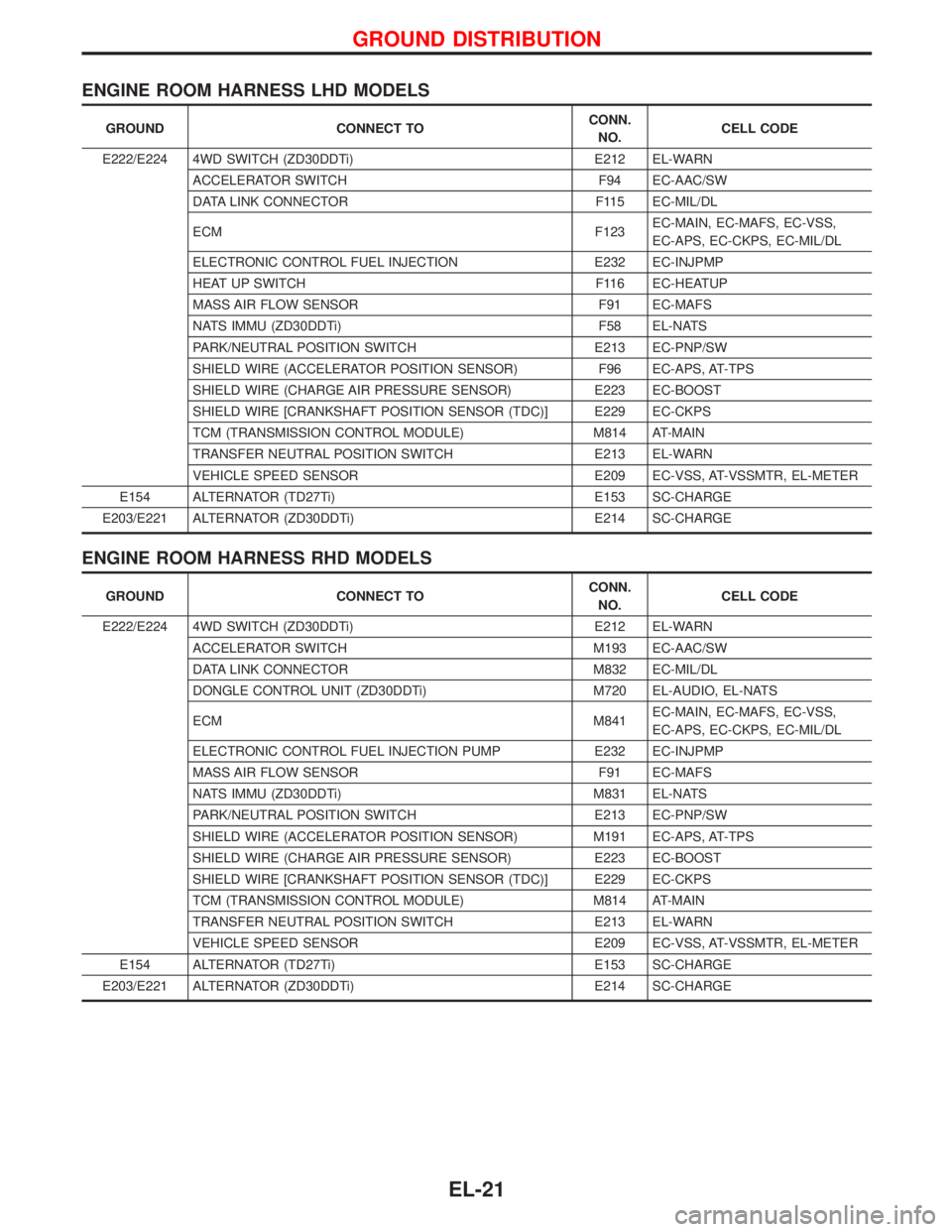
ENGINE ROOM HARNESS LHD MODELS
GROUND CONNECT TOCONN.
NO.CELL CODE
E222/E224 4WD SWITCH (ZD30DDTi) E212 EL-WARN
ACCELERATOR SWITCH F94 EC-AAC/SW
DATA LINK CONNECTOR F115 EC-MIL/DL
ECM F123EC-MAIN, EC-MAFS, EC-VSS,
EC-APS, EC-CKPS, EC-MIL/DL
ELECTRONIC CONTROL FUEL INJECTION E232 EC-INJPMP
HEAT UP SWITCH F116 EC-HEATUP
MASS AIR FLOW SENSOR F91 EC-MAFS
NATS IMMU (ZD30DDTi) F58 EL-NATS
PARK/NEUTRAL POSITION SWITCH E213 EC-PNP/SW
SHIELD WIRE (ACCELERATOR POSITION SENSOR) F96 EC-APS, AT-TPS
SHIELD WIRE (CHARGE AIR PRESSURE SENSOR) E223 EC-BOOST
SHIELD WIRE [CRANKSHAFT POSITION SENSOR (TDC)] E229 EC-CKPS
TCM (TRANSMISSION CONTROL MODULE) M814 AT-MAIN
TRANSFER NEUTRAL POSITION SWITCH E213 EL-WARN
VEHICLE SPEED SENSOR E209 EC-VSS, AT-VSSMTR, EL-METER
E154 ALTERNATOR (TD27Ti) E153 SC-CHARGE
E203/E221 ALTERNATOR (ZD30DDTi) E214 SC-CHARGE
ENGINE ROOM HARNESS RHD MODELS
GROUND CONNECT TOCONN.
NO.CELL CODE
E222/E224 4WD SWITCH (ZD30DDTi) E212 EL-WARN
ACCELERATOR SWITCH M193 EC-AAC/SW
DATA LINK CONNECTOR M832 EC-MIL/DL
DONGLE CONTROL UNIT (ZD30DDTi) M720 EL-AUDIO, EL-NATS
ECM M841EC-MAIN, EC-MAFS, EC-VSS,
EC-APS, EC-CKPS, EC-MIL/DL
ELECTRONIC CONTROL FUEL INJECTION PUMP E232 EC-INJPMP
MASS AIR FLOW SENSOR F91 EC-MAFS
NATS IMMU (ZD30DDTi) M831 EL-NATS
PARK/NEUTRAL POSITION SWITCH E213 EC-PNP/SW
SHIELD WIRE (ACCELERATOR POSITION SENSOR) M191 EC-APS, AT-TPS
SHIELD WIRE (CHARGE AIR PRESSURE SENSOR) E223 EC-BOOST
SHIELD WIRE [CRANKSHAFT POSITION SENSOR (TDC)] E229 EC-CKPS
TCM (TRANSMISSION CONTROL MODULE) M814 AT-MAIN
TRANSFER NEUTRAL POSITION SWITCH E213 EL-WARN
VEHICLE SPEED SENSOR E209 EC-VSS, AT-VSSMTR, EL-METER
E154 ALTERNATOR (TD27Ti) E153 SC-CHARGE
E203/E221 ALTERNATOR (ZD30DDTi) E214 SC-CHARGE
GROUND DISTRIBUTION
EL-21
Page 927 of 1767

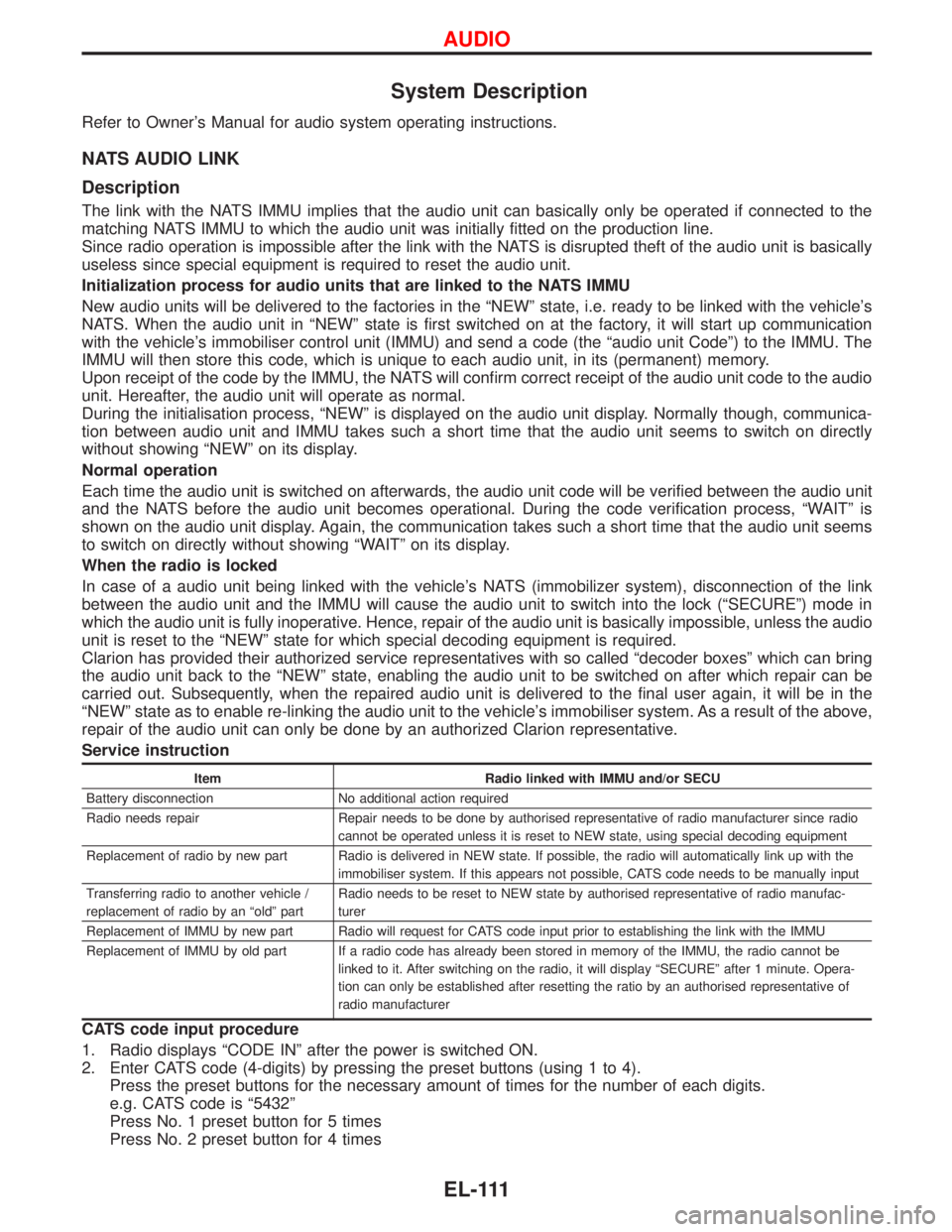
System Description
Refer to Owner's Manual for audio system operating instructions.
NATS AUDIO LINK
Description
The link with the NATS IMMU implies that the audio unit can basically only be operated if connected to the
matching NATS IMMU to which the audio unit was initially fitted on the production line.
Since radio operation is impossible after the link with the NATS is disrupted theft of the audio unit is basically
useless since special equipment is required to reset the audio unit.
Initialization process for audio units that are linked to the NATS IMMU
New audio units will be delivered to the factories in the ªNEWº state, i.e. ready to be linked with the vehicle's
NATS. When the audio unit in ªNEWº state is first switched on at the factory, it will start up communication
with the vehicle's immobiliser control unit (IMMU) and send a code (the ªaudio unit Codeº) to the IMMU. The
IMMU will then store this code, which is unique to each audio unit, in its (permanent) memory.
Upon receipt of the code by the IMMU, the NATS will confirm correct receipt of the audio unit code to the audio
unit. Hereafter, the audio unit will operate as normal.
During the initialisation process, ªNEWº is displayed on the audio unit display. Normally though, communica-
tion between audio unit and IMMU takes such a short time that the audio unit seems to switch on directly
without showing ªNEWº on its display.
Normal operation
Each time the audio unit is switched on afterwards, the audio unit code will be verified between the audio unit
and the NATS before the audio unit becomes operational. During the code verification process, ªWAITº is
shown on the audio unit display. Again, the communication takes such a short time that the audio unit seems
to switch on directly without showing ªWAITº on its display.
When the radio is locked
In case of a audio unit being linked with the vehicle's NATS (immobilizer system), disconnection of the link
between the audio unit and the IMMU will cause the audio unit to switch into the lock (ªSECUREº) mode in
which the audio unit is fully inoperative. Hence, repair of the audio unit is basically impossible, unless the audio
unit is reset to the ªNEWº state for which special decoding equipment is required.
Clarion has provided their authorized service representatives with so called ªdecoder boxesº which can bring
the audio unit back to the ªNEWº state, enabling the audio unit to be switched on after which repair can be
carried out. Subsequently, when the repaired audio unit is delivered to the final user again, it will be in the
ªNEWº state as to enable re-linking the audio unit to the vehicle's immobiliser system. As a result of the above,
repair of the audio unit can only be done by an authorized Clarion representative.
Service instruction
Item Radio linked with IMMU and/or SECU
Battery disconnection No additional action required
Radio needs repair Repair needs to be done by authorised representative of radio manufacturer since radio
cannot be operated unless it is reset to NEW state, using special decoding equipment
Replacement of radio by new part Radio is delivered in NEW state. If possible, the radio will automatically link up with the
immobiliser system. If this appears not possible, CATS code needs to be manually input
Transferring radio to another vehicle /
replacement of radio by an ªoldº partRadio needs to be reset to NEW state by authorised representative of radio manufac-
turer
Replacement of IMMU by new part Radio will request for CATS code input prior to establishing the link with the IMMU
Replacement of IMMU by old part If a radio code has already been stored in memory of the IMMU, the radio cannot be
linked to it. After switching on the radio, it will display ªSECUREº after 1 minute. Opera-
tion can only be established after resetting the ratio by an authorised representative of
radio manufacturer
CATS code input procedure
1. Radio displays ªCODE INº after the power is switched ON.
2. Enter CATS code (4-digits) by pressing the preset buttons (using 1 to 4).
Press the preset buttons for the necessary amount of times for the number of each digits.
e.g. CATS code is ª5432º
Press No. 1 preset button for 5 times
Press No. 2 preset button for 4 times
AUDIO
EL-111
Page 928 of 1767

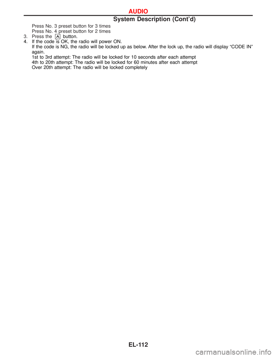
Press No. 3 preset button for 3 times
Press No. 4 preset button for 2 times
3. Press the
button.
4. If the code is OK, the radio will power ON.
If the code is NG, the radio will be locked up as below. After the lock up, the radio will display ªCODE INº
again.
1st to 3rd attempt: The radio will be locked for 10 seconds after each attempt
4th to 20th attempt: The radio will be locked for 60 minutes after each attempt
Over 20th attempt: The radio will be locked completely
AUDIO
System Description (Cont'd)
EL-112
Page 929 of 1767

Schematic
TYPE 1
YEL122D
AUDIO
EL-113