2002 NISSAN TERRANO ABS
[x] Cancel search: ABSPage 203 of 1767
BRAKE SYSTEM
SECTION
BR
CONTENTS
PRECAUTIONS AND PREPARATION............................3
Supplement Restraint System (SRS)²AIR BAG²
and²SEAT BELT PRE-TENSIONER².........................3
Precautions ..................................................................3
Preparation ..................................................................4
CHECK AND ADJUSTMENT..........................................5
Checking Brake Fluid Level.........................................5
Checking Brake Line ...................................................5
Changing Brake Fluid ..................................................5
Brake Burnishing Procedure........................................5
BRAKE HYDRAULIC LINE.............................................6
Bleeding Brake System ...............................................8
Removal .......................................................................9
Inspection.....................................................................9
Installation ....................................................................9
LOAD SENSING VALVE...............................................10
Removal and Installation ...........................................10
Removal ..................................................................... 11
Installation .................................................................. 11
Inspection and Adjustment ........................................12
BRAKE PEDAL AND BRACKET..................................14
Removal and Installation ...........................................14
Inspection...................................................................15
Adjustment .................................................................15
MASTER CYLINDER.....................................................16
Removal .....................................................................16
Installation ..................................................................16
BRAKE BOOSTER........................................................17
Removal and Installation ...........................................17
Inspection...................................................................17
Installation ..................................................................18
VACUUM HOSE.............................................................19
Removal and Installation ...........................................19
Inspection...................................................................21
VACUUM PUMP (TD27Ti engine model)....................23
Removal and Installation ...........................................23
Inspection...................................................................23VACUUM PUMP (ZD30DDTi engine model)...............25
Removal and Installation ...........................................25
FRONT DISC BRAKE...................................................26
Pad Replacement ......................................................26
Removal .....................................................................27
Disassembly...............................................................27
Inspection...................................................................27
Assembly ...................................................................28
Inspection...................................................................28
Installation ..................................................................30
REAR DRUM BRAKE...................................................31
Removal .....................................................................32
Shoe Replacement ....................................................33
Inspection...................................................................33
Installation ..................................................................33
PARKING BRAKE CONTROL......................................35
Removal and Installation ...........................................35
Inspection...................................................................35
Adjustment .................................................................35
ANTI-LOCK BRAKE SYSTEM......................................37
Purpose......................................................................37
Operation ...................................................................37
ABS Hydraulic Circuit ................................................37
System Description ....................................................38
Removal and Installation ...........................................42
TROUBLE DIAGNOSES...............................................47
How to Perform Trouble Diagnoses for Quick
and Accurate Repair ..................................................47
Component Parts and Harness Connector
Location .....................................................................48
Circuit Diagram for Quick Pinpoint Check.................49
Wiring Diagram - ABS - .............................................50
CONSULT-II ...............................................................58
CONSULT-II Inspection Procedure............................59
Preliminary Check......................................................65
Ground Circuit Check ................................................66
Diagnostic Procedure 1 (Not self-diagnostic item) ....67
Page 204 of 1767
Diagnostic Procedure 2 (Warning lamp stays on
when ignition switch is turned ON)............................69
Diagnostic Procedure 3 (ABS actuator solenoid
valve and solenoid valve relay) .................................71
Diagnostic Procedure 4 (Wheel sensor or rotor) ......73
Diagnostic Procedure 5 (Motor Relay or motor) .......75
Diagnostic Procedure 7 (Low voltage) ......................77
Diagnostic Procedure 8 (G sensor) ...........................78
Diagnostic Procedure 9 (Control unit) .......................79
Diagnostic Procedure 10 (Pedal vibration and
noise) .........................................................................80Diagnostic Procedure 11 (Long stopping
distance) ....................................................................80
Diagnostic Procedure 12 (Unexpected pedal
action) ........................................................................81
Diagnostic Procedure 13 ...........................................82
Diagnostic Procedure 14 ...........................................82
Electrical Components Inspection .............................83
SERVICE DATA AND SPECIFICATIONS (SDS)..........84
General Specifications ...............................................84
Inspection and Adjustment ........................................85
CONTENTS(Cont'd)
BR-2
Page 208 of 1767

W/O ABS
YBR256
BRAKE HYDRAULIC LINE
BR-6
Page 209 of 1767

WITH ABS
YBR257
BRAKE HYDRAULIC LINE
BR-7
Page 210 of 1767
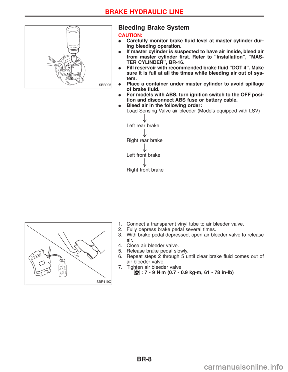
Bleeding Brake System
CAUTION:
ICarefully monitor brake fluid level at master cylinder dur-
ing bleeding operation.
IIf master cylinder is suspected to have air inside, bleed air
from master cylinder first. Refer to ªInstallationº, ªMAS-
TER CYLINDERº, BR-16.
IFill reservoir with recommended brake fluid ªDOT 4º. Make
sure it is full at all the times while bleeding air out of sys-
tem.
IPlace a container under master cylinder to avoid spillage
of brake fluid.
IFor models with ABS, turn ignition switch to the OFF posi-
tion and disconnect ABS fuse or battery cable.
IBleed air in the following order:
Load Sensing Valve air bleeder (Models equipped with LSV)
"
Left rear brake
"
Right rear brake
"
Left front brake
"
Right front brake
1. Connect a transparent vinyl tube to air bleeder valve.
2. Fully depress brake pedal several times.
3. With brake pedal depressed, open air bleeder valve to release
air.
4. Close air bleeder valve.
5. Release brake pedal slowly.
6. Repeat steps 2 through 5 until clear brake fluid comes out of
air bleeder valve.
7. Tighten air bleeder valve
:7-9N×m (0.7 - 0.9 kg-m, 61 - 78 in-lb)
SBR995
SBR419C
BRAKE HYDRAULIC LINE
BR-8
Page 239 of 1767
Purpose
The Anti-lock Brake System (ABS) with an integrated Electronic Brake force Distribution (EBD) system con-
sists of electronic and hydraulic components. It allows you to control the braking force so that wheel lock can
be avoided during braking.
The advantages of ABS with EBD
1) Better tracking performance through improved steering wheel control.
2) Improved maneuverability and safer vehicle control.
3) Improved vehicle stability by preventing flat spins.
4) Shorter stopping distance and optimal utilisation of the rear brakes under many different circumstances.
Operation
IABS with EBD has self-test capabilities. The ABS warning lamp is illuminated for 1 second each time the
ignition switch is turned ªONº. After the engine is started, the ABS warning lamp turns off. An ABS self-test
is performed the first time the vehicle reaches 6 km/h (4 MPH) to ensure the system is operational. A
mechanical noise may be heard as the ABS performs this self-test and is a normal part of the self-test
feature. If a malfunction is detected during this check, the ABS warning lamp will stay on.
During the self-test, it also performs a EBD check when it detects a failure the ABS warning light will go
on simultaneously with the brake warning light and an audible sound will sound constantly.
IEBD system will only operate when the ABS is not in active status and it uses the inlet valves of ABS con-
trol unit to limit the pressure to the rear wheels when they tend to go into slip.
IWhen the vehicle speed is less than 10 km/h (6 MPH) the ABS system does not operate.
IWhile driving, a mechanical noise may be heard during ABS operation, this is a normal system condition.
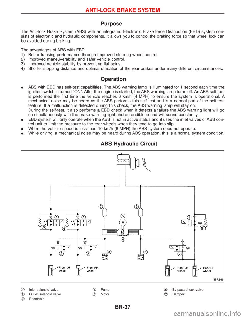
ABS Hydraulic Circuit
q1Inlet solenoid valve
q
2Outlet solenoid valve
q
3Reservoirq
4Pump
q
5Motorq
6By pass check valve
q
7Damper
NBR346
ANTI-LOCK BRAKE SYSTEM
BR-37
Page 240 of 1767
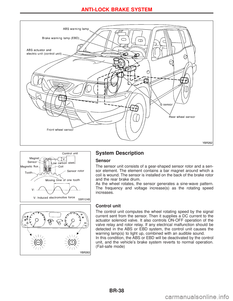
System Description
Sensor
The sensor unit consists of a gear-shaped sensor rotor and a sen-
sor element. The element contains a bar magnet around which a
coil is wound. The sensor is installed on the back of the brake rotor
and the rear brake drum.
As the wheel rotates, the sensor generates a sine-wave pattern.
The frequency and voltage increase(s) as the rotating speed
increases.
Control unit
The control unit computes the wheel rotating speed by the signal
current sent from the sensor. Then it supplies a DC current to the
actuator solenoid valve. It also controls ON-OFF operation of the
valve relay and rotor relay. If any electrical malfunction should be
detected in the ABS or EBD system, the control unit causes the
warning lamp(s) to light up, combined with an audible sound.
In this condition, the ABS or EBD will be deactivated by the control
unit, and the vehicle's brake system reverts to normal operation.
(Fail-safe mode)
YBR262
SBR124B
YBR263
ANTI-LOCK BRAKE SYSTEM
BR-38
Page 241 of 1767

G SENSOR
The G sensor analyses deceleration during braking to determine whether the vehicle is being driven on a road
with low surface resistance () (snow-covered road, etc.). The ABS control unit uses the signal from the
deceleration sensor to compensate for road surface conditions when controlling the braking operation.
NBR136
ANTI-LOCK BRAKE SYSTEM
System Description (Cont'd)
BR-39