2002 NISSAN TERRANO cooling
[x] Cancel search: coolingPage 1 of 1767

Edition: February 2002
Release: February 2002 (01)
Publication No.: SM2E00-1R20E0E
GENERAL INFORMATIONGI
MAINTENANCEMA
ENGINE MECHANICALEM
ENGINE LUBRICATION &
COOLING SYSTEMSLC
ENGINE CONTROL SYSTEMEC
ACCELERATOR CONTROL,
FUEL & EXHAUST SYSTEMFE
CLUTCHCL
MANUAL TRANSMISSIONMT
AUTOMATIC TRANSMISSIONAT
TRANSFERTF
PROPELLER SHAFT &
DIFFERENTIAL CARRIERPD
FRONT AXLE & FRONT SUSPENSIONFA
REAR AXLE & REAR SUSPENSIONRA
BRAKE SYSTEMBR
STEERING SYSTEMST
RESTRAINT SYSTEMRS
BODY & TRIMBT
HEATER & AIR CONDITIONERHA
STARTING & CHARGING SYSTEMSSC
ELECTRICAL SYSTEMEL
ALPHABETICAL INDEXIDX
TERRANO
MODEL R20 SERIES
NISSAN EUROPE N.V.
NISSAN EUROPE N.V.
Produced in The Netherlands
QUICK REFERENCE INDEX
Page 6 of 1767
Supplemental Restraint System (SRS) ªAIR
BAGº and ªSEAT BELT PRE-TENSIONERº
The Supplemental Restraint System such as ªAIR BAGº and ªSEAT BELT PRE-TENSIONERº used along with
a seat belt, helps to reduce the risk or severity of injury to the driver and front passenger in a frontal collision.
The SRS system composition which is available to NISSAN MODEL R20 is as follows (The composition var-
ies according to the destination.):
Driver air bag module (located in the center of the steering wheel), front passenger air bag module (located
on the instrument panel on passenger side), seat belt pre-tensioner, a diagnosis sensor unit, warning lamp,
wiring harness and spiral cable.
Information necessary to service the system safely is included in theRS sectionof this Service Manual.
WARNING:
ITo avoid rendering the SRS inoperative, which could increase the risk of personal injury or death
in the event of a collision which would result in air bag inflation, all maintenance must be performed
by an authorized NISSAN dealer.
IImproper maintenance, including incorrect removal and installation of the SRS, can lead to per-
sonal injury caused by unintentional activation of the system. For removal of Spiral Cable and Air
Bag Module, see the RS section.
IDo not use electrical test equipment on any circuit related to the SRS unless instructed to in this
Service Manual. Spiral cable and wiring harnesses covered with yellow insulation either just before
the harness connectors or for the complete harness are related to the SRS.
Precautions
IBefore proceeding with disassembly, thoroughly clean the outside of the transmission. It is important to
prevent the internal parts from becoming contaminated by dirt or other foreign matter.
IDisassembly should be done in a clean work area.
IUse lint-free cloth or towels for wiping parts clean. Common shop rags can leave fibers that could inter-
fere with the operation of the transmission.
IPlace disassembled parts in order for easier and proper assembly.
IAll parts should be carefully cleaned with a general purpose, non-flammable solvent before inspection or
reassembly.
IGaskets, seals and O-rings should be replaced any time the transmission is disassembled.
IIt is very important to perform functional tests whenever they are indicated.
IThe valve body contains precision parts and requires extreme care when parts are removed and serviced.
Place removed parts in a parts rack in order to replace them in correct positions and sequences. Care will
also prevent springs and small parts from becoming scattered or lost.
IProperly installed valves, sleeves, plugs, etc. will slide along bores in valve body under their own weight.
IBefore assembly, apply a coat of recommended ATF to all parts. Apply petroleum jelly to protect O-rings
and seals, and to hold bearings and washers in place during assembly. Do not use grease.
IExtreme care should be taken to avoid damage to O-rings, seals and gaskets when assembling.
IAfter overhaul, refill the transmission with new ATF.
IWhen the A/T drain plug is removed, only some of the fluid is drained. Old A/T fluid will remain in torque
converter and ATF cooling system.
Always follow the procedures under ªChanging A/T Fluidº in the MA section when changing A/T fluid.
PREPARATION AND PRECAUTIONS
AT- 4
Page 126 of 1767
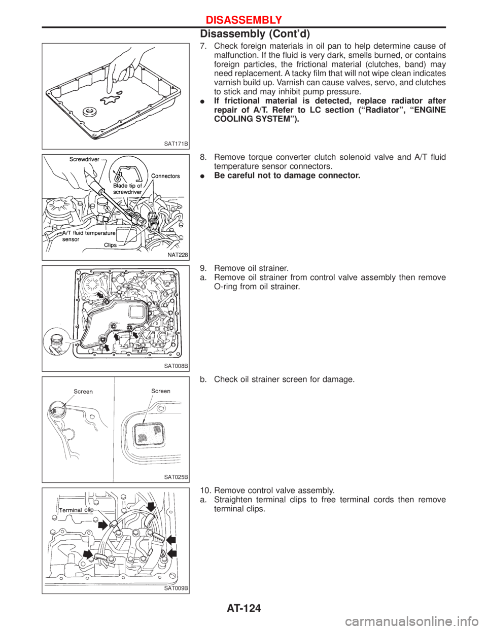
7. Check foreign materials in oil pan to help determine cause of
malfunction. If the fluid is very dark, smells burned, or contains
foreign particles, the frictional material (clutches, band) may
need replacement. A tacky film that will not wipe clean indicates
varnish build up. Varnish can cause valves, servo, and clutches
to stick and may inhibit pump pressure.
IIf frictional material is detected, replace radiator after
repair of A/T. Refer to LC section (ªRadiatorº, ªENGINE
COOLING SYSTEMº).
8. Remove torque converter clutch solenoid valve and A/T fluid
temperature sensor connectors.
IBe careful not to damage connector.
9. Remove oil strainer.
a. Remove oil strainer from control valve assembly then remove
O-ring from oil strainer.
b. Check oil strainer screen for damage.
10. Remove control valve assembly.
a. Straighten terminal clips to free terminal cords then remove
terminal clips.
SAT171B
NAT228
SAT008B
SAT025B
SAT009B
DISASSEMBLY
Disassembly (Cont'd)
AT-124
Page 381 of 1767
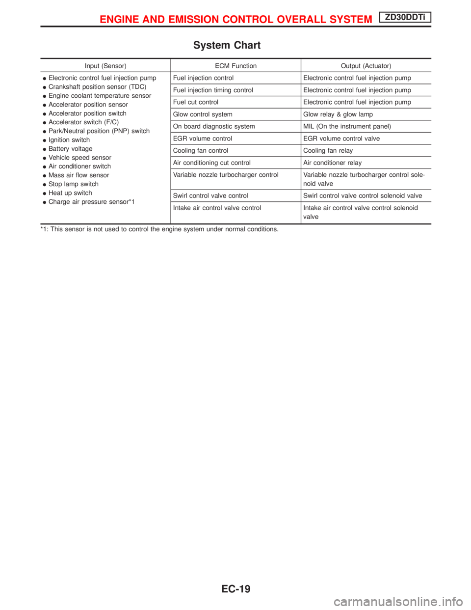
System Chart
Input (Sensor) ECM Function Output (Actuator)
IElectronic control fuel injection pump
ICrankshaft position sensor (TDC)
IEngine coolant temperature sensor
IAccelerator position sensor
IAccelerator position switch
IAccelerator switch (F/C)
IPark/Neutral position (PNP) switch
IIgnition switch
IBattery voltage
IVehicle speed sensor
IAir conditioner switch
IMass air flow sensor
IStop lamp switch
IHeat up switch
ICharge air pressure sensor*1Fuel injection control Electronic control fuel injection pump
Fuel injection timing control Electronic control fuel injection pump
Fuel cut control Electronic control fuel injection pump
Glow control system Glow relay & glow lamp
On board diagnostic system MIL (On the instrument panel)
EGR volume control EGR volume control valve
Cooling fan control Cooling fan relay
Air conditioning cut control Air conditioner relay
Variable nozzle turbocharger control Variable nozzle turbocharger control sole-
noid valve
Swirl control valve control Swirl control valve control solenoid valve
Intake air control valve control Intake air control valve control solenoid
valve
*1: This sensor is not used to control the engine system under normal conditions.
ENGINE AND EMISSION CONTROL OVERALL SYSTEMZD30DDTi
EC-19
Page 390 of 1767
REMOVAL
1. Remove the following:
IEngine coolant draining
ICharge air cooler
IAir inlet pipe
IThrottle body
IRocker cover
IOil level gauge guide
IEGR cooler
IEGR guide tube
IEGR volume control solenoid valve
IFuel hose
IInjection tube
IRadiator upper hose
IRadiator shroud
ICooling fan
IDrive belt
IVacuum pipe
IVacuum pump
2. Move the power steering pump.
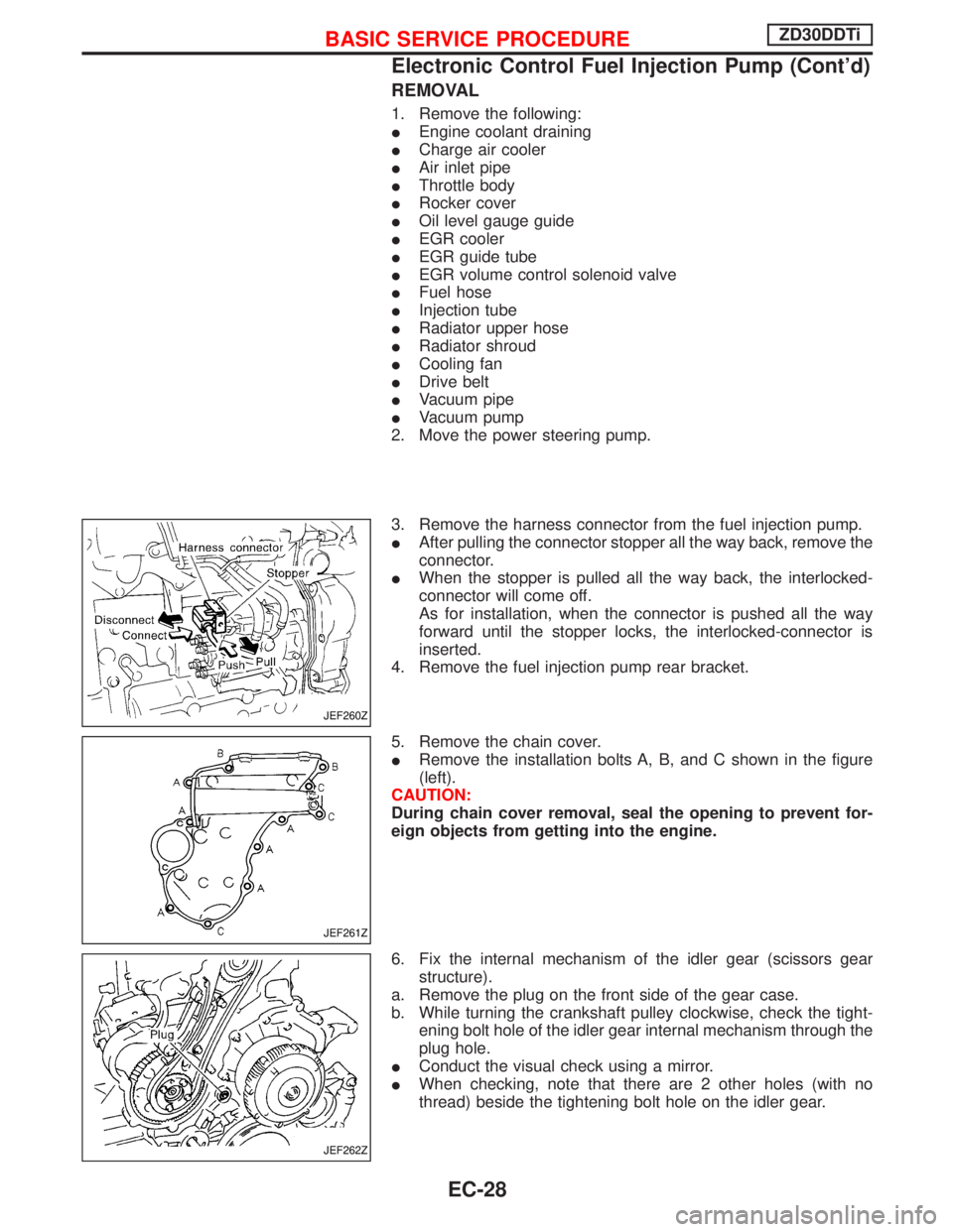
3. Remove the harness connector from the fuel injection pump.
IAfter pulling the connector stopper all the way back, remove the
connector.
IWhen the stopper is pulled all the way back, the interlocked-
connector will come off.
As for installation, when the connector is pushed all the way
forward until the stopper locks, the interlocked-connector is
inserted.
4. Remove the fuel injection pump rear bracket.
5. Remove the chain cover.
IRemove the installation bolts A, B, and C shown in the figure
(left).
CAUTION:
During chain cover removal, seal the opening to prevent for-
eign objects from getting into the engine.
6. Fix the internal mechanism of the idler gear (scissors gear
structure).
a. Remove the plug on the front side of the gear case.
b. While turning the crankshaft pulley clockwise, check the tight-
ening bolt hole of the idler gear internal mechanism through the
plug hole.
IConduct the visual check using a mirror.
IWhen checking, note that there are 2 other holes (with no
thread) beside the tightening bolt hole on the idler gear.
JEF260Z
JEF261Z
JEF262Z
BASIC SERVICE PROCEDUREZD30DDTi
Electronic Control Fuel Injection Pump (Cont'd)
EC-28
Page 402 of 1767
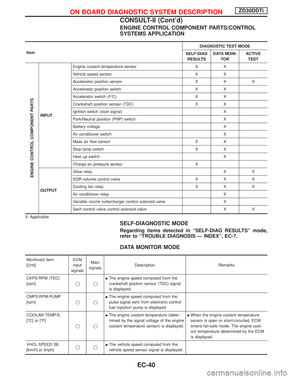
ENGINE CONTROL COMPONENT PARTS/CONTROL
SYSTEMS APPLICATION
ItemDIAGNOSTIC TEST MODE
SELF-DIAG
RESULTSDATA MONI-
TORACTIVE
TEST
ENGINE CONTROL COMPONENT PARTS
INPUTEngine coolant temperature sensor X X
Vehicle speed sensor X X
Accelerator position sensor X X X
Accelerator position switch X X
Accelerator switch (F/C) X X
Crankshaft position sensor (TDC) X X
Ignition switch (start signal) X
Park/Neutral position (PNP) switch X
Battery voltage X
Air conditioner switch X
Mass air flow sensor X X
Stop lamp switch X X
Heat up switch X
Charge air pressure sensor X
OUTPUTGlow relayXX
EGR volume control valve X X X
Cooling fan relay X X X
Air conditioner relay X
Variable nozzle turbocharger control solenoid valve X
Swirl control valve control solenoid valve X X
X: Applicable
SELF-DIAGNOSTIC MODE
Regarding items detected in ªSELF-DIAG RESULTSº mode,
refer to ªTROUBLE DIAGNOSIS Ð INDEXº, EC-7.
DATA MONITOR MODE
Monitored item
[Unit]ECM
input
signalsMain
signalsDescription Remarks
CKPS×RPM (TDC)
[rpm]qqIThe engine speed computed from the
crankshaft position sensor (TDC) signal
is displayed.
CMPS×RPM×PUMP
[rpm]qqIThe engine speed computed from the
pulse signal sent from electronic control
fuel injection pump is displayed.
COOLAN TEMP/S
[ÉC] or [ÉF]
qqIThe engine coolant temperature (deter-
mined by the signal voltage of the engine
coolant temperature sensor) is displayed.IWhen the engine coolant temperature
sensor is open or short-circuited, ECM
enters fail-safe mode. The engine cool-
ant temperature determined by the ECM
is displayed.
VHCL SPEED SE
[km/h] or [mph]qqIThe vehicle speed computed from the
vehicle speed sensor signal is displayed.
ON BOARD DIAGNOSTIC SYSTEM DESCRIPTIONZD30DDTi
CONSULT-II (Cont'd)
EC-40
Page 403 of 1767
![NISSAN TERRANO 2002 Service Repair Manual Monitored item
[Unit]ECM
input
signalsMain
signalsDescription Remarks
FUEL TEMP SEN
[ÉC] or [ÉF]qqIThe fuel temperature (sent from elec-
tronic control fuel injection pump) is dis-
played.
ACCEL POS NISSAN TERRANO 2002 Service Repair Manual Monitored item
[Unit]ECM
input
signalsMain
signalsDescription Remarks
FUEL TEMP SEN
[ÉC] or [ÉF]qqIThe fuel temperature (sent from elec-
tronic control fuel injection pump) is dis-
played.
ACCEL POS](/manual-img/5/57393/w960_57393-402.png)
Monitored item
[Unit]ECM
input
signalsMain
signalsDescription Remarks
FUEL TEMP SEN
[ÉC] or [ÉF]qqIThe fuel temperature (sent from elec-
tronic control fuel injection pump) is dis-
played.
ACCEL POS SEN [V]
qqIThe accelerator position sensor signal
voltage is displayed.
FULL ACCEL SW
[ON/OFF]qqIIndicates [ON/OFF] condition from the
accelerator position switch signal.
ACCEL SW (FC)
[OPEN/CLOSE]qqIIndicates [OPEN/CLOSE] condition from
the accelerator switch (FC) signal.
OFF ACCEL SW
[ON/OFF]qqIIndicates [ON/OFF] condition from the
accelerator position switch signal.
SPILL/V [ÉCA]
qIThe control position of spill valve (sent
from electronic control fuel injection
pump) is displayed.
BATTERY VOLT [V]
qqIThe power supply voltage of ECM is dis-
played.
P/N POSI SW
[ON/OFF]qqIIndicates [ON/OFF] condition from the
park/neutral position switch signal.
START SIGNAL
[ON/OFF]qqIIndicates [ON/OFF] condition from the
starter signal.IAfter starting the engine, [OFF] is dis-
played regardless of the starter signal.
AIR COND SIG
[ON/OFF]qqIIndicates [ON/OFF] condition of the air
conditioner switch as determined by the
air conditioner signal.
BRAKE SW [ON/OFF]
qqIIndicates [ON/OFF] condition from the
stop lamp switch signal.
IGN SW
[ON/OFF]qqIIndicates [ON/OFF] condition from igni-
tion switch signal.
WARM UP SW
[ON/OFF]qIIndicates [ON/OFF] condition from the
heat up switch signal.
MAS AIR/FL SE [V]
qqIThe signal voltage of the mass air flow
sensor is displayed.IWhen the engine is stopped, a certain
value is indicated.
DECELER F/CUT
[ON/OFF]qIThe [ON/OFF] condition from decelera-
tion fuel cut signal (sent from electronic
control fuel injection pump) is displayed.
INJ TIMG C/V [%]
qIThe duty ratio of fuel injection timing
control valve (sent from electronic control
fuel injection pump) is displayed.
AIR COND RLY
[ON/OFF]qIIndicates the control condition of the air
conditioner relay (determined by ECM
according to the input signals).
GLOW RLY [ON/OFF]
qIThe glow relay control condition (deter-
mined by ECM according to the input
signal) is displayed.
COOLING FAN
[ON/OFF]
qIIndicates the control condition of the
cooling fans (determined by ECM
according to the input signal).
ION ... Operates.
OFF ... Stopped.
ON BOARD DIAGNOSTIC SYSTEM DESCRIPTIONZD30DDTi
CONSULT-II (Cont'd)
EC-41
Page 405 of 1767
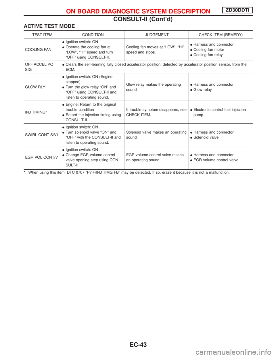
ACTIVE TEST MODE
TEST ITEM CONDITION JUDGEMENT CHECK ITEM (REMEDY)
COOLING FANIIgnition switch: ON
IOperate the cooling fan at
ªLOWº, ªHIº speed and turn
ªOFFº using CONSULT-II.Cooling fan moves at ªLOWº, ªHIº
speed and stops.IHarness and connector
ICooling fan motor
ICooling fan relay
OFF ACCEL PO
SIGIClears the self-learning fully closed accelerator position, detected by accelerator position sensor, from the
ECM.
GLOW RLYIIgnition switch: ON (Engine
stopped)
ITurn the glow relay ªONº and
ªOFFº using CONSULT-II and
listen to operating sound.Glow relay makes the operating
sound.IHarness and connector
IGlow relay
INJ TIMING*IEngine: Return to the original
trouble condition
IRetard the injection timing using
CONSULT-II.If trouble symptom disappears, see
CHECK ITEM.IElectronic control fuel injection
pump
SWIRL CONT S/V1IIgnition switch: ON
ITurn solenoid valve ªONº and
ªOFFº with the CONSULT-II and
listen to operating sound.Solenoid valve makes an operating
sound.IHarness and connector
ISolenoid valve
EGR VOL CONT/VIIgnition switch: ON
IChange EGR volume control
valve opening step using CON-
SULT-II.EGR volume control valve makes
an operating sound.IHarness and connector
IEGR volume control valve
*: When using this item, DTC 0707 ªP7×F/INJ TIMG FBº may be detected. If so, erase it because it is not a malfunction.
ON BOARD DIAGNOSTIC SYSTEM DESCRIPTIONZD30DDTi
CONSULT-II (Cont'd)
EC-43