2002 NISSAN TERRANO instrument panel
[x] Cancel search: instrument panelPage 6 of 1767
Supplemental Restraint System (SRS) ªAIR
BAGº and ªSEAT BELT PRE-TENSIONERº
The Supplemental Restraint System such as ªAIR BAGº and ªSEAT BELT PRE-TENSIONERº used along with
a seat belt, helps to reduce the risk or severity of injury to the driver and front passenger in a frontal collision.
The SRS system composition which is available to NISSAN MODEL R20 is as follows (The composition var-
ies according to the destination.):
Driver air bag module (located in the center of the steering wheel), front passenger air bag module (located
on the instrument panel on passenger side), seat belt pre-tensioner, a diagnosis sensor unit, warning lamp,
wiring harness and spiral cable.
Information necessary to service the system safely is included in theRS sectionof this Service Manual.
WARNING:
ITo avoid rendering the SRS inoperative, which could increase the risk of personal injury or death
in the event of a collision which would result in air bag inflation, all maintenance must be performed
by an authorized NISSAN dealer.
IImproper maintenance, including incorrect removal and installation of the SRS, can lead to per-
sonal injury caused by unintentional activation of the system. For removal of Spiral Cable and Air
Bag Module, see the RS section.
IDo not use electrical test equipment on any circuit related to the SRS unless instructed to in this
Service Manual. Spiral cable and wiring harnesses covered with yellow insulation either just before
the harness connectors or for the complete harness are related to the SRS.
Precautions
IBefore proceeding with disassembly, thoroughly clean the outside of the transmission. It is important to
prevent the internal parts from becoming contaminated by dirt or other foreign matter.
IDisassembly should be done in a clean work area.
IUse lint-free cloth or towels for wiping parts clean. Common shop rags can leave fibers that could inter-
fere with the operation of the transmission.
IPlace disassembled parts in order for easier and proper assembly.
IAll parts should be carefully cleaned with a general purpose, non-flammable solvent before inspection or
reassembly.
IGaskets, seals and O-rings should be replaced any time the transmission is disassembled.
IIt is very important to perform functional tests whenever they are indicated.
IThe valve body contains precision parts and requires extreme care when parts are removed and serviced.
Place removed parts in a parts rack in order to replace them in correct positions and sequences. Care will
also prevent springs and small parts from becoming scattered or lost.
IProperly installed valves, sleeves, plugs, etc. will slide along bores in valve body under their own weight.
IBefore assembly, apply a coat of recommended ATF to all parts. Apply petroleum jelly to protect O-rings
and seals, and to hold bearings and washers in place during assembly. Do not use grease.
IExtreme care should be taken to avoid damage to O-rings, seals and gaskets when assembling.
IAfter overhaul, refill the transmission with new ATF.
IWhen the A/T drain plug is removed, only some of the fluid is drained. Old A/T fluid will remain in torque
converter and ATF cooling system.
Always follow the procedures under ªChanging A/T Fluidº in the MA section when changing A/T fluid.
PREPARATION AND PRECAUTIONS
AT- 4
Page 38 of 1767
3. CRUISE TEST
ICheck all items listed in Parts 1 through 3.
With CONSULT-II
IUsing CONSULT-II, conduct a cruise test and record the result.
IPrint the result and ensure that shifts and lock-ups take place
as per ªShift Scheduleº.
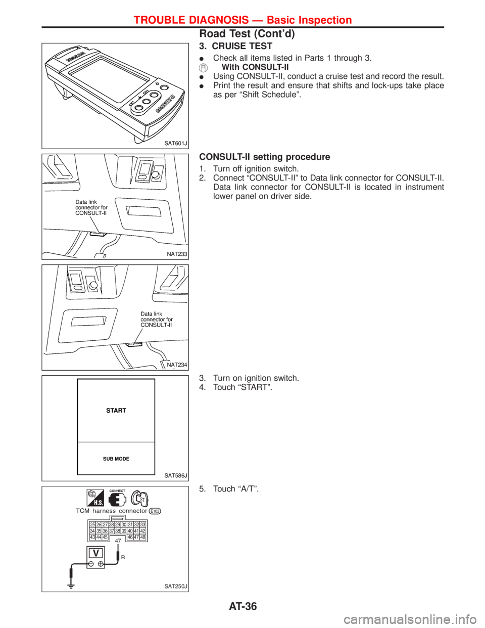
CONSULT-II setting procedure
1. Turn off ignition switch.
2. Connect ªCONSULT-IIº to Data link connector for CONSULT-II.
Data link connector for CONSULT-II is located in instrument
lower panel on driver side.
3. Turn on ignition switch.
4. Touch ªSTARTº.
5. Touch ªA/Tº.
SAT601J
NAT233
NAT234
SAT586J
SAT250J
TROUBLE DIAGNOSIS Ð Basic Inspection
Road Test (Cont'd)
AT-36
Page 289 of 1767
BODY & TRIM
SECTION
BT
CONTENTS
PRECAUTIONS...............................................................2
Service Notice..............................................................2
Supplemental Restraint System (SRS)²AIR
BAG²and²SEAT BELT PRE-TENSIONER²...............2
CLIP AND FASTENER....................................................3
Description ...................................................................3
CHASSIS AND BODY MAINTENANCE.........................5
Checking Body Corrosion ............................................5
BODY FRONT END.........................................................6
Removal and Installation .............................................6
BODY REAR END AND OPENER..................................8
Removal and Installation .............................................8
DOOR.............................................................................10
Removal and Installation ...........................................10
INSTRUMENT PANEL ASSEMBLY..............................16
Removal and Installation ...........................................16
SIDE AND FLOOR TRIM..............................................18
Removal and Installation ...........................................18
DOOR TRIM...................................................................19
Removal and Installation ...........................................19ROOF TRIM...................................................................20
Removal and Installation ...........................................20
EXTERIOR.....................................................................21
Removal and Installation ...........................................21
FRONT SEAT.................................................................34
Removal and Installation ...........................................34
Heated Seat ...............................................................36
Active Head Restraint ................................................36
SECOND SEAT..............................................................37
Removal and Installation ...........................................37
THIRD SEAT..................................................................39
Removal and Installation ...........................................39
SUNROOF......................................................................40
Removal and Installation ...........................................40
WINDSHIELD AND WINDOWS....................................42
Removal and Installation ...........................................42
DOOR MIRROR.............................................................48
Removal and Installation ...........................................48
BODY (ALIGNMENT)....................................................49
Alignment ...................................................................49
Page 290 of 1767
Service Notice
IWhen removing or installing various parts, place a cloth or padding onto the vehicle body to prevent
scratches.
IHandle trim, molding, instruments, grille, etc. carefully during removing or installing. Be careful not to oil
or damage them.
IApply sealing compound where necessary when installing parts.
IWhen applying sealing compound, be careful that the sealing compound does not protrude from parts.
IWhen replacing any metal parts (for example body outer panel, members, etc.), be sure to take rust pre-
vention measures.
Supplemental Restraint System (SRS) ªAIR
BAGº and ªSEAT BELT PRE-TENSIONERº
The Supplemental Restraint System such as ªAIR BAGº and ªSEAT BELT PRE-TENSIONERº used along with
a seat belt, helps to reduce the risk or severity of injury to the driver and front passenger for certain types of
collision. The SRS system composition which is available to NISSAN MODEL R20 is as follows (The compo-
sition varies according to the destination and optional equipment.):
IFor a frontal collision
The Supplemental Restraint System consists of driver air bag module (located in the center of the steer-
ing wheel), front passenger air bag module (located on the instrument panel on passenger side), front seat
belt pre-tensioners, a diagnosis sensor unit, warning lamp, wiring harness and spiral cable.
IFor a side collision
The Supplemental Restraint System consists of front side air bag module (located in the outer side of front
seat), side air bag (satellite) sensor, diagnosis sensor unit (one of components of air bags for a frontal
collision), wiring harness, warning lamp (one of components of air bags for a frontal collision).
Information necessary to service the system safely is included in theRSsection of this Service Manual.
WARNING:
ITo avoid rendering the SRS inoperative, which could increase the risk of personal injury or death
in the event of a collision which would result in air bag inflation, all maintenance should be per-
formed by an authorized NISSAN dealer.
IImproper maintenance, including incorrect removal and installation of the SRS, can lead to per-
sonal injury caused by unintentional activation of the system. For removal of Spiral Cable and Air
Bag Module, see the RS section.
IDo not use electrical test equipment on any circuit related to the SRS unless instructed to in this
Service Manual. Spiral cable and wiring harnesses covered with yellow insulation tape either just
before the harness connectors or for the complete harness are related to the SRS.
PRECAUTIONS
BT-2
Page 304 of 1767
Removal and Installation
CAUTION:
IDisconnect ground terminal from battery in advance.
IDisconnect air bag system line in advance.
INever tamper with or force air bag lid open, as this may adversely affect air bag performance.
IBe careful not to scratch pad and other parts.
INSTRUMENT PANEL ASSEMBLY
BT-16
Page 305 of 1767

NBF367
INSTRUMENT PANEL ASSEMBLY
Removal and Installation (Cont'd)
BT-17
Page 381 of 1767
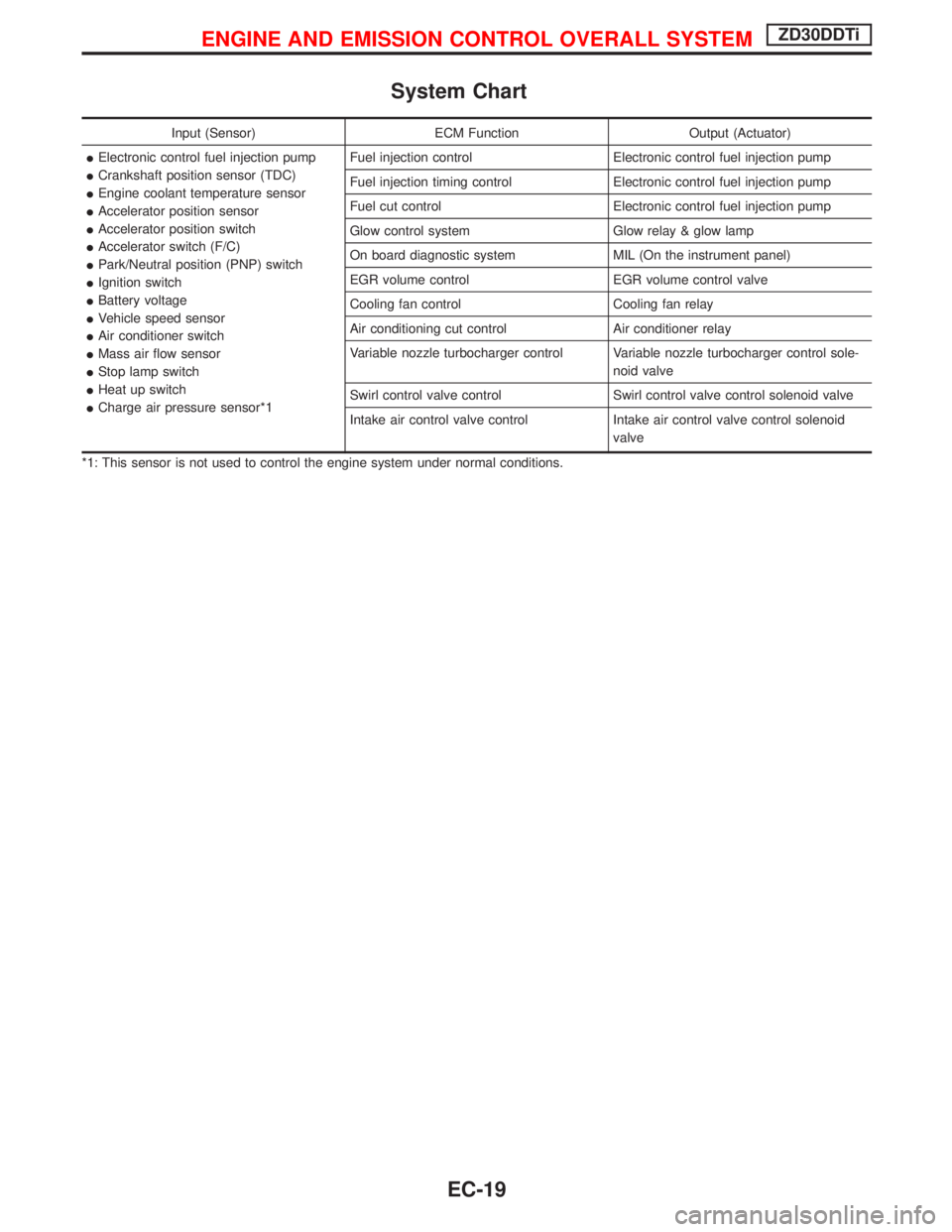
System Chart
Input (Sensor) ECM Function Output (Actuator)
IElectronic control fuel injection pump
ICrankshaft position sensor (TDC)
IEngine coolant temperature sensor
IAccelerator position sensor
IAccelerator position switch
IAccelerator switch (F/C)
IPark/Neutral position (PNP) switch
IIgnition switch
IBattery voltage
IVehicle speed sensor
IAir conditioner switch
IMass air flow sensor
IStop lamp switch
IHeat up switch
ICharge air pressure sensor*1Fuel injection control Electronic control fuel injection pump
Fuel injection timing control Electronic control fuel injection pump
Fuel cut control Electronic control fuel injection pump
Glow control system Glow relay & glow lamp
On board diagnostic system MIL (On the instrument panel)
EGR volume control EGR volume control valve
Cooling fan control Cooling fan relay
Air conditioning cut control Air conditioner relay
Variable nozzle turbocharger control Variable nozzle turbocharger control sole-
noid valve
Swirl control valve control Swirl control valve control solenoid valve
Intake air control valve control Intake air control valve control solenoid
valve
*1: This sensor is not used to control the engine system under normal conditions.
ENGINE AND EMISSION CONTROL OVERALL SYSTEMZD30DDTi
EC-19
Page 396 of 1767
IIf the battery is disconnected, the emission-related diagnostic information will be lost after approx.
24 hours.
IErasing the emission-related diagnostic information using CONSULT-II is easier and quicker than
switching the diagnostic test mode using the data link connector.
NATS (Nissan Anti-Theft System)
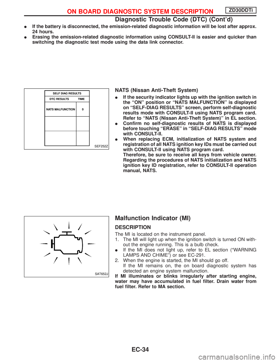
IIf the security indicator lights up with the ignition switch in
the ªONº position or ªNATS MALFUNCTIONº is displayed
on ªSELF-DIAG RESULTSº screen, perform self-diagnostic
results mode with CONSULT-II using NATS program card.
Refer to ªNATS (Nissan Anti-Theft System)º in EL section.
IConfirm no self-diagnostic results of NATS is displayed
before touching ªERASEº in ªSELF-DIAG RESULTSº mode
with CONSULT-II.
IWhen replacing ECM, initialization of NATS system and
registration of all NATS ignition key IDs must be carried out
with CONSULT-II using NATS program card.
Therefore, be sure to receive all keys from vehicle owner.
Regarding the procedures of NATS initialization and NATS
ignition key ID registration, refer to CONSULT-II operation
manual, NATS.
Malfunction Indicator (MI)
DESCRIPTION
The MI is located on the instrument panel.
1. The MI will light up when the ignition switch is turned ON with-
out the engine running. This is a bulb check.
IIf the MI does not light up, refer to EL section (ªWARNING
LAMPS AND CHIMEº) or see EC-291.
2. When the engine is started, the MI should go off.
If the MI remains on, the on board diagnostic system has
detected an engine system malfunction.
If MI illuminates or blinks irregularly after starting engine,
water may have accumulated in fuel filter. Drain water from
fuel filter. Refer to MA section.
SEF252Z
SAT652J
ON BOARD DIAGNOSTIC SYSTEM DESCRIPTIONZD30DDTi
Diagnostic Trouble Code (DTC) (Cont'd)
EC-34