Page 924 of 1767
YEL121D
REAR WINDOW DEFOGGER AND DOOR MIRROR DEFOGGER
Wiring Diagram Ð DEF Ð (Cont'd)
EL-108
Page 925 of 1767
Filament Check
1. Attach probe circuit tester (in volt range) to middle portion of
each filament.
6 volts = Normal filament
2. If a filament is burned out, circuit tester registers 0 or 12 volts.
3. To locate burned out point, move probe to left and right along
filament to determine point where tester needle swings
abruptly.
IWhen measuring voltage, wind a piece of tin foil around
the top of the negative probe and press the foil against the
wire with your finger.
SEL263
SEL265
SEL266
YEL553D
REAR WINDOW DEFOGGER AND DOOR MIRROR DEFOGGER
EL-109
Page 926 of 1767

Filament Repair
REPAIR EQUIPMENT
1. Conductive silver composition (Dupont No. 4817 or equivalent)
2. Ruler 30 cm (11.8 in) long
3. Drawing pen
4. Heat gun
5. Alcohol
6. Cloth
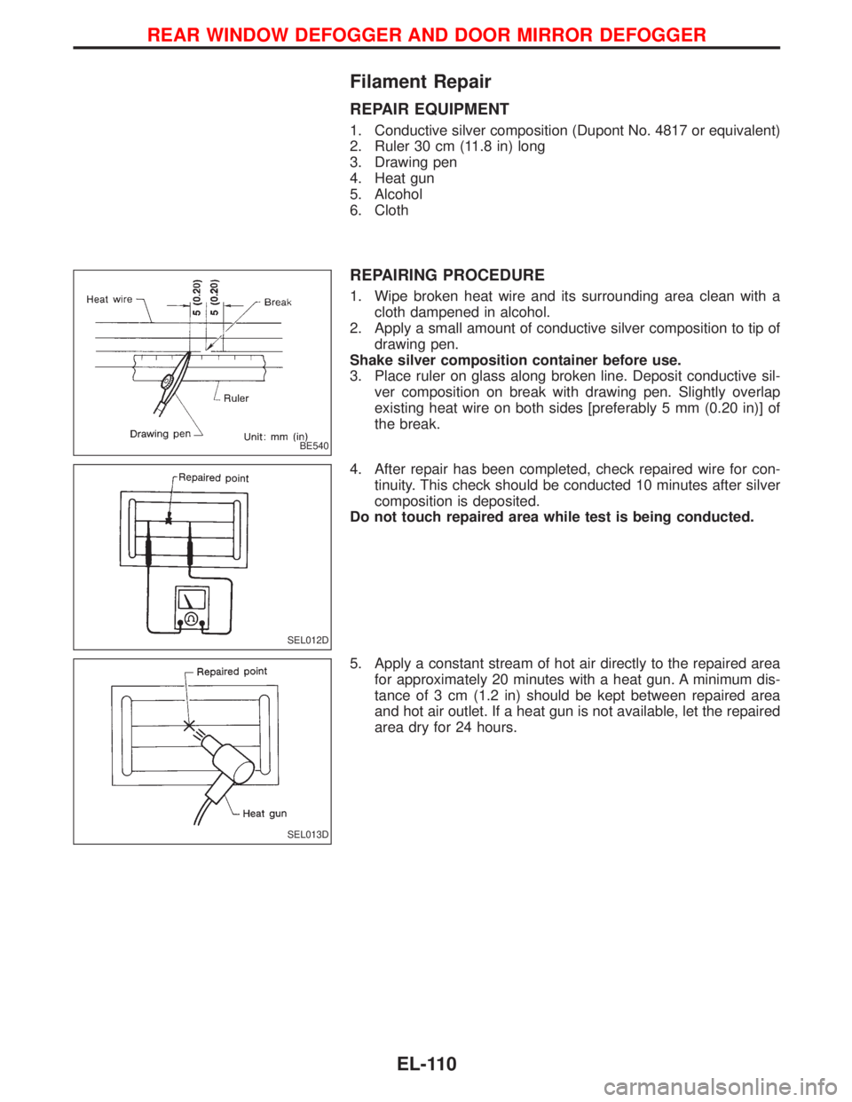
REPAIRING PROCEDURE
1. Wipe broken heat wire and its surrounding area clean with a
cloth dampened in alcohol.
2. Apply a small amount of conductive silver composition to tip of
drawing pen.
Shake silver composition container before use.
3. Place ruler on glass along broken line. Deposit conductive sil-
ver composition on break with drawing pen. Slightly overlap
existing heat wire on both sides [preferably 5 mm (0.20 in)] of
the break.
4. After repair has been completed, check repaired wire for con-
tinuity. This check should be conducted 10 minutes after silver
composition is deposited.
Do not touch repaired area while test is being conducted.
5. Apply a constant stream of hot air directly to the repaired area
for approximately 20 minutes with a heat gun. A minimum dis-
tance of 3 cm (1.2 in) should be kept between repaired area
and hot air outlet. If a heat gun is not available, let the repaired
area dry for 24 hours.
BE540
SEL012D
SEL013D
REAR WINDOW DEFOGGER AND DOOR MIRROR DEFOGGER
EL-110
Page 947 of 1767
Wiring Diagram Ð MIRROR Ð
LHD MODELS
YEL136D
DOOR MIRROR
EL-131
Page 948 of 1767
RHD MODELS
YEL137D
DOOR MIRROR
Wiring Diagram Ð MIRROR Ð (Cont'd)
EL-132
Page 996 of 1767

System Description
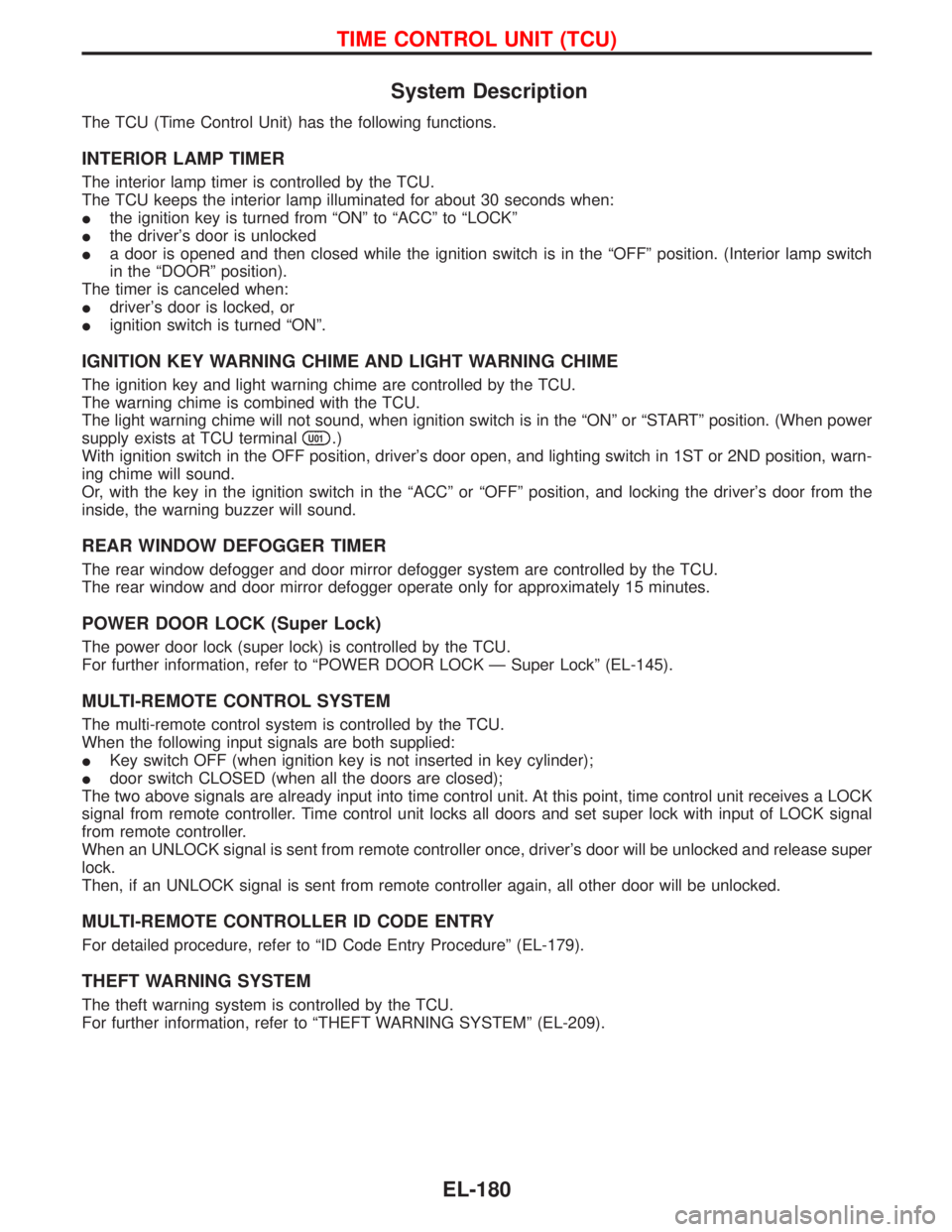
The TCU (Time Control Unit) has the following functions.
INTERIOR LAMP TIMER
The interior lamp timer is controlled by the TCU.
The TCU keeps the interior lamp illuminated for about 30 seconds when:
Ithe ignition key is turned from ªONº to ªACCº to ªLOCKº
Ithe driver's door is unlocked
Ia door is opened and then closed while the ignition switch is in the ªOFFº position. (Interior lamp switch
in the ªDOORº position).
The timer is canceled when:
Idriver's door is locked, or
Iignition switch is turned ªONº.
IGNITION KEY WARNING CHIME AND LIGHT WARNING CHIME
The ignition key and light warning chime are controlled by the TCU.
The warning chime is combined with the TCU.
The light warning chime will not sound, when ignition switch is in the ªONº or ªSTARTº position. (When power
supply exists at TCU terminal
U01.)
With ignition switch in the OFF position, driver's door open, and lighting switch in 1ST or 2ND position, warn-
ing chime will sound.
Or, with the key in the ignition switch in the ªACCº or ªOFFº position, and locking the driver's door from the
inside, the warning buzzer will sound.
REAR WINDOW DEFOGGER TIMER
The rear window defogger and door mirror defogger system are controlled by the TCU.
The rear window and door mirror defogger operate only for approximately 15 minutes.
POWER DOOR LOCK (Super Lock)
The power door lock (super lock) is controlled by the TCU.
For further information, refer to ªPOWER DOOR LOCK Ð Super Lockº (EL-145).
MULTI-REMOTE CONTROL SYSTEM
The multi-remote control system is controlled by the TCU.
When the following input signals are both supplied:
IKey switch OFF (when ignition key is not inserted in key cylinder);
Idoor switch CLOSED (when all the doors are closed);
The two above signals are already input into time control unit. At this point, time control unit receives a LOCK
signal from remote controller. Time control unit locks all doors and set super lock with input of LOCK signal
from remote controller.
When an UNLOCK signal is sent from remote controller once, driver's door will be unlocked and release super
lock.
Then, if an UNLOCK signal is sent from remote controller again, all other door will be unlocked.
MULTI-REMOTE CONTROLLER ID CODE ENTRY
For detailed procedure, refer to ªID Code Entry Procedureº (EL-179).
THEFT WARNING SYSTEM
The theft warning system is controlled by the TCU.
For further information, refer to ªTHEFT WARNING SYSTEMº (EL-209).
TIME CONTROL UNIT (TCU)
EL-180
Page 997 of 1767

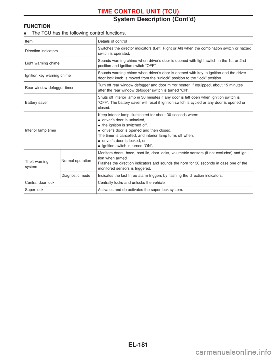
FUNCTION
IThe TCU has the following control functions.
Item Details of control
Direction indicatorsSwitches the director indicators (Left, Right or All) when the combination switch or hazard
switch is operated.
Light warning chimeSounds warning chime when driver's door is opened with light switch in the 1st or 2nd
position and ignition switch ªOFFº.
Ignition key warning chimeSounds warning chime when driver's door is opened with key in ignition and the driver
door lock knob is moved from the ªunlockº position to the ªlockº position.
Rear window defogger timerTurn off rear window defogger and door mirror heater, if equipped, about 15 minutes
after the rear window defogger switch is turned ªONº.
Battery saverShuts off interior lamp in 30 minutes if any door is left open when ignition switch is
ªOFFº. The battery saver will reset if ignition switch is cycled or any door is opened or
closed.
Interior lamp timerKeep interior lamp illuminated for about 30 seconds when:
Idriver's door is unlocked,
Ithe ignition is switched off,
Idriver's door is opened and then closed.
The timer is cancelled, and interior lamp turns off when:
Idriver's door is locked, or
Iignition switch is turned ªONº.
Theft warning
systemNormal operationMonitors doors, hood, boot lid, door locks, volumetric sensors (if not excluded) and igni-
tion when armed.
Flashes the direction indicators and sounds the horn for 30 seconds in case one of the
monitored sensors is triggered.
Diagnostic mode Indicates the last three alarm triggers by flashing the direction indicators.
Central door lock Centrally locks and unlocks the vehicle
Super lock Activates and de-activates the super lock system.
TIME CONTROL UNIT (TCU)
System Description (Cont'd)
EL-181
Page 1107 of 1767

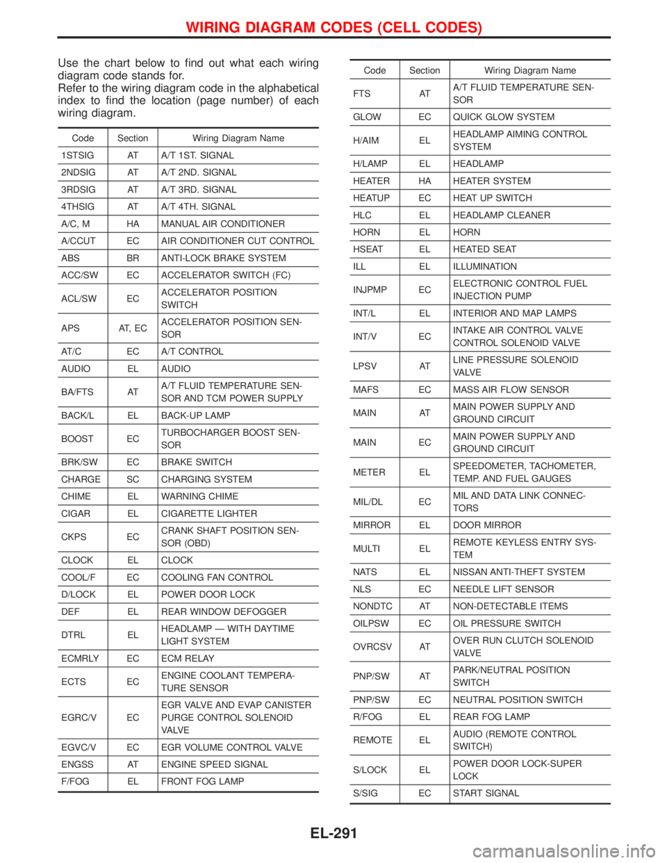
Use the chart below to find out what each wiring
diagram code stands for.
Refer to the wiring diagram code in the alphabetical
index to find the location (page number) of each
wiring diagram.
Code Section Wiring Diagram Name
1STSIG AT A/T 1ST. SIGNAL
2NDSIG AT A/T 2ND. SIGNAL
3RDSIG AT A/T 3RD. SIGNAL
4THSIG AT A/T 4TH. SIGNAL
A/C, M HA MANUAL AIR CONDITIONER
A/CCUT EC AIR CONDITIONER CUT CONTROL
ABS BR ANTI-LOCK BRAKE SYSTEM
ACC/SW EC ACCELERATOR SWITCH (FC)
ACL/SW ECACCELERATOR POSITION
SWITCH
APS AT, ECACCELERATOR POSITION SEN-
SOR
AT/C EC A/T CONTROL
AUDIO EL AUDIO
BA/FTS ATA/T FLUID TEMPERATURE SEN-
SOR AND TCM POWER SUPPLY
BACK/L EL BACK-UP LAMP
BOOST ECTURBOCHARGER BOOST SEN-
SOR
BRK/SW EC BRAKE SWITCH
CHARGE SC CHARGING SYSTEM
CHIME EL WARNING CHIME
CIGAR EL CIGARETTE LIGHTER
CKPS ECCRANK SHAFT POSITION SEN-
SOR (OBD)
CLOCK EL CLOCK
COOL/F EC COOLING FAN CONTROL
D/LOCK EL POWER DOOR LOCK
DEF EL REAR WINDOW DEFOGGER
DTRL ELHEADLAMP Ð WITH DAYTIME
LIGHT SYSTEM
ECMRLY EC ECM RELAY
ECTS ECENGINE COOLANT TEMPERA-
TURE SENSOR
EGRC/V ECEGR VALVE AND EVAP CANISTER
PURGE CONTROL SOLENOID
VA LV E
EGVC/V EC EGR VOLUME CONTROL VALVE
ENGSS AT ENGINE SPEED SIGNAL
F/FOG EL FRONT FOG LAMP
Code Section Wiring Diagram Name
FTS ATA/T FLUID TEMPERATURE SEN-
SOR
GLOW EC QUICK GLOW SYSTEM
H/AIM ELHEADLAMP AIMING CONTROL
SYSTEM
H/LAMP EL HEADLAMP
HEATER HA HEATER SYSTEM
HEATUP EC HEAT UP SWITCH
HLC EL HEADLAMP CLEANER
HORN EL HORN
HSEAT EL HEATED SEAT
ILL EL ILLUMINATION
INJPMP ECELECTRONIC CONTROL FUEL
INJECTION PUMP
INT/L EL INTERIOR AND MAP LAMPS
INT/V ECINTAKE AIR CONTROL VALVE
CONTROL SOLENOID VALVE
LPSV ATLINE PRESSURE SOLENOID
VA LV E
MAFS EC MASS AIR FLOW SENSOR
MAIN ATMAIN POWER SUPPLY AND
GROUND CIRCUIT
MAIN ECMAIN POWER SUPPLY AND
GROUND CIRCUIT
METER ELSPEEDOMETER, TACHOMETER,
TEMP. AND FUEL GAUGES
MIL/DL ECMIL AND DATA LINK CONNEC-
TORS
MIRROR EL DOOR MIRROR
MULTI ELREMOTE KEYLESS ENTRY SYS-
TEM
NATS EL NISSAN ANTI-THEFT SYSTEM
NLS EC NEEDLE LIFT SENSOR
NONDTC AT NON-DETECTABLE ITEMS
OILPSW EC OIL PRESSURE SWITCH
OVRCSV ATOVER RUN CLUTCH SOLENOID
VA LV E
PNP/SW ATPARK/NEUTRAL POSITION
SWITCH
PNP/SW EC NEUTRAL POSITION SWITCH
R/FOG EL REAR FOG LAMP
REMOTE ELAUDIO (REMOTE CONTROL
SWITCH)
S/LOCK ELPOWER DOOR LOCK-SUPER
LOCK
S/SIG EC START SIGNAL
WIRING DIAGRAM CODES (CELL CODES)
EL-291