2002 NISSAN TERRANO automatic transmission fluid
[x] Cancel search: automatic transmission fluidPage 3 of 1767
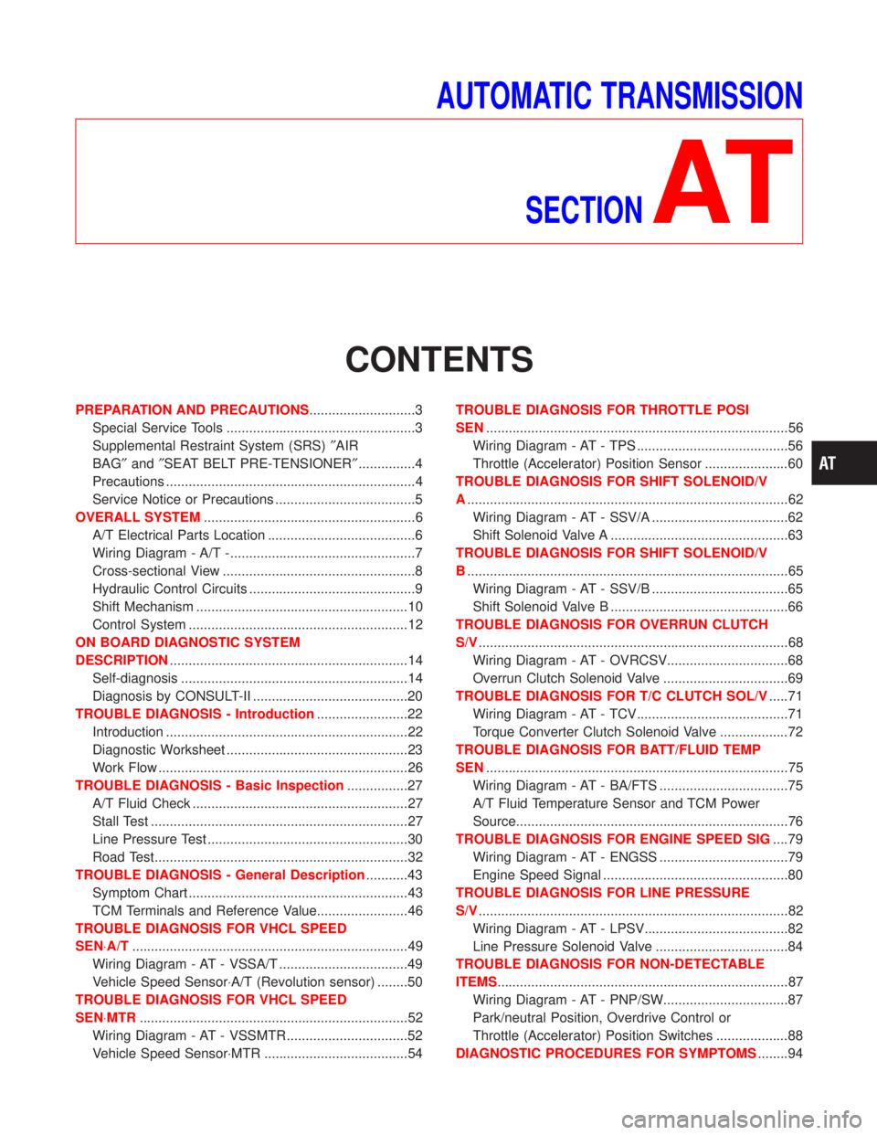
AUTOMATIC TRANSMISSION
SECTION
AT
CONTENTS
PREPARATION AND PRECAUTIONS............................3
Special Service Tools ..................................................3
Supplemental Restraint System (SRS)²AIR
BAG²and²SEAT BELT PRE-TENSIONER²...............4
Precautions ..................................................................4
Service Notice or Precautions .....................................5
OVERALL SYSTEM........................................................6
A/T Electrical Parts Location .......................................6
Wiring Diagram - A/T -.................................................7
Cross-sectional View ...................................................8
Hydraulic Control Circuits ............................................9
Shift Mechanism ........................................................10
Control System ..........................................................12
ON BOARD DIAGNOSTIC SYSTEM
DESCRIPTION...............................................................14
Self-diagnosis ............................................................14
Diagnosis by CONSULT-II .........................................20
TROUBLE DIAGNOSIS - Introduction........................22
Introduction ................................................................22
Diagnostic Worksheet ................................................23
Work Flow ..................................................................26
TROUBLE DIAGNOSIS - Basic Inspection................27
A/T Fluid Check .........................................................27
Stall Test ....................................................................27
Line Pressure Test .....................................................30
Road Test...................................................................32
TROUBLE DIAGNOSIS - General Description...........43
Symptom Chart ..........................................................43
TCM Terminals and Reference Value........................46
TROUBLE DIAGNOSIS FOR VHCL SPEED
SEN×A/T.........................................................................49
Wiring Diagram - AT - VSSA/T ..................................49
Vehicle Speed Sensor×A/T (Revolution sensor) ........50
TROUBLE DIAGNOSIS FOR VHCL SPEED
SEN×MTR.......................................................................52
Wiring Diagram - AT - VSSMTR ................................52
Vehicle Speed Sensor×MTR ......................................54TROUBLE DIAGNOSIS FOR THROTTLE POSI
SEN................................................................................56
Wiring Diagram - AT - TPS ........................................56
Throttle (Accelerator) Position Sensor ......................60
TROUBLE DIAGNOSIS FOR SHIFT SOLENOID/V
A.....................................................................................62
Wiring Diagram - AT - SSV/A ....................................62
Shift Solenoid Valve A ...............................................63
TROUBLE DIAGNOSIS FOR SHIFT SOLENOID/V
B.....................................................................................65
Wiring Diagram - AT - SSV/B ....................................65
Shift Solenoid Valve B ...............................................66
TROUBLE DIAGNOSIS FOR OVERRUN CLUTCH
S/V..................................................................................68
Wiring Diagram - AT - OVRCSV................................68
Overrun Clutch Solenoid Valve .................................69
TROUBLE DIAGNOSIS FOR T/C CLUTCH SOL/V.....71
Wiring Diagram - AT - TCV........................................71
Torque Converter Clutch Solenoid Valve ..................72
TROUBLE DIAGNOSIS FOR BATT/FLUID TEMP
SEN................................................................................75
Wiring Diagram - AT - BA/FTS ..................................75
A/T Fluid Temperature Sensor and TCM Power
Source........................................................................76
TROUBLE DIAGNOSIS FOR ENGINE SPEED SIG....79
Wiring Diagram - AT - ENGSS ..................................79
Engine Speed Signal .................................................80
TROUBLE DIAGNOSIS FOR LINE PRESSURE
S/V..................................................................................82
Wiring Diagram - AT - LPSV......................................82
Line Pressure Solenoid Valve ...................................84
TROUBLE DIAGNOSIS FOR NON-DETECTABLE
ITEMS.............................................................................87
Wiring Diagram - AT - PNP/SW.................................87
Park/neutral Position, Overdrive Control or
Throttle (Accelerator) Position Switches ...................88
DIAGNOSTIC PROCEDURES FOR SYMPTOMS........94
Page 14 of 1767
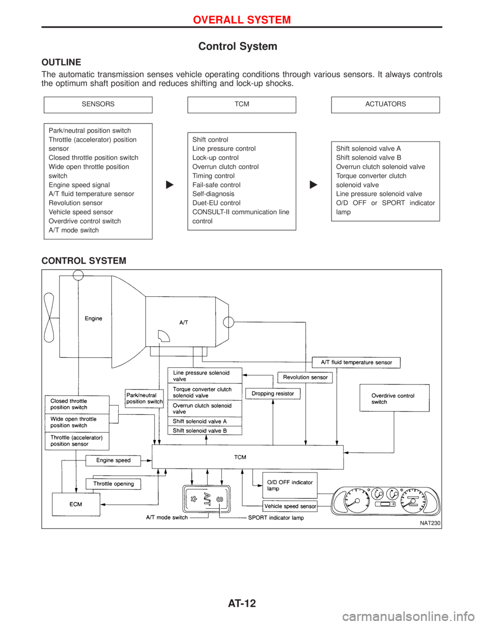
Control System
OUTLINE
The automatic transmission senses vehicle operating conditions through various sensors. It always controls
the optimum shaft position and reduces shifting and lock-up shocks.
SENSORSTCMACTUATORS
Park/neutral position switch
Throttle (accelerator) position
sensor
Closed throttle position switch
Wide open throttle position
switch
Engine speed signal
A/T fluid temperature sensor
Revolution sensor
Vehicle speed sensor
Overdrive control switch
A/T mode switch
E
Shift control
Line pressure control
Lock-up control
Overrun clutch control
Timing control
Fail-safe control
Self-diagnosis
Duet-EU control
CONSULT-II communication line
control
E
Shift solenoid valve A
Shift solenoid valve B
Overrun clutch solenoid valve
Torque converter clutch
solenoid valve
Line pressure solenoid valve
O/D OFF or SPORT indicator
lamp
CONTROL SYSTEM
NAT230
OVERALL SYSTEM
AT-12
Page 198 of 1767
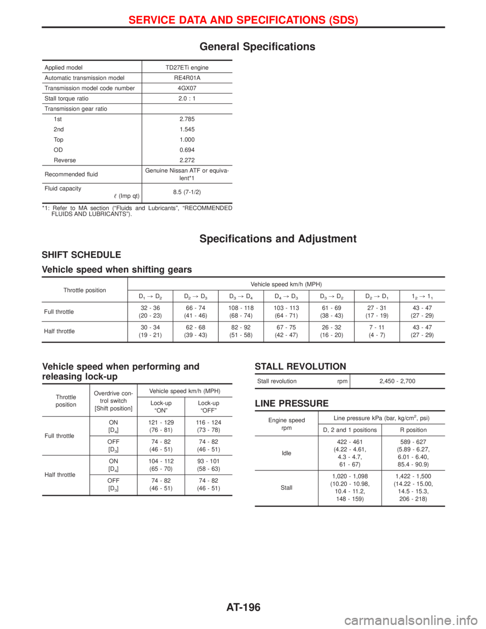
General Specifications
Applied model TD27ETi engine
Automatic transmission model RE4R01A
Transmission model code number 4GX07
Stall torque ratio 2.0 : 1
Transmission gear ratio
1st 2.785
2nd 1.545
Top 1.000
OD 0.694
Reverse 2.272
Recommended fluidGenuine Nissan ATF or equiva-
lent*1
Fluid capacity
(Imp qt)8.5 (7-1/2)
*1: Refer to MA section (ªFluids and Lubricantsº, ªRECOMMENDED
FLUIDS AND LUBRICANTSº).
Specifications and Adjustment
SHIFT SCHEDULE
Vehicle speed when shifting gears
Throttle positionVehicle speed km/h (MPH)
D1,D2D2,D3D3,D4D4,D3D3,D2D2,D112,11
Full throttle32-36
(20 - 23)66-74
(41 - 46)108 - 118
(68 - 74)103 - 113
(64 - 71)61-69
(38 - 43)27-31
(17 - 19)43-47
(27 - 29)
Half throttle30-34
(19 - 21)62-68
(39 - 43)82-92
(51 - 58)67-75
(42 - 47)26-32
(16 - 20)7-11
(4-7)43-47
(27 - 29)
Vehicle speed when performing and
releasing lock-up
Throttle
positionOverdrive con-
trol switch
[Shift position]Vehicle speed km/h (MPH)
Lock-up
ªONºLock-up
ªOFFº
Full throttleON
[D
4]121 - 129
(76 - 81)116 - 124
(73 - 78)
OFF
[D
3]74-82
(46 - 51)74-82
(46 - 51)
Half throttleON
[D
4]104 - 112
(65 - 70)93 - 101
(58 - 63)
OFF
[D
3]74-82
(46 - 51)74-82
(46 - 51)
STALL REVOLUTION
Stall revolution rpm 2,450 - 2,700
LINE PRESSURE
Engine speed
rpmLine pressure kPa (bar, kg/cm2, psi)
D, 2 and 1 positions R position
Idle422 - 461
(4.22 - 4.61,
4.3 - 4.7,
61 - 67)589 - 627
(5.89 - 6.27,
6.01 - 6.40,
85.4 - 90.9)
Stall1,020 - 1,098
(10.20 - 10.98,
10.4 - 11.2,
148 - 159)1,422 - 1,500
(14.22 - 15.00,
14.5 - 15.3,
206 - 218)
SERVICE DATA AND SPECIFICATIONS (SDS)
AT-196
Page 1324 of 1767
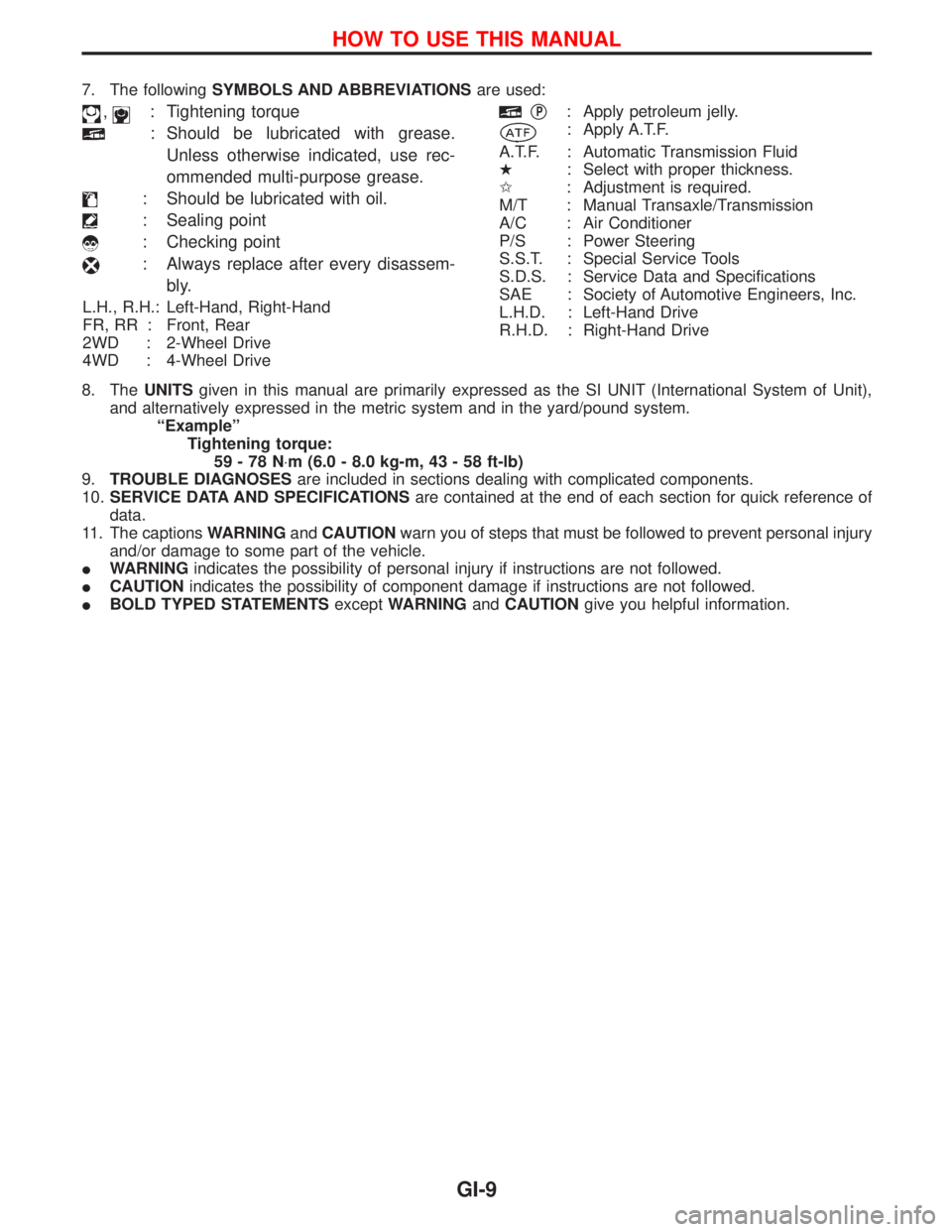
7. The followingSYMBOLS AND ABBREVIATIONSare used:
,: Tightening torque
: Should be lubricated with grease.
Unless otherwise indicated, use rec-
ommended multi-purpose grease.
: Should be lubricated with oil.
: Sealing point
: Checking point
: Always replace after every disassem-
bly.
L.H., R.H.: Left-Hand, Right-Hand
FR, RR : Front, Rear
2WD : 2-Wheel Drive
4WD : 4-Wheel Drive
qP: Apply petroleum jelly.
: Apply A.T.F.
A.T.F. : Automatic Transmission Fluid
H: Select with proper thickness.
I: Adjustment is required.
M/T : Manual Transaxle/Transmission
A/C : Air Conditioner
P/S : Power Steering
S.S.T. : Special Service Tools
S.D.S. : Service Data and Specifications
SAE : Society of Automotive Engineers, Inc.
L.H.D. : Left-Hand Drive
R.H.D. : Right-Hand Drive
8. TheUNITSgiven in this manual are primarily expressed as the SI UNIT (International System of Unit),
and alternatively expressed in the metric system and in the yard/pound system.
ªExampleº
Tightening torque:
59-78N×m (6.0 - 8.0 kg-m, 43 - 58 ft-lb)
9.TROUBLE DIAGNOSESare included in sections dealing with complicated components.
10.SERVICE DATA AND SPECIFICATIONSare contained at the end of each section for quick reference of
data.
11. The captionsWARNINGandCAUTIONwarn you of steps that must be followed to prevent personal injury
and/or damage to some part of the vehicle.
IWARNINGindicates the possibility of personal injury if instructions are not followed.
ICAUTIONindicates the possibility of component damage if instructions are not followed.
IBOLD TYPED STATEMENTSexceptWARNINGandCAUTIONgive you helpful information.
HOW TO USE THIS MANUAL
GI-9
Page 1419 of 1767
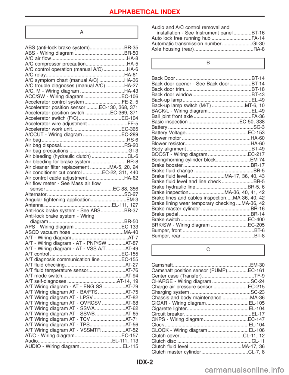
A
ABS (anti-lock brake system).........................BR-35
ABS - Wiring diagram ....................................BR-50
A/C air flow .......................................................HA-8
A/C compressor precaution..............................HA-5
A/C control operation (manual A/C) .................HA-6
A/C relay.........................................................HA-61
A/C symptom chart (manual A/C) ..................HA-36
A/C trouble diagnoses (manual A/C) .............HA-27
A/C, M - Wiring diagram ................................HA-43
ACC/SW - Wiring diagram ...........................EC-106
Accelerator control system ...........................FE-2, 5
Accelerator position sensor .........EC-130, 368, 371
Accelerator position switch ..................EC-369, 371
Accelerator switch (F/C) ...............................EC-104
Accelerator wire adjustment .............................FE-5
Accelerator work unit....................................EC-365
A/CCUT - Wiring diagram ............................EC-289
Air bag ..............................................................RS-6
Air bag disposal..............................................RS-20
Air bag precautions ...........................................GI-3
Air bleeding (hydraulic clutch) ..........................CL-6
Air bleeding for brake system ..........................BR-8
Air cleaner filter replacement ..............MA-5, 20, 24
Air conditioner cut control ..............EC-22, 311, 440
Air control cable adjustment...........................HA-62
Air flow meter - See Mass air flow
sensor .................................................EC-88, 356
Alternator ........................................................SC-27
Angular tightening application..........................EM-3
Antenna .................................................EL-111, 127
Anti-lock brake system - See ABS .................BR-37
Anti-lock brake system - Wiring
diagram .......................................................BR-50
APS - Wiring diagram ..................................EC-133
ASCD vacuum hose ......................................MA-40
A/T - Wiring diagram .........................................AT-7
A/T - Wiring diagram - AT - PNP/SW .............AT-87
A/T - Wiring diagram - AT - VSS A/T ..............AT-49
A/T control ....................................................EC-155
A/T diagnosis communication line ...............EC-155
A/T fluid checking ............................................AT-27
A/T fluid temperature sensor...........................AT-76
A/T mode switch..............................................AT-94
A/T self-diagnoses ....................................AT-14, 19
A/T Wiring diagram - AT - ENG SS ................AT-79
A/T Wiring diagram AT - BA/FTS ....................AT-75
A/T Wiring diagram AT - LPSV .......................AT-82
A/T Wiring diagram AT - OVRCSV .................AT-68
A/T Wiring diagram AT - SSV/A ......................AT-62
A/T Wiring diagram AT - SSV/B ......................AT-65
A/T Wiring diagram AT - TCV .........................AT-71
A/T Wiring diagram AT - TPS..........................AT-56
A/T Wiring diagram AT - VSSMTR .................AT-52
AT/C - Wiring diagram..................................EC-157
Audio......................................................EL-111, 113
AUDIO - Wiring diagram ...............................EL-115Audio and A/C control removal and
installation - See Instrument panel .............BT-16
Auto lock free running hub .............................FA-14
Automatic transmission number ......................GI-30
Axle housing (rear) ...........................................RA-8
B
Back Door .......................................................BT-14
Back door opener - See Back door ................BT-14
Back door trim.................................................BT-18
Back door window...........................................BT-43
Back-up lamp ..................................................EL-49
Back-up lamp switch (M/T) ........................MT-6, 10
BACK/L - Wiring diagram................................EL-49
Ball joint front axle ..........................................FA-36
Basic inspection .....................................EC-50, 338
Battery ..............................................................SC-3
Battery Voltage .............................................EC-153
Blower motor ..................................................HA-60
Blower resistor................................................HA-60
Body alignment ...............................................BT-49
BOOST - Wiring diagram .............................EC-217
Boring/horning cylinder block.........................EM-74
Brake booster .................................................BR-17
Brake fluid change ...........................................BR-5
Brake fluid level ...........................MA-17, 36, 40, 43
Brake fluid level and line check .......................BR-5
Brake hydraulic line......................................BR-5, 6
Brake inspection ..........................MA-36, 40, 41, 42
Brake lines and cables inspection.....MA-36, 40, 42
Brake lining wear temporary checking ....MA-36, 42
Brake master cylinder ....................................BR-16
Brake pedal ....................................................BR-14
Brake switch .................................................EC-400
BRK/SW - Wiring diagram ...........................EC-205
Bumper, front ....................................................BT-6
Bumper, rear .....................................................BT-8
C
Camshaft ........................................................EM-30
Camshaft position sensor (PUMP)...............EC-161
Center case (Transfer) ......................................TF-9
CHARGE - Wiring diagram ............................SC-24
Charge air pressure sensor .........................EC-215
Charging system ............................................SC-23
Chassis and body maintenance ....................MA-36
CIGAR - Wiring diagram ...............................EL-105
Cigarette lighter.............................................EL-104
Circuit breaker.................................................EL-17
CKPS - Wiring diagram ................................EC-147
Clock .............................................................EL-104
CLOCK - Wiring diagram ..............................EL-106
Clutch cover ..............................................CL-11, 12
Clutch disc ......................................................CL-11
Clutch fluid level ......................................MA-17, 36
Clutch master cylinder ..................................CL-7, 8
ALPHABETICAL INDEX
IDX-2
Page 1471 of 1767
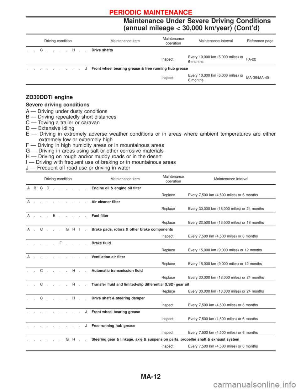
Driving condition Maintenance itemMaintenance
operationMaintenance interval Reference page
..C....H..Drive shafts
InspectEvery 10,000 km (6,000 miles) or
6 monthsFA-22
.........JFront wheel bearing grease & free running hub grease
InspectEvery 10,000 km (6,000 miles) or
6 monthsMA-39/MA-40
ZD30DDTi engine
Severe driving conditions
A Ð Driving under dusty conditions
B Ð Driving repeatedly short distances
C Ð Towing a trailer or caravan
D Ð Extensive idling
E Ð Driving in extremely adverse weather conditions or in areas where ambient temperatures are either
extremely low or extremely high
F Ð Driving in high humidity areas or in mountainous areas
G Ð Driving in areas using salt or other corrosive materials
H Ð Driving on rough and/or muddy roads or in the desert
I Ð Driving with frequent use of braking or in mountainous areas
J Ð Frequent off road use or driving in water
Driving condition Maintenance itemMaintenance
operationMaintenance interval
ABCD......Engine oil & engine oil filter
Replace Every 7,500 km (4,500 miles) or 6 months
A.........Air cleaner filter
Replace Every 30,000 km (18,000 miles) or 24 months
A...E.....Fuel filter
Replace Every 22,500 km (13,500 miles) or 18 months
A.C...GHI.Brake pads, rotors & other brake components
Inspect Every 7,500 km (4,500 miles) or 6 months
.....F....Brake fluid
Replace Every 15,000 km (9,000 miles) or 12 months
A.........Ventilation air filter
Replace Every 15,000 km (9,000 miles) or 12 months
..C....H..Automatic transmission fluid
Replace Every 30,000 km (18,000 miles) or 24 months
..C....H..Transfer fluid and limited-slip differential (LSD) gear oil
Replace Every 30,000 km (18,000 miles) or 24 months
..C....H..Drive shaft & steering damper
Inspect Every 7,500 km (4,500 miles) or 6 months
.........JFront wheel bearing grease
Inspect Every 7,500 km (4,500 miles) or 6 months
.........JFree-running hub grease
Inspect Every 7,500 km (4,500 miles) or 6 months
......GH..Steering gear & linkage, axle & suspension parts, propeller shaft & exhaust system
Inspect Every 7,500 km (4,500 miles) or 6 months
PERIODIC MAINTENANCE
Maintenance Under Severe Driving Conditions
(annual mileage < 30,000 km/year) (Cont'd)
MA-12
Page 1474 of 1767
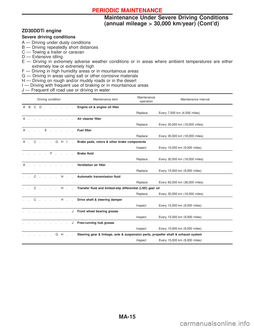
ZD30DDTi engine
Severe driving conditions
A Ð Driving under dusty conditions
B Ð Driving repeatedly short distances
C Ð Towing a trailer or caravan
D Ð Extensive idling
E Ð Driving in extremely adverse weather conditions or in areas where ambient temperatures are either
extremely low or extremely high
F Ð Driving in high humidity areas or in mountainous areas
G Ð Driving in areas using salt or other corrosive materials
H Ð Driving on rough and/or muddy roads or in the desert
I Ð Driving with frequent use of braking or in mountainous areas
J Ð Frequent off road use or driving in water
Driving condition Maintenance itemMaintenance
operationMaintenance interval
ABCD......Engine oil & engine oil filter
Replace Every 7,500 km (4,500 miles)
A.........Air cleaner filter
Replace Every 30,000 km (18,000 miles)
A...E.....Fuel filter
Replace Every 30,000 km (18,000 miles)
A.C...GHI.Brake pads, rotors & other brake components
Inspect Every 15,000 km (9,000 miles)
.....F....Brake fluid
Replace Every 30,000 km (18,000 miles)
A.........Ventilation air filter
Replace Every 15,000 km (9,000 miles)
..C....H..Automatic transmission fluid
Replace Every 60,000 km (36,000 miles)
..C....H..Transfer fluid and limited-slip differential (LSD) gear oil
Replace Every 30,000 km (18,000 miles)
..C....H..Drive shaft & steering damper
Inspect Every 15,000 km (9,000 miles)
.........JFront wheel bearing grease
Inspect Every 15,000 km (9,000 miles)
.........JFree-running hub grease
Inspect Every 15,000 km (9,000 miles)
......GH..Steering gear & linkage, axle & suspension parts, propeller shaft & exhaust system
Inspect Every 15,000 km (9,000 miles)
PERIODIC MAINTENANCE
Maintenance Under Severe Driving Conditions
(annual mileage > 30,000 km/year) (Cont'd)
MA-15
Page 1476 of 1767
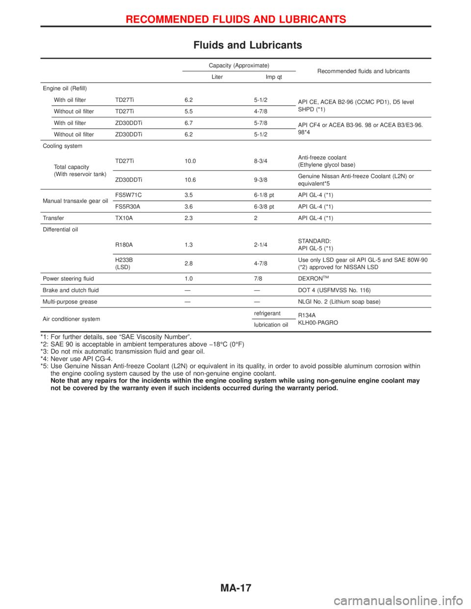
Fluids and Lubricants
Capacity (Approximate)
Recommended fluids and lubricants
Liter Imp qt
Engine oil (Refill)
With oil filter TD27Ti 6.2 5-1/2
API CE, ACEA B2-96 (CCMC PD1), D5 level
SHPD (*1)
Without oil filter TD27Ti 5.5 4-7/8
With oil filter ZD30DDTi 6.7 5-7/8
API CF4 or ACEA B3-96. 98 or ACEA B3/E3-96.
98*4
Without oil filter ZD30DDTi 6.2 5-1/2
Cooling system
Total capacity
(With reservoir tank)TD27Ti 10.0 8-3/4Anti-freeze coolant
(Ethylene glycol base)
ZD30DDTi 10.6 9-3/8Genuine Nissan Anti-freeze Coolant (L2N) or
equivalent*5
Manual transaxle gear oilFS5W71C 3.5 6-1/8 pt API GL-4 (*1)
FS5R30A 3.6 6-3/8 pt API GL-4 (*1)
Transfer TX10A 2.3 2 API GL-4 (*1)
Differential oil
R180A 1.3 2-1/4STANDARD:
API GL-5 (*1)
H233B
(LSD)2.8 4-7/8Use only LSD gear oil API GL-5 and SAE 80W-90
(*2) approved for NISSAN LSD
Power steering fluid 1.0 7/8 DEXRON
TM
Brake and clutch fluid Ð Ð DOT 4 (USFMVSS No. 116)
Multi-purpose grease Ð Ð NLGI No. 2 (Lithium soap base)
Air conditioner systemrefrigerant
R134A
KLH00-PAGRO
lubrication oil
*1: For further details, see ªSAE Viscosity Numberº.
*2: SAE 90 is acceptable in ambient temperatures above þ18ÉC (0ÉF)
*3: Do not mix automatic transmission fluid and gear oil.
*4: Never use API CG-4.
*5: Use Genuine Nissan Anti-freeze Coolant (L2N) or equivalent in its quality, in order to avoid possible aluminum corrosion within
the engine cooling system caused by the use of non-genuine engine coolant.
Note that any repairs for the incidents within the engine cooling system while using non-genuine engine coolant may
not be covered by the warranty even if such incidents occurred during the warranty period.
RECOMMENDED FLUIDS AND LUBRICANTS
MA-17