2002 NISSAN TERRANO Condition
[x] Cancel search: ConditionPage 1 of 1767

Edition: February 2002
Release: February 2002 (01)
Publication No.: SM2E00-1R20E0E
GENERAL INFORMATIONGI
MAINTENANCEMA
ENGINE MECHANICALEM
ENGINE LUBRICATION &
COOLING SYSTEMSLC
ENGINE CONTROL SYSTEMEC
ACCELERATOR CONTROL,
FUEL & EXHAUST SYSTEMFE
CLUTCHCL
MANUAL TRANSMISSIONMT
AUTOMATIC TRANSMISSIONAT
TRANSFERTF
PROPELLER SHAFT &
DIFFERENTIAL CARRIERPD
FRONT AXLE & FRONT SUSPENSIONFA
REAR AXLE & REAR SUSPENSIONRA
BRAKE SYSTEMBR
STEERING SYSTEMST
RESTRAINT SYSTEMRS
BODY & TRIMBT
HEATER & AIR CONDITIONERHA
STARTING & CHARGING SYSTEMSSC
ELECTRICAL SYSTEMEL
ALPHABETICAL INDEXIDX
TERRANO
MODEL R20 SERIES
NISSAN EUROPE N.V.
NISSAN EUROPE N.V.
Produced in The Netherlands
QUICK REFERENCE INDEX
Page 4 of 1767
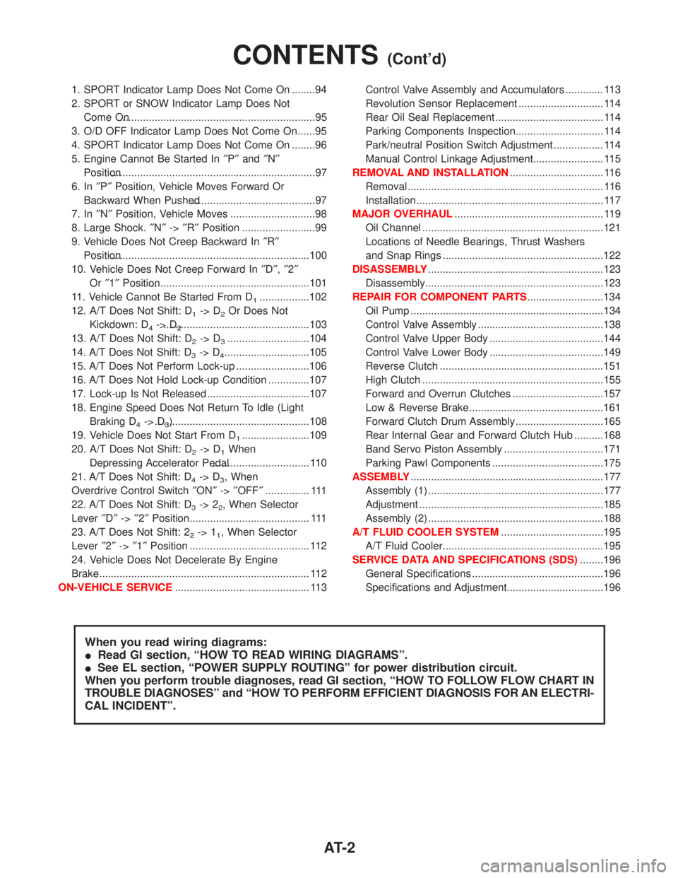
1. SPORT Indicator Lamp Does Not Come On ........94
2. SPORT or SNOW Indicator Lamp Does Not
Come On...................................................................95
3. O/D OFF Indicator Lamp Does Not Come On......95
4. SPORT Indicator Lamp Does Not Come On ........96
5. Engine Cannot Be Started In²P²and²N²
Position......................................................................97
6. In²P²Position, Vehicle Moves Forward Or
Backward When Pushed...........................................97
7. In²N²Position, Vehicle Moves .............................98
8. Large Shock.²N²->²R²Position .........................99
9. Vehicle Does Not Creep Backward In²R²
Position....................................................................100
10. Vehicle Does Not Creep Forward In²D²,²2²
Or²1²Position.........................................................101
11. Vehicle Cannot Be Started From D
1.................102
12. A/T Does Not Shift: D
1-> D2Or Does Not
Kickdown: D
4-> D2..................................................103
13. A/T Does Not Shift: D
2-> D3............................104
14. A/T Does Not Shift: D
3-> D4.............................105
15. A/T Does Not Perform Lock-up .........................106
16. A/T Does Not Hold Lock-up Condition ..............107
17. Lock-up Is Not Released ...................................107
18. Engine Speed Does Not Return To Idle (Light
Braking D
4-> D3) .....................................................108
19. Vehicle Does Not Start From D
1.......................109
20. A/T Does Not Shift: D
2-> D1When
Depressing Accelerator Pedal................................. 110
21. A/T Does Not Shift: D
4-> D3, When
Overdrive Control Switch²ON²->²OFF²............... 111
22. A/T Does Not Shift: D
3-> 22, When Selector
Lever²D²->²2²Position......................................... 111
23. A/T Does Not Shift: 2
2-> 11, When Selector
Lever²2²->²1²Position ......................................... 112
24. Vehicle Does Not Decelerate By Engine
Brake........................................................................ 112
ON-VEHICLE SERVICE.............................................. 113Control Valve Assembly and Accumulators ............. 113
Revolution Sensor Replacement ............................. 114
Rear Oil Seal Replacement ..................................... 114
Parking Components Inspection.............................. 114
Park/neutral Position Switch Adjustment ................. 114
Manual Control Linkage Adjustment........................ 115
REMOVAL AND INSTALLATION................................ 116
Removal ................................................................... 116
Installation ................................................................ 117
MAJOR OVERHAUL................................................... 119
Oil Channel ..............................................................121
Locations of Needle Bearings, Thrust Washers
and Snap Rings .......................................................122
DISASSEMBLY............................................................123
Disassembly.............................................................123
REPAIR FOR COMPONENT PARTS..........................134
Oil Pump ..................................................................134
Control Valve Assembly ...........................................138
Control Valve Upper Body .......................................144
Control Valve Lower Body .......................................149
Reverse Clutch ........................................................151
High Clutch ..............................................................155
Forward and Overrun Clutches ...............................157
Low & Reverse Brake..............................................161
Forward Clutch Drum Assembly ..............................165
Rear Internal Gear and Forward Clutch Hub ..........168
Band Servo Piston Assembly ..................................171
Parking Pawl Components ......................................175
ASSEMBLY..................................................................177
Assembly (1) ............................................................177
Adjustment ...............................................................185
Assembly (2) ............................................................188
A/T FLUID COOLER SYSTEM...................................195
A/T Fluid Cooler.......................................................195
SERVICE DATA AND SPECIFICATIONS (SDS)........196
General Specifications .............................................196
Specifications and Adjustment.................................196
When you read wiring diagrams:
IRead GI section, ªHOW TO READ WIRING DIAGRAMSº.
ISee EL section, ªPOWER SUPPLY ROUTINGº for power distribution circuit.
When you perform trouble diagnoses, read GI section, ªHOW TO FOLLOW FLOW CHART IN
TROUBLE DIAGNOSESº and ªHOW TO PERFORM EFFICIENT DIAGNOSIS FOR AN ELECTRI-
CAL INCIDENTº.
CONTENTS(Cont'd)
AT- 2
Page 7 of 1767
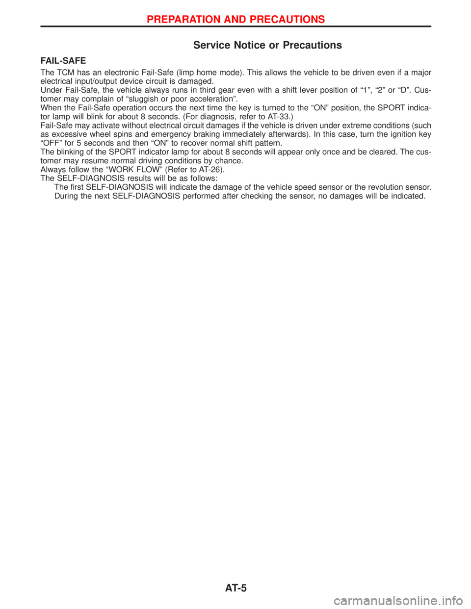
Service Notice or Precautions
FAIL-SAFE
The TCM has an electronic Fail-Safe (limp home mode). This allows the vehicle to be driven even if a major
electrical input/output device circuit is damaged.
Under Fail-Safe, the vehicle always runs in third gear even with a shift lever position of ª1º, ª2º or ªDº. Cus-
tomer may complain of ªsluggish or poor accelerationº.
When the Fail-Safe operation occurs the next time the key is turned to the ªONº position, the SPORT indica-
tor lamp will blink for about 8 seconds. (For diagnosis, refer to AT-33.)
Fail-Safe may activate without electrical circuit damages if the vehicle is driven under extreme conditions (such
as excessive wheel spins and emergency braking immediately afterwards). In this case, turn the ignition key
ªOFFº for 5 seconds and then ªONº to recover normal shift pattern.
The blinking of the SPORT indicator lamp for about 8 seconds will appear only once and be cleared. The cus-
tomer may resume normal driving conditions by chance.
Always follow the ªWORK FLOWº (Refer to AT-26).
The SELF-DIAGNOSIS results will be as follows:
The first SELF-DIAGNOSIS will indicate the damage of the vehicle speed sensor or the revolution sensor.
During the next SELF-DIAGNOSIS performed after checking the sensor, no damages will be indicated.
PREPARATION AND PRECAUTIONS
AT- 5
Page 13 of 1767
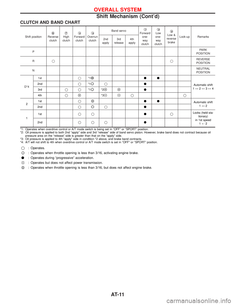
CLUTCH AND BAND CHART
Shift positionq6Reverse
clutchq7High
clutchq16Forward
clutchq18Overrun
clutchBand servoq
17Forward
one-
way
clutchq19Low
one-
way
clutchq20Low &
reverse
brakeLock-up Remarks
2nd
apply3rd
release4th
apply
PPARK
POSITION
RqqREVERSE
POSITION
NNEUTRAL
POSITION
D*41stq*1
vv
Automatic shift
1)2)3)4 2ndq*1
qv
3rdqq*1
*2v
4thq
*3qq
21stq
vv
Automatic shift
1)2
2ndq
qv
11stqqvqLocks (held sta-
tionary)
in 1st speed
1+2 2ndqqqv
*1: Operates when overdrive control or A/T mode switch is being set in ªOFFº or ªSPORTº position.
*2: Oil pressure is applied to both 2nd ªapplyº side and 3rd ªreleaseº side of band servo piston. However, brake band does not contract because oil
pressure area on the ªreleaseº side is greater than that on the ªapplyº side.
*3: Oil pressure is applied to 4th ªapplyº side in condition *2 above, and brake band contracts.
*4: A/T will not shift to 4th when overdrive control or A/T mode switch is set in ªOFFº or ªSPORTº position.
q: Operates.
: Operates when throttle opening is less than 3/16, activating engine brake.
v: Operates during ªprogressiveº acceleration.
: Operates but does not affect power transmission.
: Operates when throttle opening is less than 3/16, but does not affect engine brake.
OVERALL SYSTEM
Shift Mechanism (Cont'd)
AT-11
Page 14 of 1767
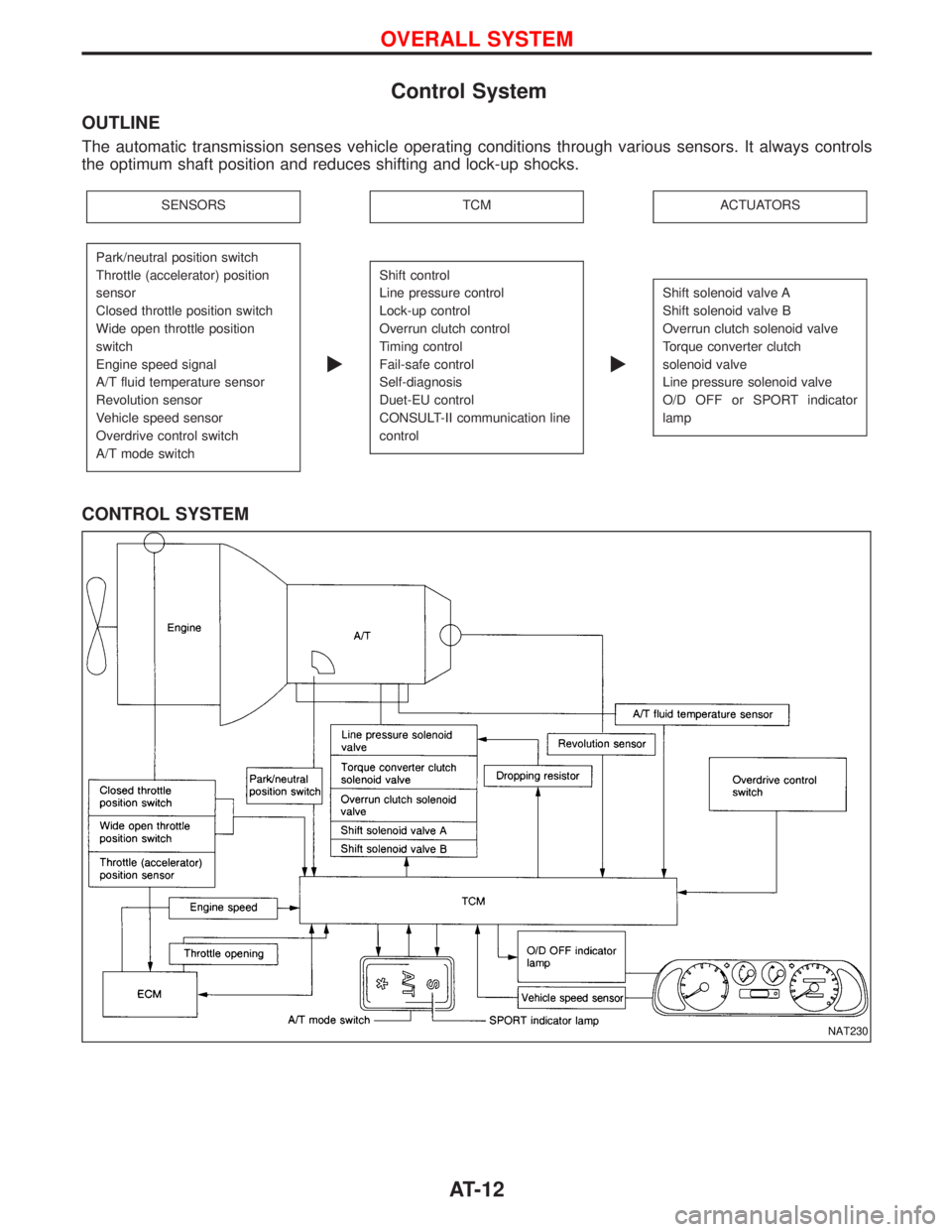
Control System
OUTLINE
The automatic transmission senses vehicle operating conditions through various sensors. It always controls
the optimum shaft position and reduces shifting and lock-up shocks.
SENSORSTCMACTUATORS
Park/neutral position switch
Throttle (accelerator) position
sensor
Closed throttle position switch
Wide open throttle position
switch
Engine speed signal
A/T fluid temperature sensor
Revolution sensor
Vehicle speed sensor
Overdrive control switch
A/T mode switch
E
Shift control
Line pressure control
Lock-up control
Overrun clutch control
Timing control
Fail-safe control
Self-diagnosis
Duet-EU control
CONSULT-II communication line
control
E
Shift solenoid valve A
Shift solenoid valve B
Overrun clutch solenoid valve
Torque converter clutch
solenoid valve
Line pressure solenoid valve
O/D OFF or SPORT indicator
lamp
CONTROL SYSTEM
NAT230
OVERALL SYSTEM
AT-12
Page 15 of 1767
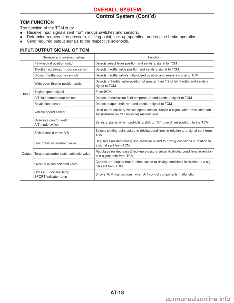
TCM FUNCTION
The function of the TCM is to:
IReceive input signals sent from various switches and sensors.
IDetermine required line pressure, shifting point, lock-up operation, and engine brake operation.
ISend required output signals to the respective solenoids.
INPUT/OUTPUT SIGNAL OF TCM
Sensors and solenoid valves Function
InputPark/neutral position switch Detects select lever position and sends a signal to TCM.
Throttle (accelerator) position sensor Detects throttle valve position and sends a signal to TCM.
Closed throttle position switch Detects throttle valve's fully-closed position and sends a signal to TCM.
Wide open throttle position switchDetects a throttle valve position of greater than 1/2 of full throttle and sends a
signal to TCM.
Engine speed signal From ECM.
A/T fluid temperature sensor Detects transmission fluid temperature and sends a signal to TCM.
Revolution sensor Detects output shaft rpm and sends a signal to TCM.
Vehicle speed sensorUsed as an auxiliary vehicle speed sensor. Sends a signal when revolution sen-
sor (installed on transmission) malfunctions.
Overdrive control switch
A/T mode switchSends a signal, which prohibits a shift to ªD
4º (overdrive) position, to the TCM.
OutputShift solenoid valve A/BSelects shifting point suited to driving conditions in relation to a signal sent from
TCM.
Line pressure solenoid valveRegulates (or decreases) line pressure suited to driving conditions in relation to
a signal sent from TCM.
Torque converter clutch solenoid valveRegulates (or decreases) lock-up pressure suited to driving conditions in relation
to a signal sent from TCM.
Overrun clutch solenoid valveControls an ªengine brakeº effect suited to driving conditions in relation to a sig-
nal sent from TCM.
O/D OFF indicator lamp
SPORT indicator lampShows TCM malfunctions, when A/T control components malfunction.
OVERALL SYSTEM
Control System (Cont'd)
AT-13
Page 24 of 1767
Introduction
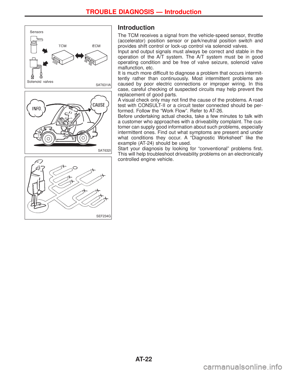
The TCM receives a signal from the vehicle-speed sensor, throttle
(accelerator) position sensor or park/neutral position switch and
provides shift control or lock-up control via solenoid valves.
Input and output signals must always be correct and stable in the
operation of the A/T system. The A/T system must be in good
operating condition and be free of valve seizure, solenoid valve
malfunction, etc.
It is much more difficult to diagnose a problem that occurs intermit-
tently rather than continuously. Most intermittent problems are
caused by poor electric connections or improper wiring. In this
case, careful checking of suspected circuits may help prevent the
replacement of good parts.
A visual check only may not find the cause of the problems. A road
test with CONSULT-II or a circuit tester connected should be per-
formed. Follow the ªWork Flowº. Refer to AT-26.
Before undertaking actual checks, take a few minutes to talk with
a customer who approaches with a driveability complaint. The cus-
tomer can supply good information about such problems, especially
intermittent ones. Find out what symptoms are present and under
what conditions they occur. A ªDiagnostic Worksheetº like the
example (AT-24) should be used.
Start your diagnosis by looking for ªconventionalº problems first.
This will help troubleshoot driveability problems on an electronically
controlled engine vehicle.
SAT631IA
SAT632I
SEF234G
TROUBLE DIAGNOSIS Ð Introduction
AT-22
Page 25 of 1767
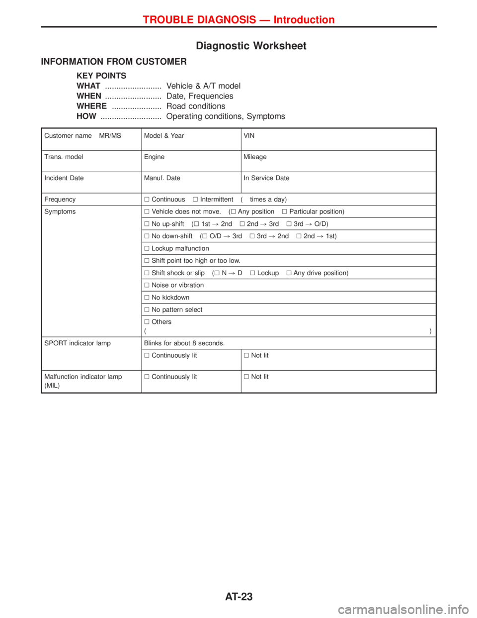
Diagnostic Worksheet
INFORMATION FROM CUSTOMER
KEY POINTS
WHAT......................... Vehicle & A/T model
WHEN......................... Date, Frequencies
WHERE...................... Road conditions
HOW........................... Operating conditions, Symptoms
Customer name MR/MS Model & Year VIN
Trans. model Engine Mileage
Incident Date Manuf. Date In Service Date
FrequencylContinuouslIntermittent ( times a day)
SymptomslVehicle does not move. (lAny positionlParticular position)
lNo up-shift (l1st,2ndl2nd,3rdl3rd,O/D)
lNo down-shift (lO/D,3rdl3rd,2ndl2nd,1st)
lLockup malfunction
lShift point too high or too low.
lShift shock or slip (lN,DlLockuplAny drive position)
lNoise or vibration
lNo kickdown
lNo pattern select
lOthers
()
SPORT indicator lamp Blinks for about 8 seconds.
lContinuously litlNot lit
Malfunction indicator lamp
(MIL)lContinuously litlNot lit
TROUBLE DIAGNOSIS Ð Introduction
AT-23