Page 1548 of 1767

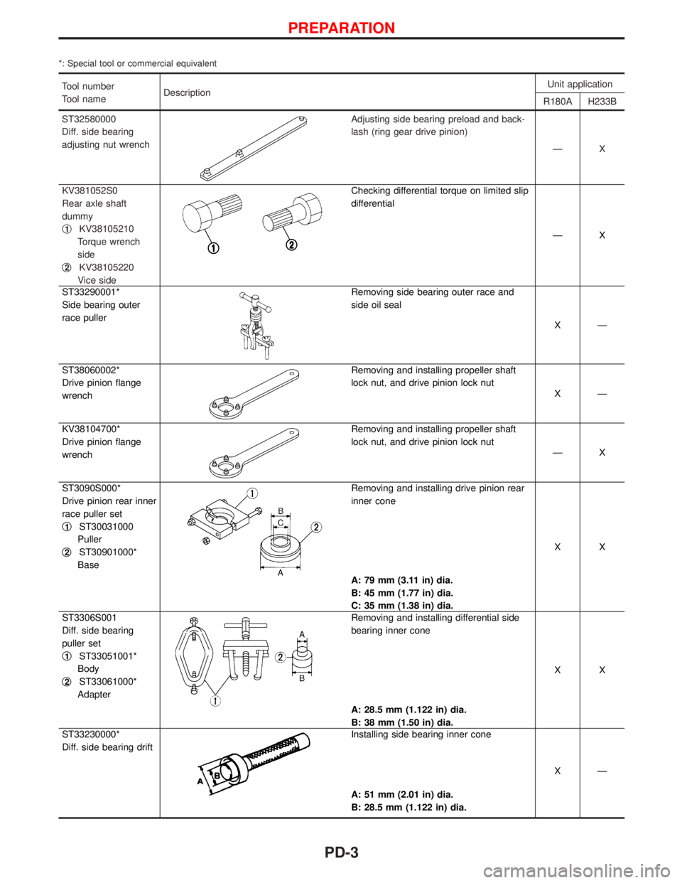
*: Special tool or commercial equivalent
Tool number
Tool nameDescriptionUnit application
R180A H233B
ST32580000
Diff. side bearing
adjusting nut wrench
Adjusting side bearing preload and back-
lash (ring gear drive pinion)
ÐX
KV381052S0
Rear axle shaft
dummy
q
1KV38105210
Torque wrench
side
q
2KV38105220
Vice side
Checking differential torque on limited slip
differential
ÐX
ST33290001*
Side bearing outer
race puller
Removing side bearing outer race and
side oil seal
XÐ
ST38060002*
Drive pinion flange
wrench
Removing and installing propeller shaft
lock nut, and drive pinion lock nut
XÐ
KV38104700*
Drive pinion flange
wrench
Removing and installing propeller shaft
lock nut, and drive pinion lock nut
ÐX
ST3090S000*
Drive pinion rear inner
race puller set
q
1ST30031000
Puller
q
2ST30901000*
Base
Removing and installing drive pinion rear
inner cone
A: 79 mm (3.11 in) dia.
B: 45 mm (1.77 in) dia.
C: 35 mm (1.38 in) dia.XX
ST3306S001
Diff. side bearing
puller set
q
1ST33051001*
Body
q
2ST33061000*
Adapter
Removing and installing differential side
bearing inner cone
A: 28.5 mm (1.122 in) dia.
B: 38 mm (1.50 in) dia.XX
ST33230000*
Diff. side bearing drift
Installing side bearing inner cone
A: 51 mm (2.01 in) dia.
B: 28.5 mm (1.122 in) dia.XÐ
PREPARATION
PD-3
Page 1557 of 1767

Removal
1. Remove front propeller shaft.
2. Remove drive shaft. Refer to FA section.
3. Remove engine mounting bolts and raise up engine.
4. Remove front final drive together with differential mounting
member.
Installation
1. Install front final drive assembly together with differential
mounting member.
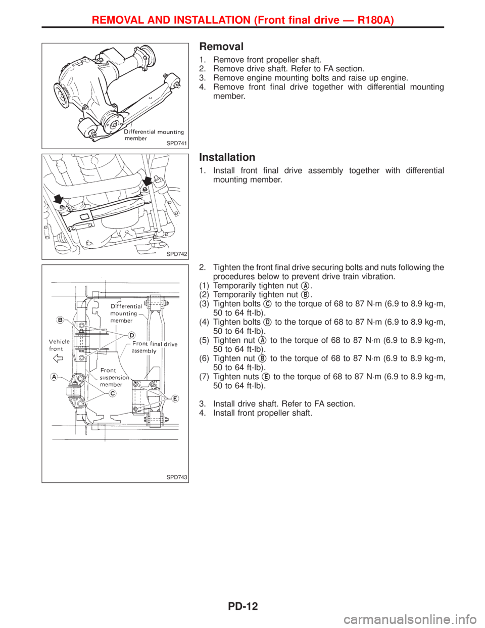
2. Tighten the front final drive securing bolts and nuts following the
procedures below to prevent drive train vibration.
(1) Temporarily tighten nutq
A.
(2) Temporarily tighten nutq
B.
(3) Tighten boltsq
Cto the torque of 68 to 87 N×m (6.9 to 8.9 kg-m,
50 to 64 ft-lb).
(4) Tighten boltsq
Dto the torque of 68 to 87 N×m (6.9 to 8.9 kg-m,
50 to 64 ft-lb).
(5) Tighten nutq
Ato the torque of 68 to 87 N×m (6.9 to 8.9 kg-m,
50 to 64 ft-lb).
(6) Tighten nutq
Bto the torque of 68 to 87 N×m (6.9 to 8.9 kg-m,
50 to 64 ft-lb).
(7) Tighten nutsq
Eto the torque of 68 to 87 N×m (6.9 to 8.9 kg-m,
50 to 64 ft-lb).
3. Install drive shaft. Refer to FA section.
4. Install front propeller shaft.
SPD741
SPD742
SPD743
REMOVAL AND INSTALLATION (Front final drive Ð R180A)
PD-12
Page 1561 of 1767
2. Remove extension tube and differential side shaft assembly.
3. Remove differential side flange.
4. Mark side retainers for identification. Remove side retainers.
Be careful not to confuse right and left side retainers and
shims.
5. Extract differential case from final drive housing.
6. Remove side outer races.
Tool number:
ST33290001
Be careful to keep the side bearing outer races together with
their respective inner cones Ð do not mix them up.
7. Remove side oil seal.
NPD005
SPD713
SPD639
SPD309
PD243
DISASSEMBLY (R180A)
Final Drive Housing (Cont'd)
PD-16
Page 1563 of 1767
Differential Case
1. Remove side bearing inner cones.
To prevent damage to bearing, engage puller jaws in grooves.
Assembly:
ST33065001
Tool number:
q
AST33051001
q
BST33061000
Be careful not to confuse the right and left hand parts.
2. Loosen ring gear bolts in a criss-cross fashion.
3. Tap ring gear off differential case with a soft hammer.
Tap evenly all around to keep ring gear from binding.
4. Separate L.H. and R.H. differential cases.
Put match marks on both L.H. and R.H. differential cases.
SPD642
SPD022
SPD024
SPD643
DISASSEMBLY (R180A)
PD-18
Page 1564 of 1767
Extension Tube and Differential Side Shaft
1. Remove differential side shaft assembly from extension tube.
2. Cut rear axle bearing collar with cold chisel. Be careful not to
damage differential side shaft.
3. Install differential side shaft into extension tube and secure with
bolts. Remove extension tube retainer from differential side
shaft.
4. Remove grease seal.
SPD644
SPD645
SPD646
SPD647
DISASSEMBLY (R180A)
PD-19
Page 1565 of 1767
Ring Gear and Drive Pinion
Check gear teeth for scoring, cracking or chipping.
If any damaged part is evident, replace ring gear and drive pinion
as a set (hypoid gear set).
Differential Case Assembly
Check mating surfaces of differential case, side gears, pinion mate
gears, pinion mate shaft and thrust washers.
Bearing
1. Thoroughly clean bearing.
2. Check bearings for wear, scratches, pitting or flaking.
Check tapered roller bearing for smooth rotation. If damaged,
replace outer race and inner cone as a set.
SPD648
SPD715
INSPECTION (R180A)
PD-20
Page 1569 of 1767
Side Bearing Preload
1. To simplify the job, make a chart like the one below to organize
your calculations.
LETTERSHUNDREDTHS OF
A MILLIMETER
A þ Left housing
B þ Right housing
C þ Differential case
D þ Differential case
E þ Left side bearing
F þ Right side bearing
G
1þ Left side retainer
G
2þ Right side retainer
2. Write the following numbers down in the chart.
A & B: Figures marked on final drive housing.
C & D: Figures marked on differential case.
G
1&G2: Figures marked on side retainer.
SPD650
SPD651
SPD652
ADJUSTMENT (R180A)
PD-24
Page 1573 of 1767
Extension Tube and Differential Side Shaft
1. Measure rear axle bearing end play.
Rear axle bearing end play (A þ B):
0.1 mm (0.0039 in) or less
The end play can be adjusted with bearing adjusting shim.
(Refer to PD-57.)
2. Install oil seal.
3. Install the spacer, grease seal, extension tube retainer, adjust-
ing shim, shim and shim collar onto the differential side shaft.
4. Install differential side shaft assembly into extension tube.
SPD699
SPD654
SPD655
ASSEMBLY (R180A)
PD-28