Page 701 of 1767
qA
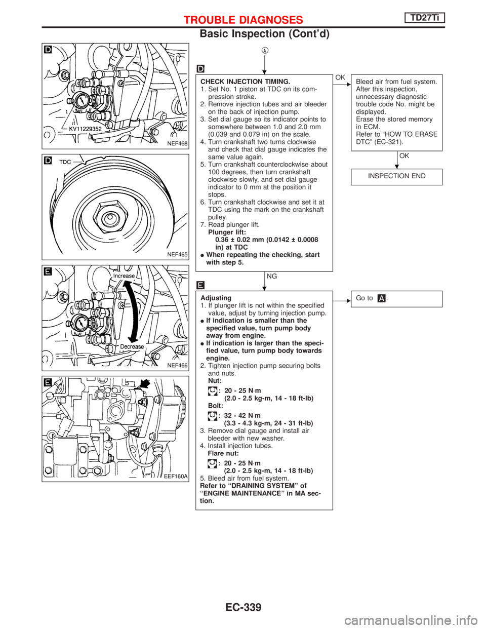
CHECK INJECTION TIMING.
1. Set No. 1 piston at TDC on its com-
pression stroke.
2. Remove injection tubes and air bleeder
on the back of injection pump.
3. Set dial gauge so its indicator points to
somewhere between 1.0 and 2.0 mm
(0.039 and 0.079 in) on the scale.
4. Turn crankshaft two turns clockwise
and check that dial gauge indicates the
same value again.
5. Turn crankshaft counterclockwise about
100 degrees, then turn crankshaft
clockwise slowly, and set dial gauge
indicator to 0 mm at the position it
stops.
6. Turn crankshaft clockwise and set it at
TDC using the mark on the crankshaft
pulley.
7. Read plunger lift.
Plunger lift:
0.36 0.02 mm (0.0142 0.0008
in) at TDC
IWhen repeating the checking, start
with step 5.
NG
EOK
Bleed air from fuel system.
After this inspection,
unnecessary diagnostic
trouble code No. might be
displayed.
Erase the stored memory
in ECM.
Refer to ªHOW TO ERASE
DTCº (EC-321).
OK
INSPECTION END
Adjusting
1. If plunger lift is not within the specified
value, adjust by turning injection pump.
IIf indication is smaller than the
specified value, turn pump body
away from engine.
IIf indication is larger than the speci-
fied value, turn pump body towards
engine.
2. Tighten injection pump securing bolts
and nuts.
Nut:
: 20-25N×m
(2.0 - 2.5 kg-m, 14 - 18 ft-lb)
Bolt:
: 32-42N×m
(3.3 - 4.3 kg-m, 24 - 31 ft-lb)
3. Remove dial gauge and install air
bleeder with new washer.
4. Install injection tubes.
Flare nut:
: 20-25N×m
(2.0 - 2.5 kg-m, 14 - 18 ft-lb)
5. Bleed air from fuel system.
Refer to ªDRAINING SYSTEMº of
ªENGINE MAINTENANCEº in MA sec-
tion.
EGo to.
NEF468
NEF465
NEF466
EEF160A
H
H
H
TROUBLE DIAGNOSESTD27Ti
Basic Inspection (Cont'd)
EC-339
Page 1158 of 1767
VALVE OIL SEAL
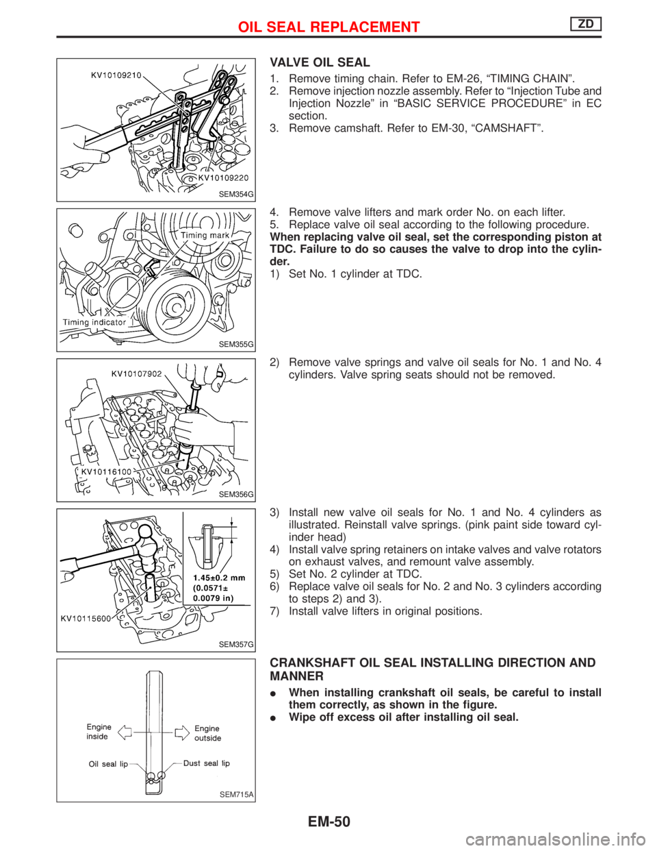
1. Remove timing chain. Refer to EM-26, ªTIMING CHAINº.
2. Remove injection nozzle assembly. Refer to ªInjection Tube and
Injection Nozzleº in ªBASIC SERVICE PROCEDUREº in EC
section.
3. Remove camshaft. Refer to EM-30, ªCAMSHAFTº.
4. Remove valve lifters and mark order No. on each lifter.
5. Replace valve oil seal according to the following procedure.
When replacing valve oil seal, set the corresponding piston at
TDC. Failure to do so causes the valve to drop into the cylin-
der.
1) Set No. 1 cylinder at TDC.
2) Remove valve springs and valve oil seals for No. 1 and No. 4
cylinders. Valve spring seats should not be removed.
3) Install new valve oil seals for No. 1 and No. 4 cylinders as
illustrated. Reinstall valve springs. (pink paint side toward cyl-
inder head)
4) Install valve spring retainers on intake valves and valve rotators
on exhaust valves, and remount valve assembly.
5) Set No. 2 cylinder at TDC.
6) Replace valve oil seals for No. 2 and No. 3 cylinders according
to steps 2) and 3).
7) Install valve lifters in original positions.
CRANKSHAFT OIL SEAL INSTALLING DIRECTION AND
MANNER
IWhen installing crankshaft oil seals, be careful to install
them correctly, as shown in the figure.
IWipe off excess oil after installing oil seal.
SEM354G
SEM355G
SEM356G
SEM357G
SEM715A
OIL SEAL REPLACEMENTZD
EM-50
Page 1162 of 1767
IDLER GEAR OIL CLEARANCE
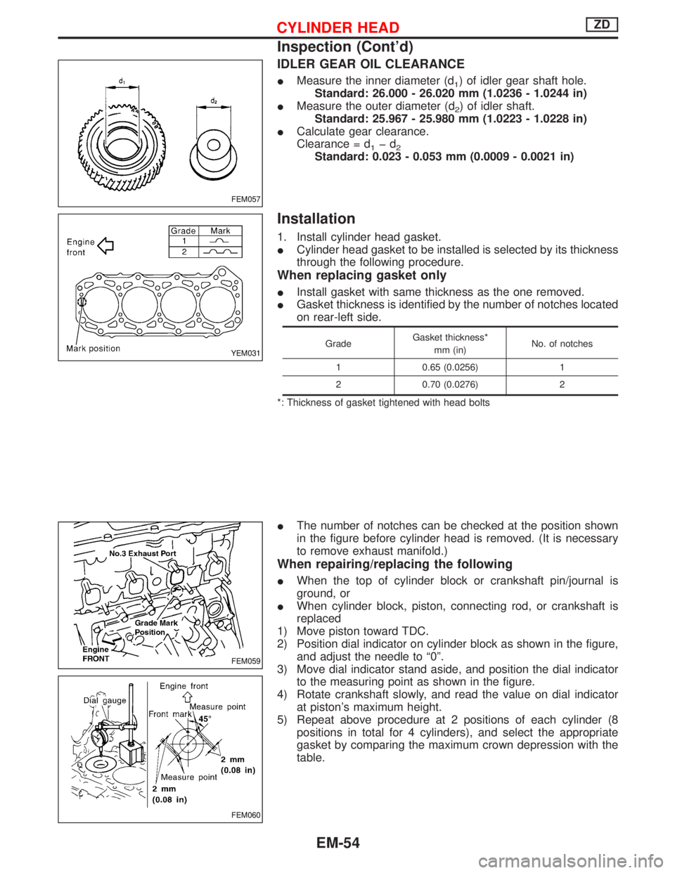
IMeasure the inner diameter (d1) of idler gear shaft hole.
Standard: 26.000 - 26.020 mm (1.0236 - 1.0244 in)
IMeasure the outer diameter (d
2) of idler shaft.
Standard: 25.967 - 25.980 mm (1.0223 - 1.0228 in)
ICalculate gear clearance.
Clearance = d
1þd2Standard: 0.023 - 0.053 mm (0.0009 - 0.0021 in)
Installation
1. Install cylinder head gasket.
ICylinder head gasket to be installed is selected by its thickness
through the following procedure.
When replacing gasket only
IInstall gasket with same thickness as the one removed.
IGasket thickness is identified by the number of notches located
on rear-left side.
GradeGasket thickness*
mm (in)No. of notches
1 0.65 (0.0256) 1
2 0.70 (0.0276) 2
*: Thickness of gasket tightened with head bolts
IThe number of notches can be checked at the position shown
in the figure before cylinder head is removed. (It is necessary
to remove exhaust manifold.)
When repairing/replacing the following
IWhen the top of cylinder block or crankshaft pin/journal is
ground, or
IWhen cylinder block, piston, connecting rod, or crankshaft is
replaced
1) Move piston toward TDC.
2) Position dial indicator on cylinder block as shown in the figure,
and adjust the needle to ª0º.
3) Move dial indicator stand aside, and position the dial indicator
to the measuring point as shown in the figure.
4) Rotate crankshaft slowly, and read the value on dial indicator
at piston's maximum height.
5) Repeat above procedure at 2 positions of each cylinder (8
positions in total for 4 cylinders), and select the appropriate
gasket by comparing the maximum crown depression with the
table.
FEM057
YEM031
FEM059
FEM060
CYLINDER HEADZD
Inspection (Cont'd)
EM-54
Page 1165 of 1767
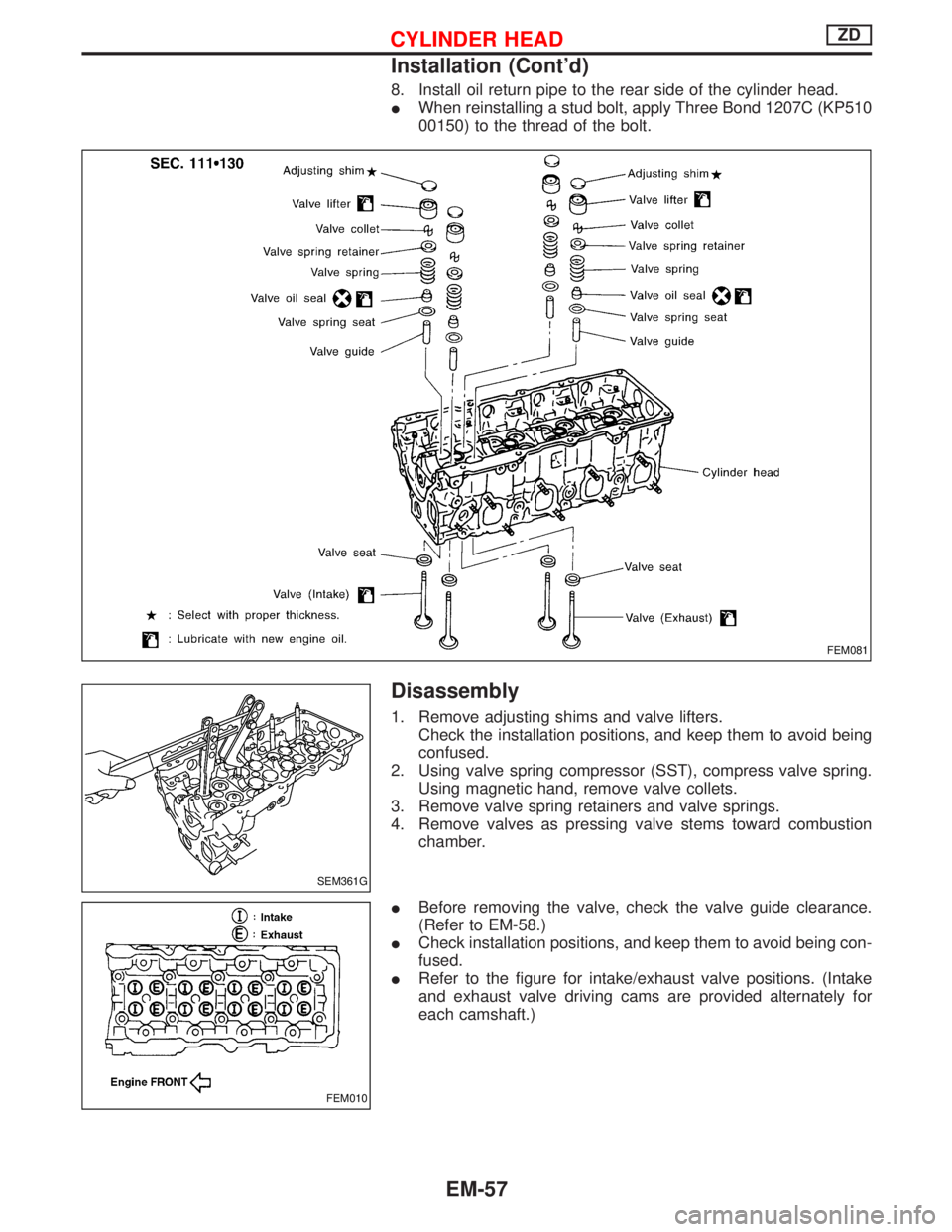
8. Install oil return pipe to the rear side of the cylinder head.
IWhen reinstalling a stud bolt, apply Three Bond 1207C (KP510
00150) to the thread of the bolt.
Disassembly
1. Remove adjusting shims and valve lifters.
Check the installation positions, and keep them to avoid being
confused.
2. Using valve spring compressor (SST), compress valve spring.
Using magnetic hand, remove valve collets.
3. Remove valve spring retainers and valve springs.
4. Remove valves as pressing valve stems toward combustion
chamber.
IBefore removing the valve, check the valve guide clearance.
(Refer to EM-58.)
ICheck installation positions, and keep them to avoid being con-
fused.
IRefer to the figure for intake/exhaust valve positions. (Intake
and exhaust valve driving cams are provided alternately for
each camshaft.)
FEM081
SEM361G
FEM010
CYLINDER HEADZD
Installation (Cont'd)
EM-57
Page 1166 of 1767
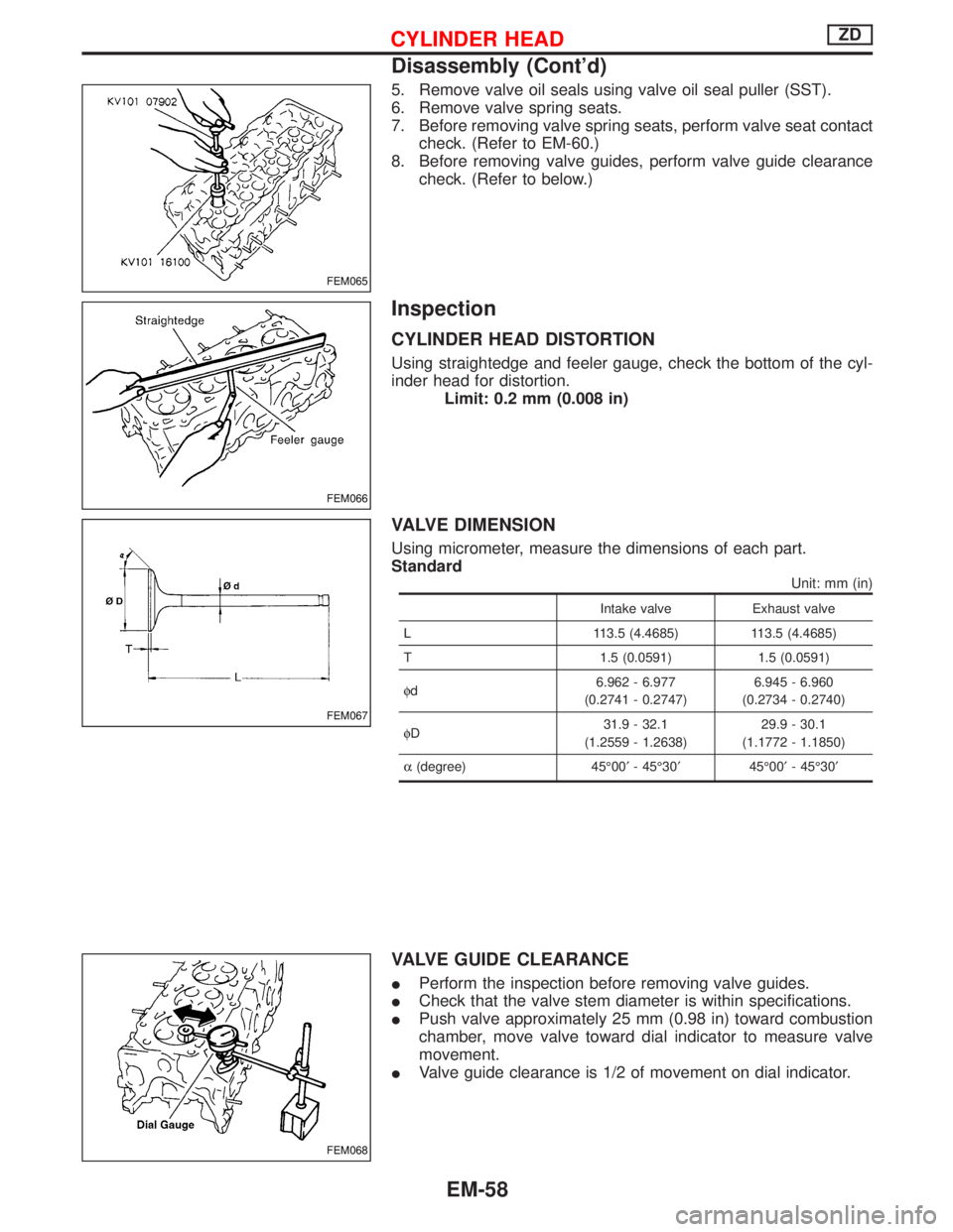
5. Remove valve oil seals using valve oil seal puller (SST).
6. Remove valve spring seats.
7. Before removing valve spring seats, perform valve seat contact
check. (Refer to EM-60.)
8. Before removing valve guides, perform valve guide clearance
check. (Refer to below.)
Inspection
CYLINDER HEAD DISTORTION
Using straightedge and feeler gauge, check the bottom of the cyl-
inder head for distortion.
Limit: 0.2 mm (0.008 in)
VALVE DIMENSION
Using micrometer, measure the dimensions of each part.
Standard
Unit: mm (in)
Intake valve Exhaust valve
L 113.5 (4.4685) 113.5 (4.4685)
T 1.5 (0.0591) 1.5 (0.0591)
fd6.962 - 6.977
(0.2741 - 0.2747)6.945 - 6.960
(0.2734 - 0.2740)
fD31.9 - 32.1
(1.2559 - 1.2638)29.9 - 30.1
(1.1772 - 1.1850)
a(degree) 45É00¢- 45É30¢45É00¢- 45É30¢
VALVE GUIDE CLEARANCE
IPerform the inspection before removing valve guides.
ICheck that the valve stem diameter is within specifications.
IPush valve approximately 25 mm (0.98 in) toward combustion
chamber, move valve toward dial indicator to measure valve
movement.
IValve guide clearance is 1/2 of movement on dial indicator.
FEM065
FEM066
FEM067
FEM068
CYLINDER HEADZD
Disassembly (Cont'd)
EM-58
Page 1189 of 1767
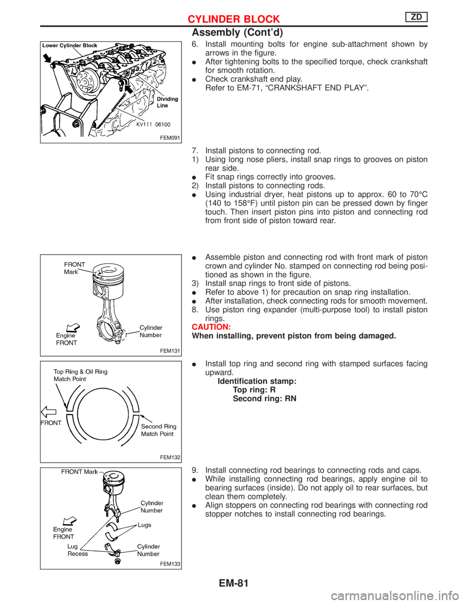
6. Install mounting bolts for engine sub-attachment shown by
arrows in the figure.
IAfter tightening bolts to the specified torque, check crankshaft
for smooth rotation.
ICheck crankshaft end play.
Refer to EM-71, ªCRANKSHAFT END PLAYº.
7. Install pistons to connecting rod.
1) Using long nose pliers, install snap rings to grooves on piston
rear side.
IFit snap rings correctly into grooves.
2) Install pistons to connecting rods.
IUsing industrial dryer, heat pistons up to approx. 60 to 70ÉC
(140 to 158ÉF) until piston pin can be pressed down by finger
touch. Then insert piston pins into piston and connecting rod
from front side of piston toward rear.
IAssemble piston and connecting rod with front mark of piston
crown and cylinder No. stamped on connecting rod being posi-
tioned as shown in the figure.
3) Install snap rings to front side of pistons.
IRefer to above 1) for precaution on snap ring installation.
IAfter installation, check connecting rods for smooth movement.
8. Use piston ring expander (multi-purpose tool) to install piston
rings.
CAUTION:
When installing, prevent piston from being damaged.
IInstall top ring and second ring with stamped surfaces facing
upward.
Identification stamp:
Top ring: R
Second ring: RN
9. Install connecting rod bearings to connecting rods and caps.
IWhile installing connecting rod bearings, apply engine oil to
bearing surfaces (inside). Do not apply oil to rear surfaces, but
clean them completely.
IAlign stoppers on connecting rod bearings with connecting rod
stopper notches to install connecting rod bearings.
FEM091
FEM131
FEM132
FEM133
CYLINDER BLOCKZD
Assembly (Cont'd)
EM-81
Page 1190 of 1767
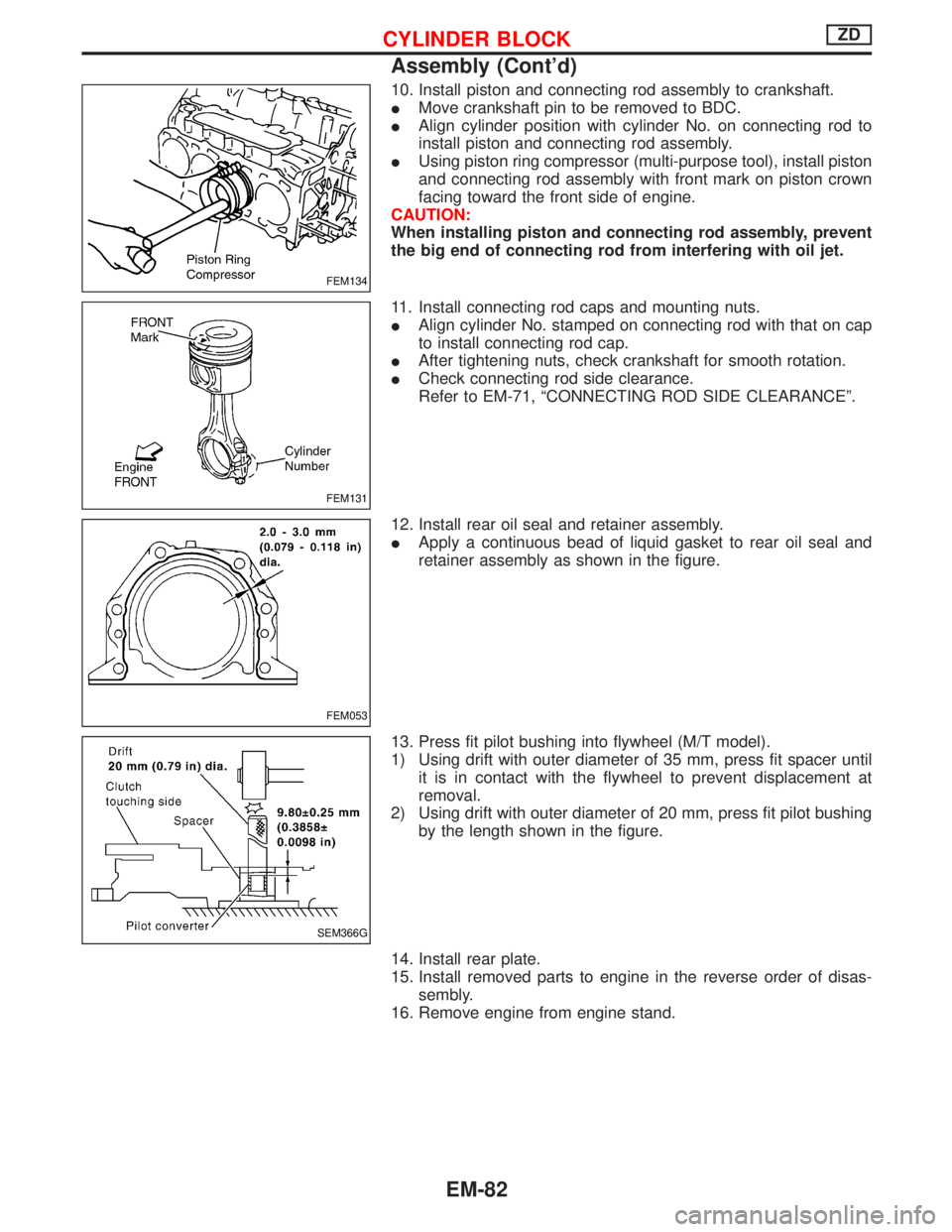
10. Install piston and connecting rod assembly to crankshaft.
IMove crankshaft pin to be removed to BDC.
IAlign cylinder position with cylinder No. on connecting rod to
install piston and connecting rod assembly.
IUsing piston ring compressor (multi-purpose tool), install piston
and connecting rod assembly with front mark on piston crown
facing toward the front side of engine.
CAUTION:
When installing piston and connecting rod assembly, prevent
the big end of connecting rod from interfering with oil jet.
11. Install connecting rod caps and mounting nuts.
IAlign cylinder No. stamped on connecting rod with that on cap
to install connecting rod cap.
IAfter tightening nuts, check crankshaft for smooth rotation.
ICheck connecting rod side clearance.
Refer to EM-71, ªCONNECTING ROD SIDE CLEARANCEº.
12. Install rear oil seal and retainer assembly.
IApply a continuous bead of liquid gasket to rear oil seal and
retainer assembly as shown in the figure.
13. Press fit pilot bushing into flywheel (M/T model).
1) Using drift with outer diameter of 35 mm, press fit spacer until
it is in contact with the flywheel to prevent displacement at
removal.
2) Using drift with outer diameter of 20 mm, press fit pilot bushing
by the length shown in the figure.
14. Install rear plate.
15. Install removed parts to engine in the reverse order of disas-
sembly.
16. Remove engine from engine stand.
FEM134
FEM131
FEM053
SEM366G
CYLINDER BLOCKZD
Assembly (Cont'd)
EM-82
Page 1241 of 1767
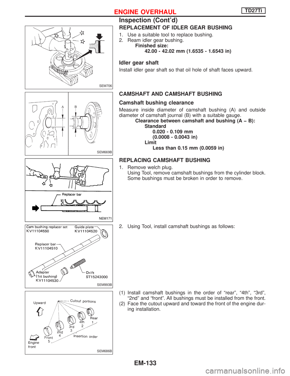
REPLACEMENT OF IDLER GEAR BUSHING
1. Use a suitable tool to replace bushing.
2. Ream idler gear bushing.
Finished size:
42.00 - 42.02 mm (1.6535 - 1.6543 in)
Idler gear shaft
Install idler gear shaft so that oil hole of shaft faces upward.
CAMSHAFT AND CAMSHAFT BUSHING
Camshaft bushing clearance
Measure inside diameter of camshaft bushing (A) and outside
diameter of camshaft journal (B) with a suitable gauge.
Clearance between camshaft and bushing (A þ B):
Standard
0.020 - 0.109 mm
(0.0008 - 0.0043 in)
Limit
Less than 0.15 mm (0.0059 in)
REPLACING CAMSHAFT BUSHING
1. Remove welch plug.
Using Tool, remove camshaft bushings from the cylinder block.
Some bushings must be broken in order to remove.
2. Using Tool, install camshaft bushings as follows:
(1) Install camshaft bushings in the order of ªrearº, ª4thº, ª3rdº,
ª2ndº and ªfrontº. All bushings must be installed from the front.
(2) Face the cutout upward and toward the front of the engine dur-
ing installation.
SEM706
SEM669B
NEM171
SEM993B
SEM686B
ENGINE OVERHAULTD27Ti
Inspection (Cont'd)
EM-133