Page 745 of 1767

Diagnostic Procedure
INSPECTION START
CHECK FOR AIR IN FUEL FILTER.
1. Move priming pump up and down to
purge air from fuel filter.
2. Perform ªDIAGNOSTIC TROUBLE
CODE CONFIRMATION PROCE-
DUREº.
CHECK POWER SUPPLY.
1. Turn ignition switch to ªLOCKº position.
2. Disconnect TVC and shut-off (injection
timing control valve) harness connec-
tor.
3. Turn ignition switch to ªONº position.
4. Check voltage between TVC and shut-
off (injection timing control valve) con-
nector terminalq
9and engine ground
with CONSULT-II or tester.
Voltage: Battery voltage
OK
ENG
Check the following:
IHarness connector
M787,F66
I20A fuse
IECM relay
IHarness for open or
short-circuit between
TVC and shut-off (injec-
tion timing control valve)
harness connector and
fuse box.
If NG, replace 20A fuse or
ECM relay, harness or con-
nectors.
CHECK OUTPUT SIGNAL CIRCUIT.
1. Turn ignition switch to ªLOCKº position.
2. Disconnect ECM harness connector.
3. Check harness continuity between TVC
and shut-off (injection timing control
valve) connector terminalq
8and ECM
terminals
202. Refer to wiring dia-
gram.
Continuity should exist.
If OK, check harness for short-circuit.
OK
ENG
Check the following:
IHarness for open or
short-circuit between
TVC and shut-off (injec-
tion timing control valve)
and ECM
If NG, repair harness or
connectors.
CHECK GROUND CIRCUIT.
1. Disconnect ECM harness connector.
2. Check harness continuity between
ECM connector terminal
349and TVC
and shut-off (injection timing control
valve) connector terminalq
10. Refer to
wiring diagram.
Continuity should exist.
If OK, check harness of short-circuit.
OK
ENG
Repair harness or connec-
tors
qA
YEC256A
NEF463
MEC947D
H
H
H
H
H
DTC P0216 INJ TIMING CONT/V, DTC P1246 F/INJ TIMG F/BTD27Ti
EC-383
Page 748 of 1767
Wiring Diagram
YEC146A
DTC P0335 CRANK POS SEN (TDC)TD27Ti
EC-386
Page 749 of 1767

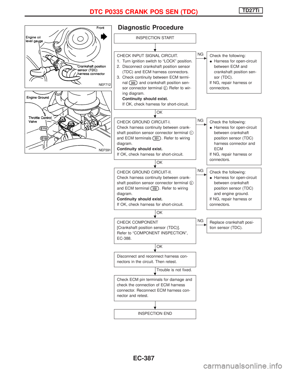
Diagnostic Procedure
INSPECTION START
CHECK INPUT SIGNAL CIRCUIT.
1. Turn ignition switch to ªLOCKº position.
2. Disconnect crankshaft position sensor
(TDC) and ECM harness connectors.
3. Check continuity between ECM termi-
nal
344and crankshaft position sen-
sor connector terminalq
2. Refer to wir-
ing diagram.
Continuity should exist.
If OK, check harness for short-circuit.
OK
ENG
Check the following:
IHarness for open-circuit
between ECM and
crankshaft position sen-
sor (TDC).
If NG, repair harness or
connectors.
CHECK GROUND CIRCUIT-I.
Check harness continuity between crank-
shaft position sensor connector terminalq
1
and ECM terminals331. Refer to wiring
diagram.
Continuity should exist.
If OK, check harness for short-circuit.
OK
ENG
Check the following:
IHarness for open-circuit
between crankshaft
position sensor (TDC)
harness connector and
ECM
If NG, repair harness or
connectors.
CHECK GROUND CIRCUIT-II.
Check harness continuity between crank-
shaft position sensor connector terminalq
3
and ECM terminal332. Refer to wiring
diagram.
Continuity should exist.
If OK, check harness for short-circuit.
OK
ENG
Check the following:
IHarness for open-circuit
between crankshaft
position sensor (TDC)
and engine ground.
If NG, repair harness or
connectors.
CHECK COMPONENT
[Crankshaft position sensor (TDC)].
Refer to ªCOMPONENT INSPECTIONº,
EC-388.
OK
ENG
Replace crankshaft posi-
tion sensor (TDC).
Disconnect and reconnect harness con-
nectors in the circuit. Then retest.
Trouble is not fixed.
Check ECM pin terminals for damage and
check the connection of ECM harness
connector. Reconnect ECM harness con-
nector and retest.
INSPECTION END
NEF712
NEF591
H
H
H
H
H
H
H
DTC P0335 CRANK POS SEN (TDC)TD27Ti
EC-387
Page 753 of 1767
Wiring Diagram
LHD MODELS
YEC151A
DTC P0380 GLOW RELAY, DTC P0381 GLOW LAMPTD27Ti
EC-391
Page 754 of 1767
RHD MODELS
YEC152A
DTC P0380 GLOW RELAY, DTC P0381 GLOW LAMPTD27Ti
Wiring Diagram (Cont'd)
EC-392
Page 755 of 1767

Diagnostic Procedure
INSPECTION START
Check fuel level, fuel supply system,
starter motor, etc.
OK
ENG
Correct.
Check that all glow plug connecting plate
nuts are installed correctly.
OK
ENG
Install correctly.
CHECK OVERALL FUNCTION.
Check entire glow control system.
NG
EOK
CHECK COMPONENT
(Glow plug).
Refer to EC-396.
CHECK VOLTAGE BETWEEN GLOW
RELAY AND GROUND.
1. Disconnect glow relay.
2. Check voltage between glow relay con-
nector terminalq
5and engine ground
with tester.
Voltage: Battery voltage
OK
ENG
Check the following:
I80A fusible link in fusible
link box
IHarness continuity
between glow relay and
battery positive terminal.
If NG, replace fuse or fus-
ible link or repair harness
or connectors.
CHECK VOLTAGE BETWEEN GLOW
RELAY AND GROUND.
1. Turn ignition switch to ªONº position.
2. Check voltage between glow relay con-
nector terminalsq
2and engine ground
with tester.
Voltage: Battery voltage
OK
ENG
Check the following:
I20A fusible link in fusible
link box
IECM relay
IHarness continuity
between glow relay and
battery positive terminal.
If NG, replace fuse or fus-
ible link or repair harness
or connectors.
CHECK OUTPUT SIGNAL CIRCUIT.
1. Turn ignition switch to ªLOCKº position.
2. Disconnect ECM harness connector.
3. Check harness continuity between
ECM connector terminal
214and
glow relay connector terminalq
1. Refer
to wiring diagram.
Continuity should exist.
If OK, check harness for short-circuit.
OK
ENG
Check the following.
IHarness connectors
M787,F66(LHD mod-
els)
IHarness continuity
between glow relay and
ECM
If NG, repair harness or
connectors.
CHECK HARNESS CONTINUITY
BETWEEN GLOW RELAY AND GLOW
PLUG.
1. Disconnect glow plug connector.
2. Check harness continuity between glow
relay connector terminalq
3and glow
plug connector terminalq
1. Refer to
wiring diagram.
Continuity should exist.
If OK, check harness for short-circuit.
OK
ENG
Check the following.
IHarness connectors
M740,E142
IHarness continuity
between glow relay and
glow plug
If NG, repair harness or
connectors.
qA
NEF504
MEC950D
MEC951D
H
H
H
H
H
H
H
H
DTC P0380 GLOW RELAY, DTC P0381 GLOW LAMPTD27Ti
EC-393
Page 760 of 1767
Wiring Diagram
YEC147A
DTC P0500 VEHICLE SPEED SENTD27Ti
EC-398
Page 761 of 1767

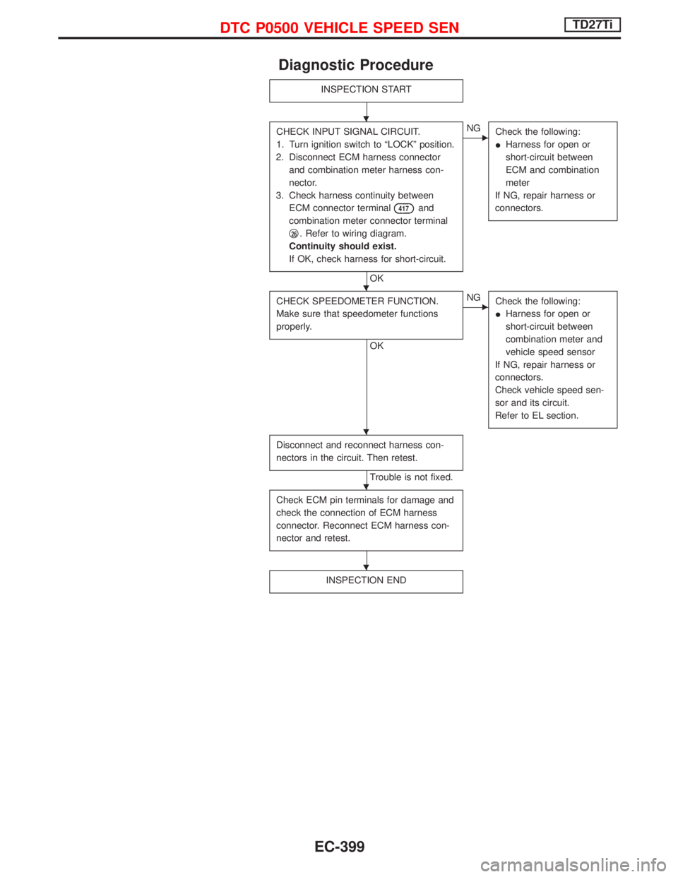
Diagnostic Procedure
INSPECTION START
CHECK INPUT SIGNAL CIRCUIT.
1. Turn ignition switch to ªLOCKº position.
2. Disconnect ECM harness connector
and combination meter harness con-
nector.
3. Check harness continuity between
ECM connector terminal
417and
combination meter connector terminal
q
26. Refer to wiring diagram.
Continuity should exist.
If OK, check harness for short-circuit.
OK
ENG
Check the following:
IHarness for open or
short-circuit between
ECM and combination
meter
If NG, repair harness or
connectors.
CHECK SPEEDOMETER FUNCTION.
Make sure that speedometer functions
properly.
OK
ENG
Check the following:
IHarness for open or
short-circuit between
combination meter and
vehicle speed sensor
If NG, repair harness or
connectors.
Check vehicle speed sen-
sor and its circuit.
Refer to EL section.
Disconnect and reconnect harness con-
nectors in the circuit. Then retest.
Trouble is not fixed.
Check ECM pin terminals for damage and
check the connection of ECM harness
connector. Reconnect ECM harness con-
nector and retest.
INSPECTION END
H
H
H
H
H
DTC P0500 VEHICLE SPEED SENTD27Ti
EC-399