Page 782 of 1767
Wiring Diagram
LHD MODELS
YEC163A
DTC P1217 OVER HEATTD27Ti
EC-420
Page 783 of 1767

Diagnostic Procedure
INSPECTION START
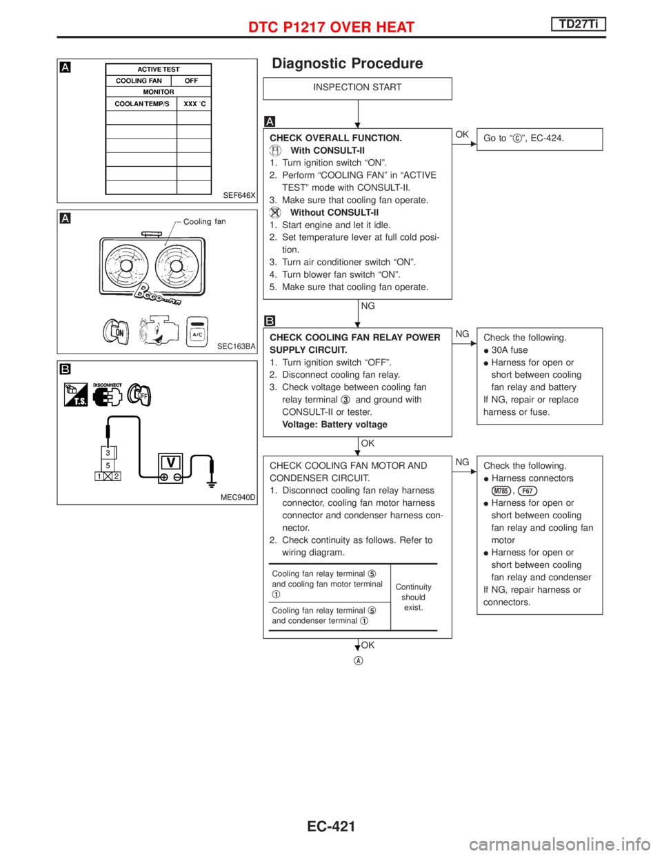
CHECK OVERALL FUNCTION.
With CONSULT-II
1. Turn ignition switch ªONº.
2. Perform ªCOOLING FANº in ªACTIVE
TESTº mode with CONSULT-II.
3. Make sure that cooling fan operate.
Without CONSULT-II
1. Start engine and let it idle.
2. Set temperature lever at full cold posi-
tion.
3. Turn air conditioner switch ªONº.
4. Turn blower fan switch ªONº.
5. Make sure that cooling fan operate.
NG
EOK
Go to ªqCº, EC-424.
CHECK COOLING FAN RELAY POWER
SUPPLY CIRCUIT.
1. Turn ignition switch ªOFFº.
2. Disconnect cooling fan relay.
3. Check voltage between cooling fan
relay terminalq
3and ground with
CONSULT-II or tester.
Voltage: Battery voltage
OK
ENG
Check the following.
I30A fuse
IHarness for open or
short between cooling
fan relay and battery
If NG, repair or replace
harness or fuse.
CHECK COOLING FAN MOTOR AND
CONDENSER CIRCUIT.
1. Disconnect cooling fan relay harness
connector, cooling fan motor harness
connector and condenser harness con-
nector.
2. Check continuity as follows. Refer to
wiring diagram.
OK
ENG
Check the following.
IHarness connectors
M785,F67
IHarness for open or
short between cooling
fan relay and cooling fan
motor
IHarness for open or
short between cooling
fan relay and condenser
If NG, repair harness or
connectors.
qA
Cooling fan relay terminalq5and cooling fan motor terminal
q1Continuity
should
exist.
Cooling fan relay terminalq
5and condenser terminalq1
SEF646X
SEC163BA
MEC940D
H
H
H
H
DTC P1217 OVER HEATTD27Ti
EC-421
Page 784 of 1767

qA
CHECK COOLING FAN MOTOR AND
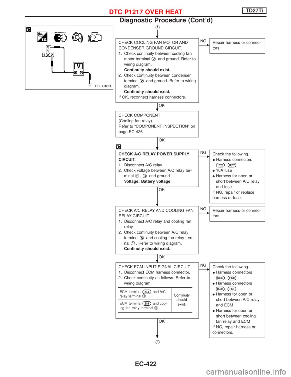
CONDENSER GROUND CIRCUIT.
1. Check continuity between cooling fan
motor terminalq
2and ground. Refer to
wiring diagram.
Continuity should exist.
2. Check continuity between condenser
terminalq
2and ground. Refer to wiring
diagram.
Continuity should exist.
If OK, reconnect harness connectors.
OK
ENG
Repair harness or connec-
tors.
CHECK COMPONENT
(Cooling fan relay).
Refer to ªCOMPONENT INSPECTIONº on
page EC-426.
OK
CHECK A/C RELAY POWER SUPPLY
CIRCUIT.
1. Disconnect A/C relay.
2. Check voltage between A/C relay ter-
minalq
2,q3and ground.
Voltage: Battery voltage
OK
ENG
Check the following.
IHarness connectors
F120,M812
I10A fuse
IHarness for open or
short between A/C relay
and fuse
If NG, repair or replace
harness or fuse.
CHECK A/C RELAY AND COOLING FAN
RELAY CIRCUIT.
1. Disconnect A/C relay and cooling fan
relay.
2. Check continuity between A/C relay
terminalq
5and cooling fan relay termi-
nalq
1. Refer to wiring diagram.
Continuity should exist.
OK
ENG
Repair harness or connec-
tors.
CHECK ECM INPUT SIGNAL CIRCUIT.
1. Disconnect ECM harness connector.
2. Check continuity as follows. Refer to
wiring diagram.
OK
ENG
Check the following.
IHarness connectors
M812,F120
IHarness connectors
M787,F66
IHarness for open or
short between A/C relay
and ECM
IHarness for open or
short between cooling
fan relay and ECM
If NG, repair harness or
connectors.
qB
ECM terminal204and A/C
relay terminalq1Continuity
should
exist. ECM terminal
219and cool-
ing fan relay terminalq2
PBIB0185E
H
H
H
H
H
H
DTC P1217 OVER HEATTD27Ti
Diagnostic Procedure (Cont'd)
EC-422
Page 790 of 1767
Wiring Diagram
YEC157A
DTC P1240 NEEDLE LIFT SEN, DTC P1242 NEEDLE LIFT SE
(RPM)TD27Ti
EC-428
Page 791 of 1767

Diagnostic Procedure
INSPECTION START
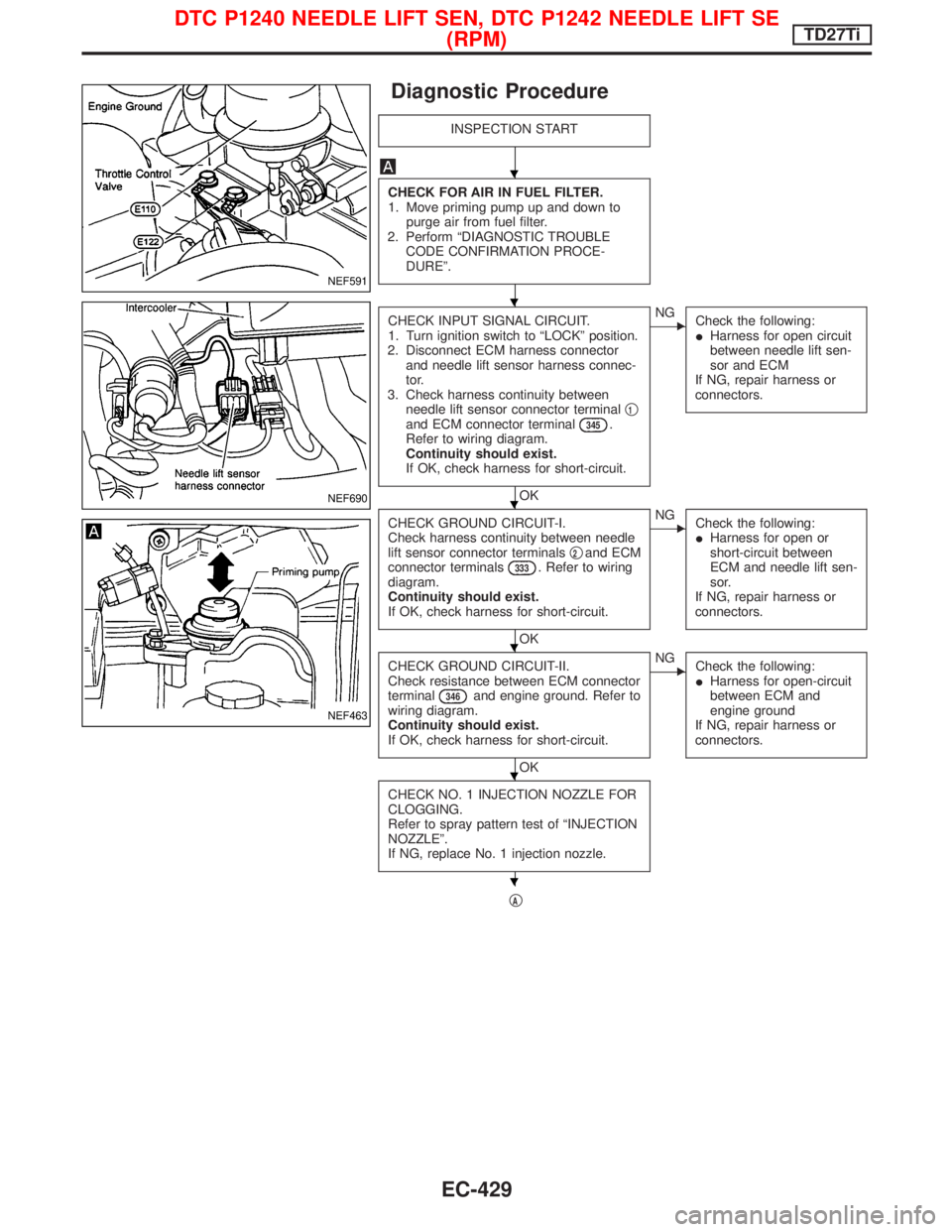
CHECK FOR AIR IN FUEL FILTER.
1. Move priming pump up and down to
purge air from fuel filter.
2. Perform ªDIAGNOSTIC TROUBLE
CODE CONFIRMATION PROCE-
DUREº.
CHECK INPUT SIGNAL CIRCUIT.
1. Turn ignition switch to ªLOCKº position.
2. Disconnect ECM harness connector
and needle lift sensor harness connec-
tor.
3. Check harness continuity between
needle lift sensor connector terminalq
1and ECM connector terminal345.
Refer to wiring diagram.
Continuity should exist.
If OK, check harness for short-circuit.
OK
ENG
Check the following:
IHarness for open circuit
between needle lift sen-
sor and ECM
If NG, repair harness or
connectors.
CHECK GROUND CIRCUIT-I.
Check harness continuity between needle
lift sensor connector terminalsq
2and ECM
connector terminals333. Refer to wiring
diagram.
Continuity should exist.
If OK, check harness for short-circuit.
OK
ENG
Check the following:
IHarness for open or
short-circuit between
ECM and needle lift sen-
sor.
If NG, repair harness or
connectors.
CHECK GROUND CIRCUIT-II.
Check resistance between ECM connector
terminal
346and engine ground. Refer to
wiring diagram.
Continuity should exist.
If OK, check harness for short-circuit.
OK
ENG
Check the following:
IHarness for open-circuit
between ECM and
engine ground
If NG, repair harness or
connectors.
CHECK NO. 1 INJECTION NOZZLE FOR
CLOGGING.
Refer to spray pattern test of ªINJECTION
NOZZLEº.
If NG, replace No. 1 injection nozzle.
qA
NEF591
NEF690
NEF463
H
H
H
H
H
H
DTC P1240 NEEDLE LIFT SEN, DTC P1242 NEEDLE LIFT SE
(RPM)TD27Ti
EC-429
Page 795 of 1767
Wiring Diagram
LHD MODELS
EGR control solenoid valve A and B
YEC159A
DTC P1404 EGR SOL/V A, DTC P1405 EGR SOL/V B/P1407
THROTTLE SOLENOID VALVETD27Ti
EC-433
Page 796 of 1767
RHD MODELS
EGR control solenoid valve A and B
YEC160A
DTC P1404 EGR SOL/V A, DTC P1405 EGR SOL/V B/P1407
THROTTLE SOLENOID VALVETD27Ti
Wiring Diagram (Cont'd)
EC-434
Page 797 of 1767
Throttle control solenoid valve
YEC161A
DTC P1404 EGR SOL/V A, DTC P1405 EGR SOL/V B/P1407
THROTTLE SOLENOID VALVETD27Ti
Wiring Diagram (Cont'd)
EC-435