Page 686 of 1767

DIAGNOSTIC TEST MODE IÐBULB CHECK
In this mode, the MALFUNCTION INDICATOR on the instrument panel should stay ON. If it remains OFF,
check the bulb. Refer to EL section (ªWARNING LAMPS/WIRING DIAGRAMº) or see EC-452.
DIAGNOSTIC TEST MODE IÐMALFUNCTION WARNING
MI Condition
ON When a malfunction is detected or the ECM's CPU is malfunctioning.
OFF No malfunction.
IThese Diagnostic Trouble Code Numbers are clarified in Diagnostic Test Mode II (SELF-DIAGNOSTIC
RESULTS).
DIAGNOSTIC TEST MODE IIÐSELF-DIAGNOSTIC RESULTS
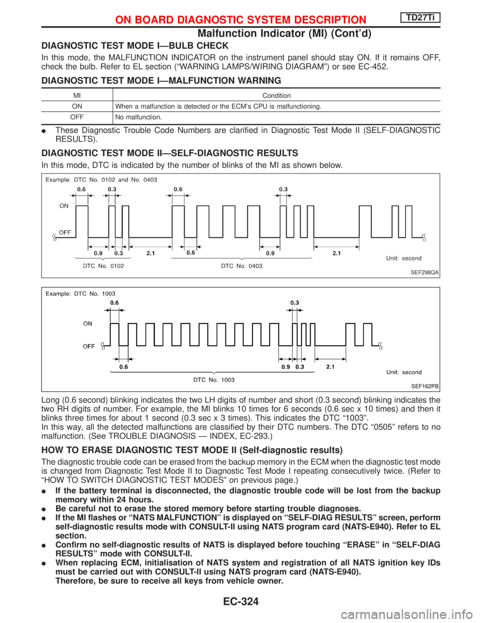
In this mode, DTC is indicated by the number of blinks of the MI as shown below.
Long (0.6 second) blinking indicates the two LH digits of number and short (0.3 second) blinking indicates the
two RH digits of number. For example, the MI blinks 10 times for 6 seconds (0.6 sec x 10 times) and then it
blinks three times for about 1 second (0.3 sec x 3 times). This indicates the DTC ª1003º.
In this way, all the detected malfunctions are classified by their DTC numbers. The DTC ª0505º refers to no
malfunction. (See TROUBLE DIAGNOSIS Ð INDEX, EC-293.)
HOW TO ERASE DIAGNOSTIC TEST MODE II (Self-diagnostic results)
The diagnostic trouble code can be erased from the backup memory in the ECM when the diagnostic test mode
is changed from Diagnostic Test Mode II to Diagnostic Test Mode I repeating consecutively twice. (Refer to
ªHOW TO SWITCH DIAGNOSTIC TEST MODESº on previous page.)
IIf the battery terminal is disconnected, the diagnostic trouble code will be lost from the backup
memory within 24 hours.
IBe careful not to erase the stored memory before starting trouble diagnoses.
IIf the MI flashes or ªNATS MALFUNCTIONº is displayed on ªSELF-DIAG RESULTSº screen, perform
self-diagnostic results mode with CONSULT-II using NATS program card (NATS-E940). Refer to EL
section.
IConfirm no self-diagnostic results of NATS is displayed before touching ªERASEº in ªSELF-DIAG
RESULTSº mode with CONSULT-II.
IWhen replacing ECM, initialisation of NATS system and registration of all NATS ignition key IDs
must be carried out with CONSULT-II using NATS program card (NATS-E940).
Therefore, be sure to receive all keys from vehicle owner.
SEF298QA
SEF162PB
ON BOARD DIAGNOSTIC SYSTEM DESCRIPTIONTD27Ti
Malfunction Indicator (MI) (Cont'd)
EC-324
Page 714 of 1767
Wiring Diagram
YEC141A
TROUBLE DIAGNOSIS FOR POWER SUPPLYTD27Ti
EC-352
Page 716 of 1767

qA
CHECK POWER SUPPLY-III.
1. Turn ignition switch to ªONº position
and then to ªLOCKº position.
2. Check voltage between ECM connector
terminals
107,108,109and engine
ground with CONSULT-II or tester.
Voltage:
After turning ignition switch to
ªLOCKº position, battery voltage
will exist for a few seconds, then
drop to approximately 0V.
NG
EOK
Go toqBªCHECK
GROUND CIRCUITº.
Case-1: Battery voltage does
not exist.
Case-2: Battery voltage exists
for more than a few
seconds.
Case-1
Case-2
EGo toªCHECK ECM
RELAYº.
CHECK HARNESS CONTINUITY
BETWEEN ECM RELAY AND ECM.
1. Disconnect ECM harness connector.
2. Disconnect ECM relay harness connec-
tor.
3. Check harness continuity between
ECM connector terminals
325and
ECM relay connector terminalq
2, and
ECM connector terminals
107,108,
109and ECM relay connector termi-
nalq
5. Refer to wiring diagram.
Continuity should exist.
If OK, check harness for short-circuit.
OK
ENG
Check the following:
IHarness connectors
M787,F66(LHD mod-
els)
IHarness for open or
short-circuit between
ECM relay connector
and ECM connector.
If NG, repair harness or
connectors.
CHECK VOLTAGE BETWEEN ECCS
RELAY AND ENGINE GROUND.
Check voltage between ECM relay con-
nector terminalsq
1,q3and engine ground
with CONSULT-II or tester.
Voltage: Battery voltage
OK
ENG
Check the following:
I20A fuse
IFuse box and battery
connections
IHarness for open or
short-circuit between
ECM relay and battery
If NG, replace fuse or
repair harness or connec-
tors.
CHECK ECM RELAY.
1. Remove ECM relay.
2. Apply 12V direct current between relay
terminalsq
1andq2.
3. Check continuity between relay termi-
nalsq
3andq5.
12V (q
1-q2) applied:
Continuity exists.
No voltage applied:
No continuity
OK
ENG
Replace ECM relay.
qB
MEC944D
MEC945D
NEF350
H
H
H
H
H
TROUBLE DIAGNOSIS FOR POWER SUPPLYTD27Ti
Diagnostic Procedure (Cont'd)
EC-354
Page 717 of 1767
qB
CHECK GROUND CIRCUIT.
1. Turn ignition switch to ªLOCKº position.
2. Disconnect ECM harness connector.
3. Check harness continuity between
ECM connector terminals
104,105,
106and engine ground. Refer to wir-
ing diagram.
Continuity should exist.
If OK, check harness for short-circuit.
OK
ENG
Check the following:
IEngine ground connec-
tions
IHarness for open or
short-circuit between
ECM and engine ground
If NG, repair harness or
connectors.
Check ECM pin terminals for damage and
check the connection of ECM harness
connector.
INSPECTION END
H
H
H
TROUBLE DIAGNOSIS FOR POWER SUPPLYTD27Ti
Diagnostic Procedure (Cont'd)
EC-355
Page 719 of 1767
Wiring Diagram
LHD MODELS
YEC142A
DTC P0100 MASS AIR FLOW SENTD27Ti
EC-357
Page 720 of 1767
RHD MODELS
YEC143A
DTC P0100 MASS AIR FLOW SENTD27Ti
Wiring Diagram (Cont'd)
EC-358
Page 721 of 1767

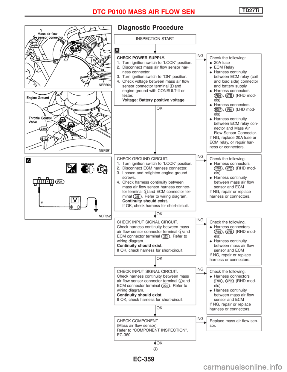
Diagnostic Procedure
INSPECTION START
CHECK POWER SUPPLY.
1. Turn ignition switch to ªLOCKº position.
2. Disconnect mass air flow sensor har-
ness connector.
3. Turn ignition switch to ªONº position.
4. Check voltage between mass air flow
sensor connector terminalq
2and
engine ground with CONSULT-II or
tester.
Voltage: Battery positive voltage
OK
ENG
Check the following:
I20A fuse
IECM Relay
IHarness continuity
between ECM relay (coil
and load side) connector
and battery supply
IHarness connectors
F100,M755(RHD mod-
els)
IHarness connectors
M787,F66(LHD mod-
els)
IHarness continuity
between ECM relay con-
nector and Mass Air
Flow Sensor Connector.
If NG, replace 20A fuse or
ECM relay, or repair har-
ness or connectors.
CHECK GROUND CIRCUIT.
1. Turn ignition switch to ªLOCKº position.
2. Disconnect ECM harness connector.
3. Loosen and retighten engine ground
screws.
4. Check harness continuity between
mass air flow sensor harness connec-
tor terminalq
3and ECM connector ter-
minal218. Refer to wiring diagram.
Continuity should exist.
If OK, check harness for short-circuit.
OK
ENG
Check the following.
IHarness connectors
F100,M755(RHD mod-
els)
IHarness continuity
between mass air flow
sensor and ECM
If NG, repair or replace
harness or connectors.
CHECK INPUT SIGNAL CIRCUIT.
Check harness continuity between mass
air flow sensor connector terminalq
4and
ECM connector terminal223. Refer to
wiring diagram.
Continuity should exist.
If OK, check harness for short-circuit.
OK
ENG
Check the following.
IHarness connectors
F100,M755(RHD mod-
els)
IHarness continuity
between mass air flow
sensor and ECM
If NG, repair or replace
harness or connectors.
CHECK INPUT SIGNAL CIRCUIT.
Check harness continuity between mass
air flow sensor connector terminalq
5and
ECM connector terminal224. Refer to
wiring diagram.
Continuity should exist.
If OK, check harness for short-circuit.
OK
ENG
Check the following.
IHarness connectors
F100,M755(RHD mod-
els)
IHarness continuity
between mass air flow
sensor and ECM
If NG, repair or replace
harness or connectors.
CHECK COMPONENT
(Mass air flow sensor).
Refer to ªCOMPONENT INSPECTIONº,
EC-360.
OK
ENG
Replace mass air flow sen-
sor.
qA
NEF664
NEF591
NEF352
H
H
H
H
H
H
DTC P0100 MASS AIR FLOW SENTD27Ti
EC-359
Page 724 of 1767
Wiring Diagram
YEC144A
DTC P0115 COOLANT TEMP SENTD27Ti
EC-362