Page 621 of 1767
Wiring Diagram
LHD MODELS
YEC198A
HEAT UP SWITCHZD30DDTi
EC-259
Page 623 of 1767

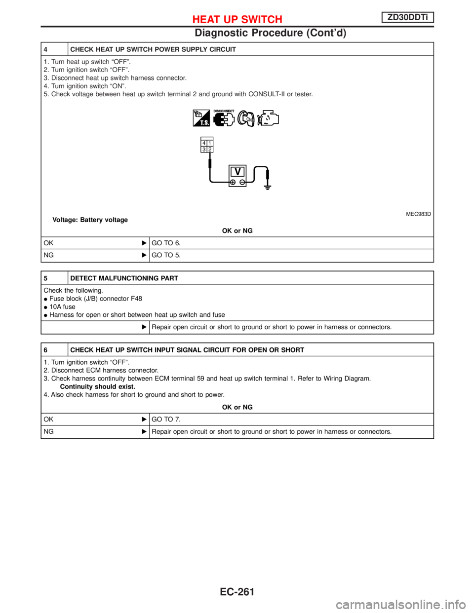
4 CHECK HEAT UP SWITCH POWER SUPPLY CIRCUIT
1. Turn heat up switch ªOFFº.
2. Turn ignition switch ªOFFº.
3. Disconnect heat up switch harness connector.
4. Turn ignition switch ªONº.
5. Check voltage between heat up switch terminal 2 and ground with CONSULT-II or tester.
MEC983DVoltage: Battery voltage
OK or NG
OKEGO TO 6.
NGEGO TO 5.
5 DETECT MALFUNCTIONING PART
Check the following.
IFuse block (J/B) connector F48
I10A fuse
IHarness for open or short between heat up switch and fuse
ERepair open circuit or short to ground or short to power in harness or connectors.
6 CHECK HEAT UP SWITCH INPUT SIGNAL CIRCUIT FOR OPEN OR SHORT
1. Turn ignition switch ªOFFº.
2. Disconnect ECM harness connector.
3. Check harness continuity between ECM terminal 59 and heat up switch terminal 1. Refer to Wiring Diagram.
Continuity should exist.
4. Also check harness for short to ground and short to power.
OK or NG
OKEGO TO 7.
NGERepair open circuit or short to ground or short to power in harness or connectors.
HEAT UP SWITCHZD30DDTi
Diagnostic Procedure (Cont'd)
EC-261
Page 627 of 1767
Wiring Diagram
YEC199A
SWIRL CONTROL VALVE CONTROL SOLENOID VALVEZD30DDTi
EC-265
Page 633 of 1767

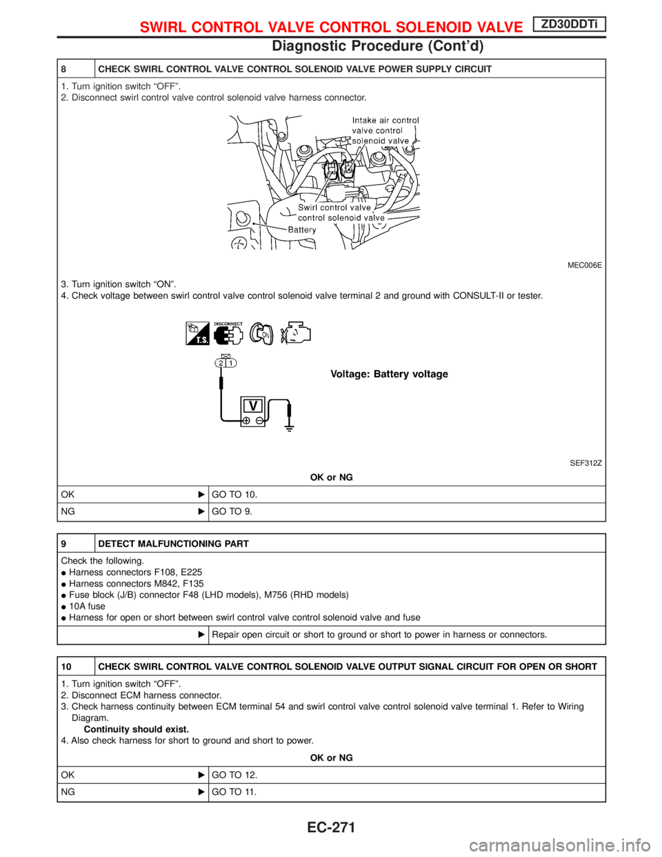
8 CHECK SWIRL CONTROL VALVE CONTROL SOLENOID VALVE POWER SUPPLY CIRCUIT
1. Turn ignition switch ªOFFº.
2. Disconnect swirl control valve control solenoid valve harness connector.
MEC006E
3. Turn ignition switch ªONº.
4. Check voltage between swirl control valve control solenoid valve terminal 2 and ground with CONSULT-II or tester.
SEF312Z
OK or NG
OKEGO TO 10.
NGEGO TO 9.
9 DETECT MALFUNCTIONING PART
Check the following.
IHarness connectors F108, E225
IHarness connectors M842, F135
IFuse block (J/B) connector F48 (LHD models), M756 (RHD models)
I10A fuse
IHarness for open or short between swirl control valve control solenoid valve and fuse
ERepair open circuit or short to ground or short to power in harness or connectors.
10 CHECK SWIRL CONTROL VALVE CONTROL SOLENOID VALVE OUTPUT SIGNAL CIRCUIT FOR OPEN OR SHORT
1. Turn ignition switch ªOFFº.
2. Disconnect ECM harness connector.
3. Check harness continuity between ECM terminal 54 and swirl control valve control solenoid valve terminal 1. Refer to Wiring
Diagram.
Continuity should exist.
4. Also check harness for short to ground and short to power.
OK or NG
OKEGO TO 12.
NGEGO TO 11.
SWIRL CONTROL VALVE CONTROL SOLENOID VALVEZD30DDTi
Diagnostic Procedure (Cont'd)
EC-271
Page 636 of 1767
Wiring Diagram
YEC200A
INTAKE AIR CONTROL VALVE CONTROL SOLENOID
VA LV EZD30DDTi
EC-274
Page 640 of 1767

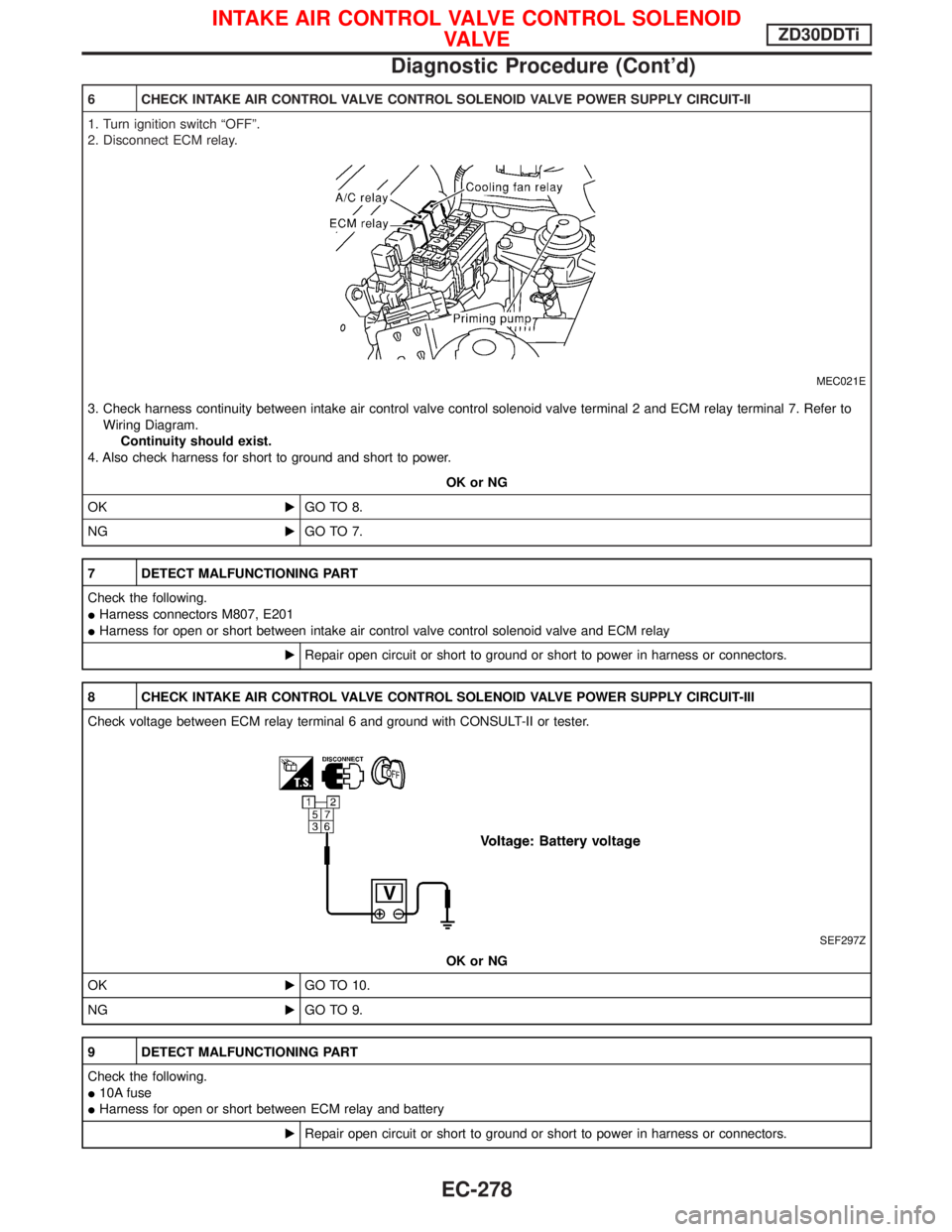
6 CHECK INTAKE AIR CONTROL VALVE CONTROL SOLENOID VALVE POWER SUPPLY CIRCUIT-II
1. Turn ignition switch ªOFFº.
2. Disconnect ECM relay.
MEC021E
3. Check harness continuity between intake air control valve control solenoid valve terminal 2 and ECM relay terminal 7. Refer to
Wiring Diagram.
Continuity should exist.
4. Also check harness for short to ground and short to power.
OK or NG
OKEGO TO 8.
NGEGO TO 7.
7 DETECT MALFUNCTIONING PART
Check the following.
IHarness connectors M807, E201
IHarness for open or short between intake air control valve control solenoid valve and ECM relay
ERepair open circuit or short to ground or short to power in harness or connectors.
8 CHECK INTAKE AIR CONTROL VALVE CONTROL SOLENOID VALVE POWER SUPPLY CIRCUIT-III
Check voltage between ECM relay terminal 6 and ground with CONSULT-II or tester.
SEF297Z
OK or NG
OKEGO TO 10.
NGEGO TO 9.
9 DETECT MALFUNCTIONING PART
Check the following.
I10A fuse
IHarness for open or short between ECM relay and battery
ERepair open circuit or short to ground or short to power in harness or connectors.
INTAKE AIR CONTROL VALVE CONTROL SOLENOID
VA LV EZD30DDTi
Diagnostic Procedure (Cont'd)
EC-278
Page 641 of 1767

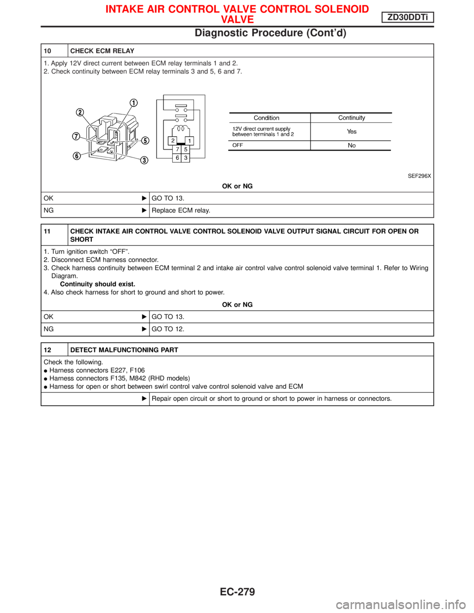
10 CHECK ECM RELAY
1. Apply 12V direct current between ECM relay terminals 1 and 2.
2. Check continuity between ECM relay terminals 3 and 5, 6 and 7.
SEF296X
OK or NG
OKEGO TO 13.
NGEReplace ECM relay.
11 CHECK INTAKE AIR CONTROL VALVE CONTROL SOLENOID VALVE OUTPUT SIGNAL CIRCUIT FOR OPEN OR
SHORT
1. Turn ignition switch ªOFFº.
2. Disconnect ECM harness connector.
3. Check harness continuity between ECM terminal 2 and intake air control valve control solenoid valve terminal 1. Refer to Wiring
Diagram.
Continuity should exist.
4. Also check harness for short to ground and short to power.
OK or NG
OKEGO TO 13.
NGEGO TO 12.
12 DETECT MALFUNCTIONING PART
Check the following.
IHarness connectors E227, F106
IHarness connectors F135, M842 (RHD models)
IHarness for open or short between swirl control valve control solenoid valve and ECM
ERepair open circuit or short to ground or short to power in harness or connectors.
INTAKE AIR CONTROL VALVE CONTROL SOLENOID
VA LV EZD30DDTi
Diagnostic Procedure (Cont'd)
EC-279
Page 645 of 1767
Wiring Diagram
YEC201A
VARIABLE NOZZLE TURBOCHARGER CONTROL
SOLENOID VALVEZD30DDTi
EC-283