Page 569 of 1767
3 DETECT MALFUNCTIONING PART
Check the following.
IFuse block (J/B) connector F114 (LHD models), M835 (RHD models)
I15A fuse
IHarness for open and short between stop lamp switch and fuse
ERepair open circuit or short to ground or short to power in harness or connectors.
4 CHECK STOP LAMP SWITCH INPUT SIGNAL CIRCUIT FOR OPEN AND SHORT
1. Turn ignition switch ªOFFº.
2. Disconnect ECM harness connector.
3. Disconnect stop lamp switch harness connector.
MEC027E
4. Check harness continuity between ECM terminal 17 and stop lamp switch terminal 2. Refer to Wiring Diagram.
Continuity should exist.
5. Also check harness for short to ground and short to power.
OK or NG
OKEGO TO 5.
NGERepair open circuit or short to ground or short to power in harness or connectors.
DTC 0807 ECM 14ZD30DDTi
Diagnostic Procedure (Cont'd)
EC-207
Page 572 of 1767
Wiring Diagram
YEC190A
DTC 0902 ECM RLYZD30DDTi
EC-210
Page 573 of 1767
Diagnostic Procedure
1 CHECK ECM POWER SUPPLY CIRCUIT
1. Turn ignition switch ªOFFº.
2. Disconnect ECM relay.
MEC021E
3. Check voltage between ECM relay terminals 2, 3 and ground with CONSULT-II or tester.
MEC978DVoltage: Battery voltage
OK or NG
OKEGO TO 3.
NGEGO TO 2.
2 DETECT MALFUNCTIONING PART
Check the following.
1. 10A fuse
2. 15A fuse
3. Harness for open and short between ECM relay and battery
ERepair open circuit or short to ground or short to power in harness or connectors.
3 CHECK ECM INPUT SIGNAL CIRCUIT FOR OPEN AND SHORT
1. Turn ignition switch ªOFFº.
2. Disconnect ECM harness connector.
3. Check harness continuity between ECM terminals 56, 61, 116 and ECM relay terminal 5. Refer to Wiring Diagram.
Continuity should exist.
4. Also check harness for short to ground and short to power.
OK or NG
OKEGO TO 5.
NGEGO TO 4.
DTC 0902 ECM RLYZD30DDTi
EC-211
Page 574 of 1767

4 DETECT MALFUNCTIONING PART
Check the following.
IHarness connectors M787, F66 (LHD models)
IHarness for open or short between ECM and ECM relay
ERepair open circuit or short to ground or short to power in harness or connectors.
5 CHECK ECM OUTPUT SIGNAL CIRCUIT FOR OPEN AND SHORT
1. Check harness continuity between ECM terminal 4 and ECM relay terminal 1. Refer to Wiring Diagram.
Continuity should exist.
2. Also check harness for short to ground and short to power.
OK or NG
OKEGO TO 7.
NGEGO TO 6.
6 DETECT MALFUNCTIONING PART
Check the following.
IHarness connectors M787, F66 (LHD models)
IHarness for open or short between ECM and ECM relay
ERepair open circuit or short to ground or short to power in harness or connectors.
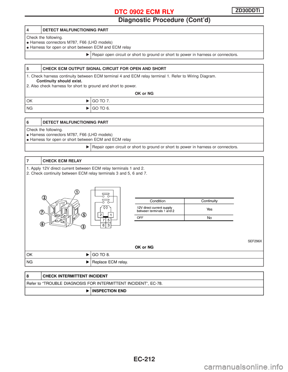
7 CHECK ECM RELAY
1. Apply 12V direct current between ECM relay terminals 1 and 2.
2. Check continuity between ECM relay terminals 3 and 5, 6 and 7.
SEF296X
OK or NG
OKEGO TO 8.
NGEReplace ECM relay.
8 CHECK INTERMITTENT INCIDENT
Refer to ªTROUBLE DIAGNOSIS FOR INTERMITTENT INCIDENTº, EC-78.
EINSPECTION END
DTC 0902 ECM RLYZD30DDTi
Diagnostic Procedure (Cont'd)
EC-212
Page 579 of 1767
Wiring Diagram
LHD MODELS
YEC191A
DTC 0905 TURBO PRESSUREZD30DDTi
EC-217
Page 580 of 1767
RHD MODELS
YEC192A
DTC 0905 TURBO PRESSUREZD30DDTi
Wiring Diagram (Cont'd)
EC-218
Page 581 of 1767

Diagnostic Procedure
1 CHECK CHARGE AIR PRESSURE SENSOR POWER SUPPLY CIRCUIT
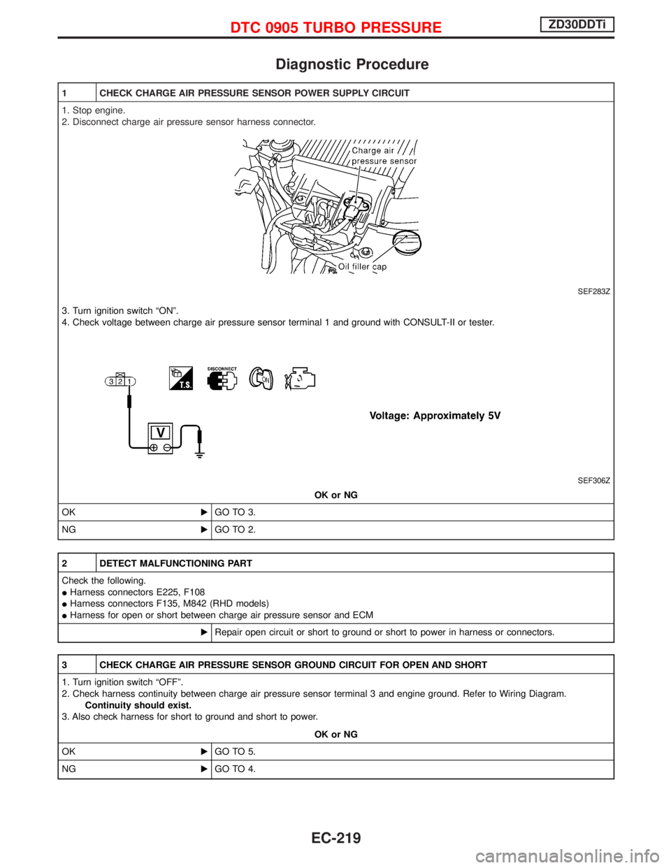
1. Stop engine.
2. Disconnect charge air pressure sensor harness connector.
SEF283Z
3. Turn ignition switch ªONº.
4. Check voltage between charge air pressure sensor terminal 1 and ground with CONSULT-II or tester.
SEF306Z
OK or NG
OKEGO TO 3.
NGEGO TO 2.
2 DETECT MALFUNCTIONING PART
Check the following.
IHarness connectors E225, F108
IHarness connectors F135, M842 (RHD models)
IHarness for open or short between charge air pressure sensor and ECM
ERepair open circuit or short to ground or short to power in harness or connectors.
3 CHECK CHARGE AIR PRESSURE SENSOR GROUND CIRCUIT FOR OPEN AND SHORT
1. Turn ignition switch ªOFFº.
2. Check harness continuity between charge air pressure sensor terminal 3 and engine ground. Refer to Wiring Diagram.
Continuity should exist.
3. Also check harness for short to ground and short to power.
OK or NG
OKEGO TO 5.
NGEGO TO 4.
DTC 0905 TURBO PRESSUREZD30DDTi
EC-219
Page 582 of 1767

4 DETECT MALFUNCTIONING PART
Check the following.
IHarness connectors E225, F108
IHarness connectors F135, M852 (RHD models)
IHarness for open or short between ECM and charge air pressure sensor
ERepair open circuit or short to ground or short to power in harness or connectors.
5 CHECK CHARGE AIR PRESSURE SENSOR INPUT SIGNAL CIRCUIT FOR OPEN AND SHORT
1. Disconnect ECM harness connector.
2. Check harness continuity between ECM terminal 46 and charge air pressure sensor terminal 2. Refer to Wiring Diagram.
Continuity should exist.
3. Also check harness for short to ground and short to power.
OK or NG
OKEGO TO 7.
NGEGO TO 6.
6 DETECT MALFUNCTIONING PART
Check the following.
IHarness connectors E225, F108
IHarness connectors F135, M842 (RHD models)
IHarness for open or short between charge air pressure sensor and ECM
ERepair open circuit or short to ground or short to power in harness or connectors.
7 CHECK CHARGE AIR PRESSURE SENSOR
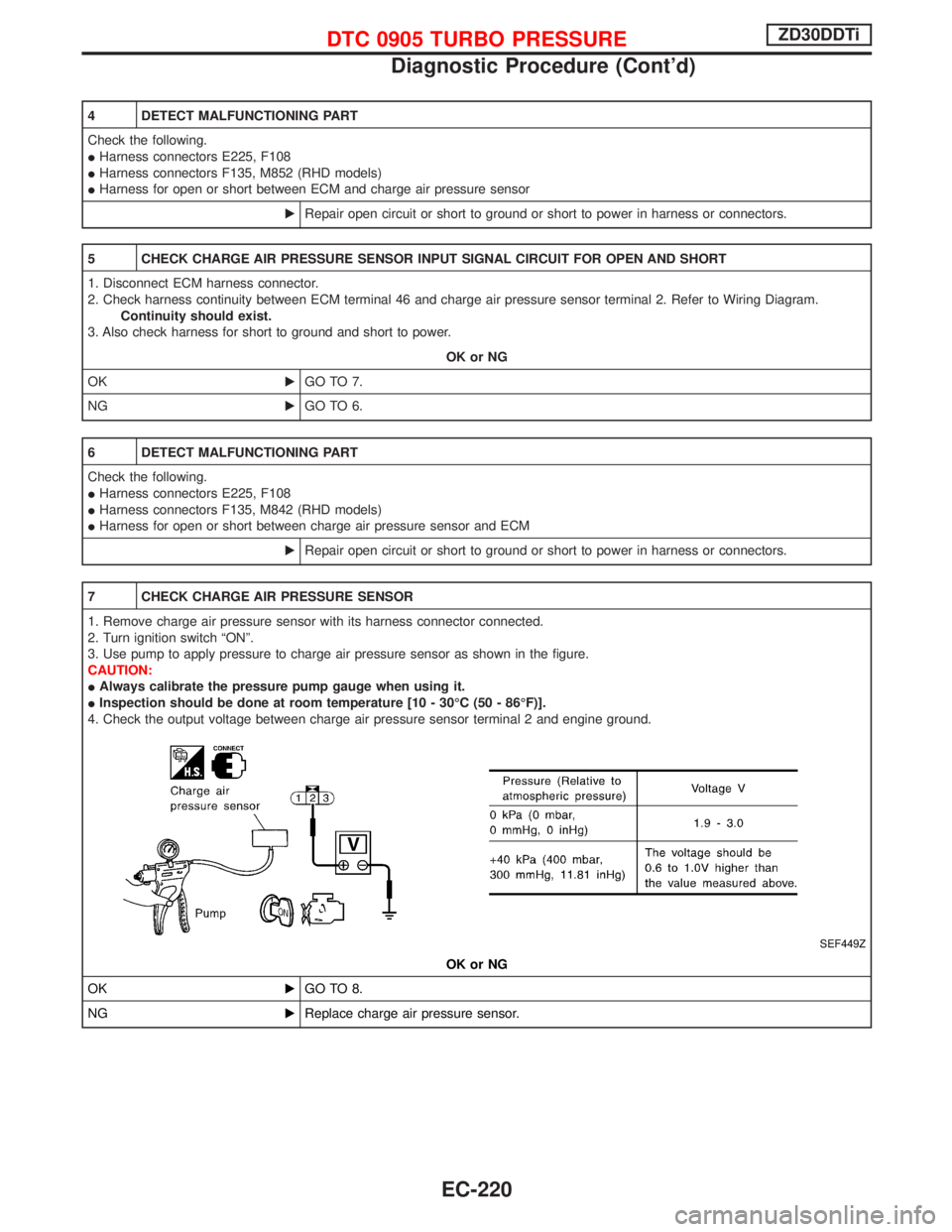
1. Remove charge air pressure sensor with its harness connector connected.
2. Turn ignition switch ªONº.
3. Use pump to apply pressure to charge air pressure sensor as shown in the figure.
CAUTION:
IAlways calibrate the pressure pump gauge when using it.
IInspection should be done at room temperature [10 - 30ÉC (50 - 86ÉF)].
4. Check the output voltage between charge air pressure sensor terminal 2 and engine ground.
SEF449Z
OK or NG
OKEGO TO 8.
NGEReplace charge air pressure sensor.
DTC 0905 TURBO PRESSUREZD30DDTi
Diagnostic Procedure (Cont'd)
EC-220