Page 649 of 1767

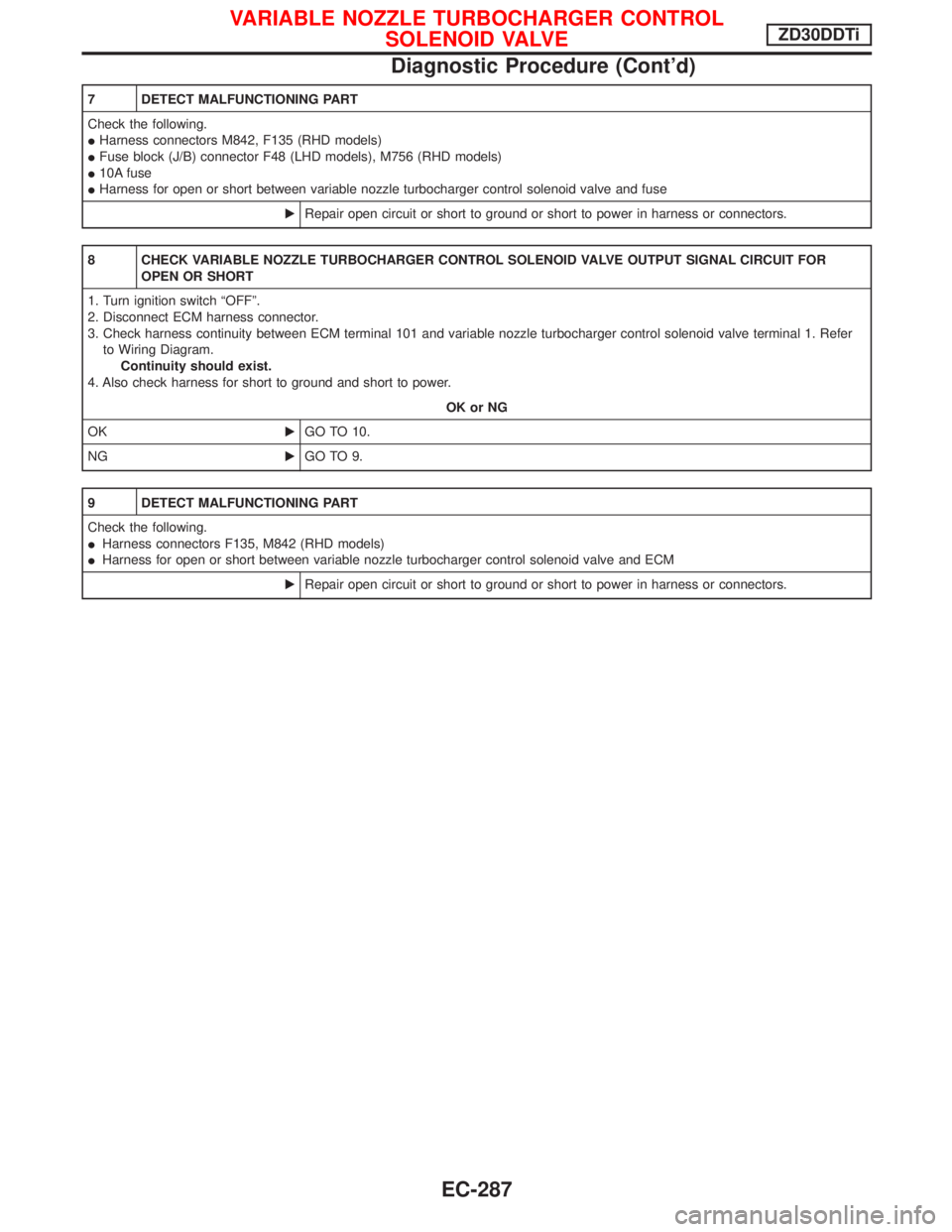
7 DETECT MALFUNCTIONING PART
Check the following.
IHarness connectors M842, F135 (RHD models)
IFuse block (J/B) connector F48 (LHD models), M756 (RHD models)
I10A fuse
IHarness for open or short between variable nozzle turbocharger control solenoid valve and fuse
ERepair open circuit or short to ground or short to power in harness or connectors.
8 CHECK VARIABLE NOZZLE TURBOCHARGER CONTROL SOLENOID VALVE OUTPUT SIGNAL CIRCUIT FOR
OPEN OR SHORT
1. Turn ignition switch ªOFFº.
2. Disconnect ECM harness connector.
3. Check harness continuity between ECM terminal 101 and variable nozzle turbocharger control solenoid valve terminal 1. Refer
to Wiring Diagram.
Continuity should exist.
4. Also check harness for short to ground and short to power.
OK or NG
OKEGO TO 10.
NGEGO TO 9.
9 DETECT MALFUNCTIONING PART
Check the following.
IHarness connectors F135, M842 (RHD models)
IHarness for open or short between variable nozzle turbocharger control solenoid valve and ECM
ERepair open circuit or short to ground or short to power in harness or connectors.
VARIABLE NOZZLE TURBOCHARGER CONTROL
SOLENOID VALVEZD30DDTi
Diagnostic Procedure (Cont'd)
EC-287
Page 651 of 1767
Wiring Diagram
LHD MODELS
YEC202A
AIR CONDITIONER CONTROLZD30DDTi
EC-289
Page 652 of 1767
RHD MODELS
YEC203A
AIR CONDITIONER CONTROLZD30DDTi
Wiring Diagram (Cont'd)
EC-290
Page 653 of 1767
Wiring Diagram
YEC204A
MI (MIL) & DATA LINK CONNECTORSZD30DDTi
EC-291
Page 664 of 1767
Circuit Diagram
YEC140A
ENGINE AND EMISSION CONTROL OVERALL SYSTEMTD27Ti
EC-302
Page 665 of 1767
System Diagram
YEC235A
ENGINE AND EMISSION CONTROL OVERALL SYSTEMTD27Ti
EC-303
Page 666 of 1767
Vacuum Hose Drawing
q1Throttle body control valve actuator
to throttle body control solenoid
valve
q
2EGR valve to 3-way connector
q
3EGRC-solenoid valve A to 3-way
connector-1q
4EGRC-solenoid valve B to 3-way
connector-1
q
5Throttle body control solenoid
valve to 2-way connector-2
q
6EGRC-solenoid valve A to 3-way
connector-2q
7Tube to 3-way connector-2
q
8Tube to vacuum pump
q
9Tube to brake booster
Refer to ªSystem Diagramº, on previous page for vacuum control system
NEF759
ENGINE AND EMISSION CONTROL OVERALL SYSTEMTD27Ti
EC-304
Page 684 of 1767

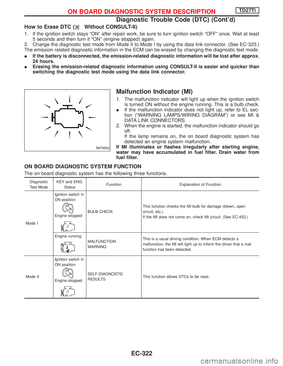
How to Erase DTC (Without CONSULT-II)
1. If the ignition switch stays ªONº after repair work, be sure to turn ignition switch ªOFFº once. Wait at least
5 seconds and then turn it ªONº (engine stopped) again.
2. Change the diagnostic test mode from Mode II to Mode I by using the data link connector. (See EC-323.)
The emission related diagnostic information in the ECM can be erased by changing the diagnostic test mode.
IIf the battery is disconnected, the emission-related diagnostic information will be lost after approx.
24 hours.
IErasing the emission-related diagnostic information using CONSULT-II is easier and quicker than
switching the diagnostic test mode using the data link connector.
Malfunction Indicator (MI)
1. The malfunction indicator will light up when the ignition switch
is turned ON without the engine running. This is a bulb check.
IIf the malfunction indicator does not light up, refer to EL sec-
tion (ªWARNING LAMPS/WIRING DIAGRAMº) or see MI &
DATA LINK CONNECTORS.
2. When the engine is started, the malfunction indicator should go
off.
If the lamp remains on, the on board diagnostic system has
detected an engine system malfunction.
If MI illuminates or flashes irregularly after starting engine,
water may have accumulated in fuel filter. Drain water from
fuel filter.
ON BOARD DIAGNOSTIC SYSTEM FUNCTION
The on board diagnostic system has the following three functions.
Diagnostic
Test ModeKEY and ENG.
StatusFunction Explanation of Function
Mode IIgnition switch in
ON position
Engine stoppedBULB CHECKThis function checks the MI bulb for damage (blown, open
circuit, etc.).
If the MI does not come on, check MI circuit. (See EC-452.)
Engine running
MALFUNCTION
WARNINGThis is a usual driving condition. When ECM detects a
malfunction, the MI will light up to inform the driver that a mal-
function has been detected.
Mode IIIgnition switch in
ON position
Engine stopped
SELF-DIAGNOSTIC
RESULTSThis function allows DTCs to be read.
SAT652J
ON BOARD DIAGNOSTIC SYSTEM DESCRIPTIONTD27Ti
Diagnostic Trouble Code (DTC) (Cont'd)
EC-322