Page 606 of 1767

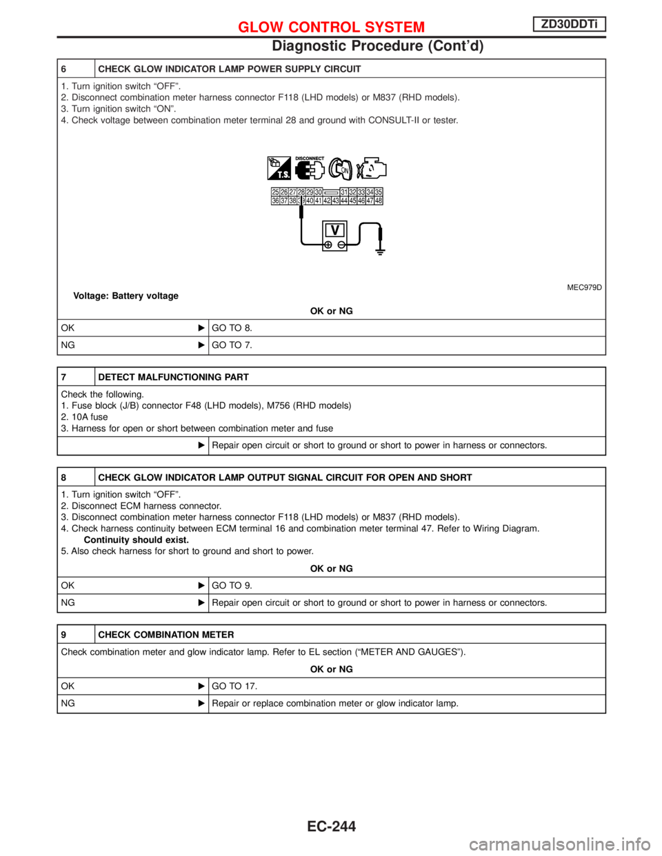
6 CHECK GLOW INDICATOR LAMP POWER SUPPLY CIRCUIT
1. Turn ignition switch ªOFFº.
2. Disconnect combination meter harness connector F118 (LHD models) or M837 (RHD models).
3. Turn ignition switch ªONº.
4. Check voltage between combination meter terminal 28 and ground with CONSULT-II or tester.
MEC979DVoltage: Battery voltage
OK or NG
OKEGO TO 8.
NGEGO TO 7.
7 DETECT MALFUNCTIONING PART
Check the following.
1. Fuse block (J/B) connector F48 (LHD models), M756 (RHD models)
2. 10A fuse
3. Harness for open or short between combination meter and fuse
ERepair open circuit or short to ground or short to power in harness or connectors.
8 CHECK GLOW INDICATOR LAMP OUTPUT SIGNAL CIRCUIT FOR OPEN AND SHORT
1. Turn ignition switch ªOFFº.
2. Disconnect ECM harness connector.
3. Disconnect combination meter harness connector F118 (LHD models) or M837 (RHD models).
4. Check harness continuity between ECM terminal 16 and combination meter terminal 47. Refer to Wiring Diagram.
Continuity should exist.
5. Also check harness for short to ground and short to power.
OK or NG
OKEGO TO 9.
NGERepair open circuit or short to ground or short to power in harness or connectors.
9 CHECK COMBINATION METER
Check combination meter and glow indicator lamp. Refer to EL section (ªMETER AND GAUGESº).
OK or NG
OKEGO TO 17.
NGERepair or replace combination meter or glow indicator lamp.
GLOW CONTROL SYSTEMZD30DDTi
Diagnostic Procedure (Cont'd)
EC-244
Page 607 of 1767
10 CHECK GLOW RELAY POWER SUPPLY CIRCUIT
1. Turn ignition switch ªOFFº.
2. Disconnect glow relay.
MEC004E
3. Check voltage between glow relay terminals 2, 5 and ground with CONSULT-II or tester.
MEC980DVoltage: Battery voltage
OK or NG
OKEGO TO 12.
NGEGO TO 11.
11 DETECT MALFUNCTIONING PART
Check the following.
I80A fusible link
I10A fuse
IHarness for open or short between glow relay and battery
ERepair harness or connectors.
12 CHECK GLOW RELAY OUTPUT SIGNAL CIRCUIT FOR OPEN AND SHORT
1. Disconnect ECM harness connector.
2. Check harness continuity between ECM terminal 111 and glow relay terminal 1. Refer to Wiring Diagram.
Continuity should exist.
3. Also check harness for short to ground and short to power.
OK or NG
OKEGO TO 14.
NGEGO TO 13.
GLOW CONTROL SYSTEMZD30DDTi
Diagnostic Procedure (Cont'd)
EC-245
Page 608 of 1767

13 DETECT MALFUNCTIONING PART
Check the following.
IHarness connectors M787, F66 (LHD models)
IHarness for open or short between glow relay and ECM
ERepair open circuit or short to ground or short to power in harness or connectors.
14 CHECK HARNESS CONTINUITY BETWEEN GLOW RELAY AND GLOW PLUG FOR OPEN AND SHORT
1. Disconnect glow plug harness connector.
2. Check harness continuity between glow relay terminal 3 and glow plug harness connector. Refer to Wiring Diagram.
Continuity should exist.
3. Also check harness for short to ground and short to power.
OK or NG
OKEGO TO 16.
NGEGO TO 15.
15 DETECT MALFUNCTIONING PART
Check the following.
IHarness connectors M45, E202
IHarness connectors E230, E241
IHarness for open or short between glow relay and glow plug
ERepair open circuit or short to ground or short to power in harness or connectors.
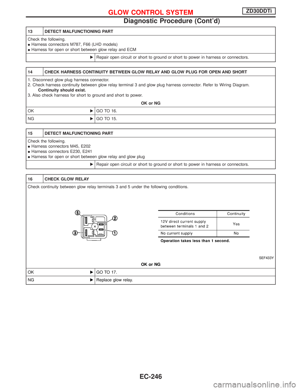
16 CHECK GLOW RELAY
Check continuity between glow relay terminals 3 and 5 under the following conditions.
SEF433Y
OK or NG
OKEGO TO 17.
NGEReplace glow relay.
GLOW CONTROL SYSTEMZD30DDTi
Diagnostic Procedure (Cont'd)
EC-246
Page 610 of 1767
Wiring Diagram
YEC196A
START SIGNALZD30DDTi
EC-248
Page 611 of 1767

Diagnostic Procedure
1 CHECK START SIGNAL OVERALL FUNCTION
With CONSULT-II
1. Turn ignition switch ªONº.
2. Check ªSTART SIGNALº in ªDATA MONITORº mode with CONSULT-II under the following conditions.
SEF604X
Without CONSULT-II
Check voltage between ECM terminal 20 and ground under the following conditions.
SEF415Y
OK or NG
OKEINSPECTION END
NGEGO TO 2.
2 CHECK START SIGNAL INPUT SIGNAL CIRCUIT
1. Turn ignition switch ªOFFº.
2. Disconnect ECM harness connector and ignition switch harness connector.
3. Check harness continuity between ECM terminal 20 and ignition switch terminal 5. Refer to Wiring Diagram.
Continuity should exist.
4. Also check harness for short to ground and short to power.
OK or NG
OKEGO TO 4.
NGEGO TO 3.
3 DETECT MALFUNCTIONING PART
Check the following.
IHarness connectors M787, F66 (LHD models)
IHarness for open or short between ECM and ignition switch
ERepair open circuit or short to ground or short to power in harness or connectors.
START SIGNALZD30DDTi
EC-249
Page 614 of 1767
Wiring Diagram
YEC197A
PARK/NEUTRAL POSITION (PNP) SWITCHZD30DDTi
EC-252
Page 616 of 1767

2 CHECK PNP SWITCH GROUND CIRCUIT FOR OPEN AND SHORT
1. Turn ignition switch ªOFFº.
2. Disconnect park/neutral position (PNP) switch harness connector.
MEC029E
3. Check harness continuity between PNP switch terminal 2 and body ground. Refer to Wiring Diagram.
Continuity should exist.
4. Also check harness for short to ground and short to power.
OK or NG
OKEGO TO 3.
NGERepair open circuit or short to ground or short to power in harness or connectors.
3 CHECK PNP SWITCH INPUT SIGNAL CIRCUIT FOR OPEN AND SHORT
1. Disconnect ECM harness connector.
2. Check harness continuity between ECM terminal 22 and PNP switch terminal 1. Refer to Wiring Diagram.
Continuity should exist.
3. Also check harness for short to ground and short to power.
OK or NG
OKEGO TO 5.
NGEGO TO 4.
4 DETECT MALFUNCTIONING PART
Check the following.
IHarness connectors M842, F135 (RHD models)
IHarness connectors F108, E225
IHarness for open or short between PNP switch and ECM
ERepair open circuit or short to ground or short to power in harness or connectors.
5 CHECK PARK/NEUTRAL POSITION SWITCH
Refer to MT section (ªPOSITION SWITCH CHECKº).
OK or NG
OKEGO TO 6.
NGEReplace park/neutral position switch.
PARK/NEUTRAL POSITION (PNP) SWITCHZD30DDTi
Diagnostic Procedure (Cont'd)
EC-254
Page 619 of 1767

4 CHECK PNP RELAY INPUT SIGNAL CIRCUIT FOR OPEN OR SHORT
1. Turn ignition switch ªOFFº.
2. Disconnect park/neutral position switch and park/neutral position relay harness connectors.
3. Check harness continuity between PNP switch terminal 2 and PNP relay terminals 2. Refer to wiring diagram.
Continuity should exist.
4. Also check harness for short to ground and short to power.
OK or NG
OKEGO TO 5.
NGERepair open circuit or short to ground or short to power in harness or connectors.
5 CHECK GROUND CIRCUIT
1. Disconnect PNP relay harness connector.
2. Check continuity between PNP relay terminal 1 and ground. Refer to wiring diagram.
Continuity should exist.
3. Also check harness for short to power.
OK or NG
OKEGO TO 6.
NGERepair open circuit or short to ground or short to power in harness or connectors.
6 CHECK ECM INPUT SIGNAL CIRCUIT
1. Disconnect ECM harness connector and PNP relay harness connector.
2. Check continuity between ECM terminal 22 and PNP relay terminal 7. Refer to wiring diagram.
Continuity should exist.
3. Also check harness for short to ground or short to power.
OK or NG
OKEGO TO 8.
NGEGO TO 7.
7 DETECT MALFUNCTIONING PART
Check the following.
IHarness connectors F93, M788 (LHD models)
IHarness for open or short between PNP relay and ECM
ERepair open circuit or short to ground or short to power in harness or connectors.
8 CHECK PARK/NEUTRAL POSITION (PNP) SWITCH
Refer to ªTROUBLE DIAGNOSIS FOR NON-DETECTABLE ITEMSº in AT section.
OK or NG
OKEGO TO 9.
NGEReplace park/neutral position (PNP) switch.
9 CHECK INTERMITTENT INCIDENT
Perform ªTROUBLE DIAGNOSIS FOR INTERMITTENT INCIDENTº, EC-78.
EINSPECTION END
PARK/NEUTRAL POSITION (PNP) SWITCHZD30DDTi
Diagnostic Procedure (Cont'd)
EC-257