Page 725 of 1767

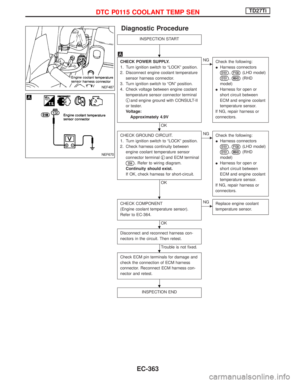
Diagnostic Procedure
INSPECTION START
CHECK POWER SUPPLY.
1. Turn ignition switch to ªLOCKº position.
2. Disconnect engine coolant temperature
sensor harness connector.
3. Turn ignition switch to ªONº position.
4. Check voltage between engine coolant
temperature sensor connector terminal
q
1and engine ground with CONSULT-II
or tester.
Voltage:
Approximately 4.9V
OK
ENG
Check the following:
IHarness connectors
E151,F138(LHD model)
E151,M843(RHD
model)
IHarness for open or
short circuit between
ECM and engine coolant
temperature sensor.
If NG, repair harness or
connectors.
CHECK GROUND CIRCUIT.
1. Turn ignition switch to ªLOCKº position.
2. Check harness continuity between
engine coolant temperature sensor
connector terminalq
2and ECM terminal
334. Refer to wiring diagram.
Continuity should exist.
If OK, check harness for short-circuit.
OK
ENG
Check the following:
IHarness connectors
E151,F138(LHD model)
E151,M843(RHD
model)
IHarness for open or
short circuit between
ECM and engine coolant
temperature sensor.
If NG, repair harness or
connectors.
CHECK COMPONENT
(Engine coolant temperature sensor).
Refer to EC-364.
OK
ENG
Replace engine coolant
temperature sensor.
Disconnect and reconnect harness con-
nectors in the circuit. Then retest.
Trouble is not fixed.
Check ECM pin terminals for damage and
check the connection of ECM harness
connector. Reconnect ECM harness con-
nector and retest.
INSPECTION END
NEF487
NEF670
H
H
H
H
H
H
DTC P0115 COOLANT TEMP SENTD27Ti
EC-363
Page 729 of 1767
Wiring Diagram
YEC145A
DTC P0120 ACCEL POS SENSORTD27Ti
EC-367
Page 730 of 1767

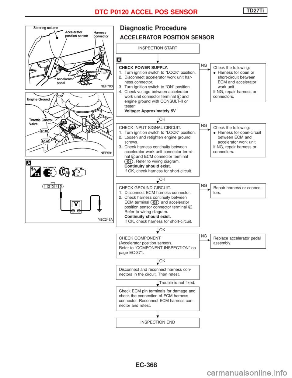
Diagnostic Procedure
ACCELERATOR POSITION SENSOR
INSPECTION START
CHECK POWER SUPPLY.
1. Turn ignition switch to ªLOCKº position.
2. Disconnect accelerator work unit har-
ness connector.
3. Turn ignition switch to ªONº position.
4. Check voltage between accelerator
work unit connector terminalq
5and
engine ground with CONSULT-II or
tester.
Voltage: Approximately 5V
OK
ENG
Check the following:
IHarness for open or
short-circuit between
ECM and accelerator
work unit.
If NG, repair harness or
connectors.
CHECK INPUT SIGNAL CIRCUIT.
1. Turn ignition switch to ªLOCKº position.
2. Loosen and retighten engine ground
screws.
3. Check harness continuity between
accelerator work unit connector termi-
nalq
2and ECM connector terminal
434. Refer to wiring diagram.
Continuity should exist.
If OK, check harness for short-circuit.
OK
ENG
Check the following:
IHarness for open-circuit
between ECM and
accelerator work unit
If NG, repair harness or
connectors.
CHECK GROUND CIRCUIT.
1. Disconnect ECM harness connector.
2. Check harness continuity between
ECM terminal
425and accelerator
position sensor connector terminalq
4.
Refer to wiring diagram.
Continuity should exist.
If OK, check harness for short-circuit.
OK
ENG
Repair harness or connec-
tors.
CHECK COMPONENT
(Accelerator position sensor).
Refer to ªCOMPONENT INSPECTIONº on
page EC-371.
OK
ENG
Replace accelerator pedal
assembly.
Disconnect and reconnect harness con-
nectors in the circuit. Then retest.
Trouble is not fixed.
Check ECM pin terminals for damage and
check the connection of ECM harness
connector. Reconnect ECM harness con-
nector and retest.
INSPECTION END
NEF700
NEF591
YEC246A
H
H
H
H
H
H
H
DTC P0120 ACCEL POS SENSORTD27Ti
EC-368
Page 732 of 1767

qA
CHECK INPUT SIGNAL CIRCUIT.
1. Turn ignition switch to ªLOCKº position.
2. Disconnect accelerator work unit har-
ness connector and ECM harness con-
nector.
3. Check harness continuity between
accelerator work unit terminalq
3and
ECM terminal
435. Refer to wiring
diagram.
Continuity should exist.
Check harness for short-circuit.
OK
ENG
Check the following:
I10A fuse in fuse box
I75A fusible link in fusible
link box
IHarness continuity
between ECM relay and
battery positive supply
IHarness for open or
short-circuit between
ECM relay and accelera-
tor position switch.
If NG, repair harness or
connectors.
CHECK GROUND CIRCUIT.
1. Turn ignition switch to ªLOCKº position.
2. Disconnect ECM harness connector.
3. Check harness continuity between
accelerator work unit connector termi-
nalq
1and ECM connector terminal
426. Refer to wiring diagram.
Continuity should exist.
If OK; check harness for short-circuit.
If OK, re-connect harness connectors.
OK
ENG
Repair harness or connec-
tors.
CHECK COMPONENT.
(Accelerator position switch.)
Refer to ªCOMPONENT INSPECTIONº on
page EC-371.
OK
ENG
Replace accelerator pedal.
Disconnect and reconnect harness con-
nectors in the circuits. Then retest.
Trouble is not fixed
Check ECM pin terminals for damage and
check the connection of ECM harness
connector. Reconnect ECM harness con-
nector and retest.
INSPECTION END
SEF628S
H
H
H
H
H
H
DTC P0120 ACCEL POS SENSORTD27Ti
Diagnostic Procedure (Cont'd)
EC-370
Page 735 of 1767
Wiring Diagram
YEC149A
DTC P0180 FUEL TEMP SENSORTD27Ti
EC-373
Page 739 of 1767
Wiring Diagram
YEC158A
DTC P0215 FUEL CUT S/V 1TD27Ti
EC-377
Page 740 of 1767

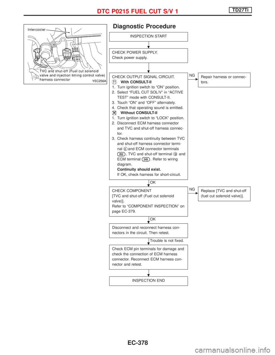
Diagnostic Procedure
INSPECTION START
CHECK POWER SUPPLY.
Check power supply.
CHECK OUTPUT SIGNAL CIRCUIT.
With CONSULT-II
1. Turn ignition switch to ªONº position.
2. Select ªFUEL CUT SOL/Vº in ªACTIVE
TESTº mode with CONSULT-II.
3. Touch ªONº and ªOFFº alternately.
4. Check that operating sound is emitted.
Without CONSULT-II
1. Turn ignition switch to ªLOCKº position.
2. Disconnect ECM harness connector
and TVC and shut-off harness connec-
tor.
3. Check harness continuity between TVC
and shut-off harness connector termi-
nalq
8and ECM connector terminals
202, TVC and shut-off terminalq10and
ECM terminal
349. Refer to wiring
diagram.
Continuity should exist.
If OK, check harness for short-circuit.
OK
ENG
Repair harness or connec-
tors.
CHECK COMPONENT
[TVC and shut-off (Fuel cut solenoid
valve)].
Refer to ªCOMPONENT INSPECTIONº on
page EC-379.
OK
ENG
Replace [TVC and shut-off
(fuel cut solenoid valve)].
Disconnect and reconnect harness con-
nectors in the circuit. Then retest.
Trouble is not fixed.
Check ECM pin terminals for damage and
check the connection of ECM harness
connector. Reconnect ECM harness con-
nector and retest.
INSPECTION END
YEC256A
H
H
H
H
H
H
DTC P0215 FUEL CUT S/V 1TD27Ti
EC-378
Page 744 of 1767
Wiring Diagram
YEC158A
DTC P0216 INJ TIMING CONT/V, DTC P1246 F/INJ TIMG F/BTD27Ti
EC-382