Page 800 of 1767

qB
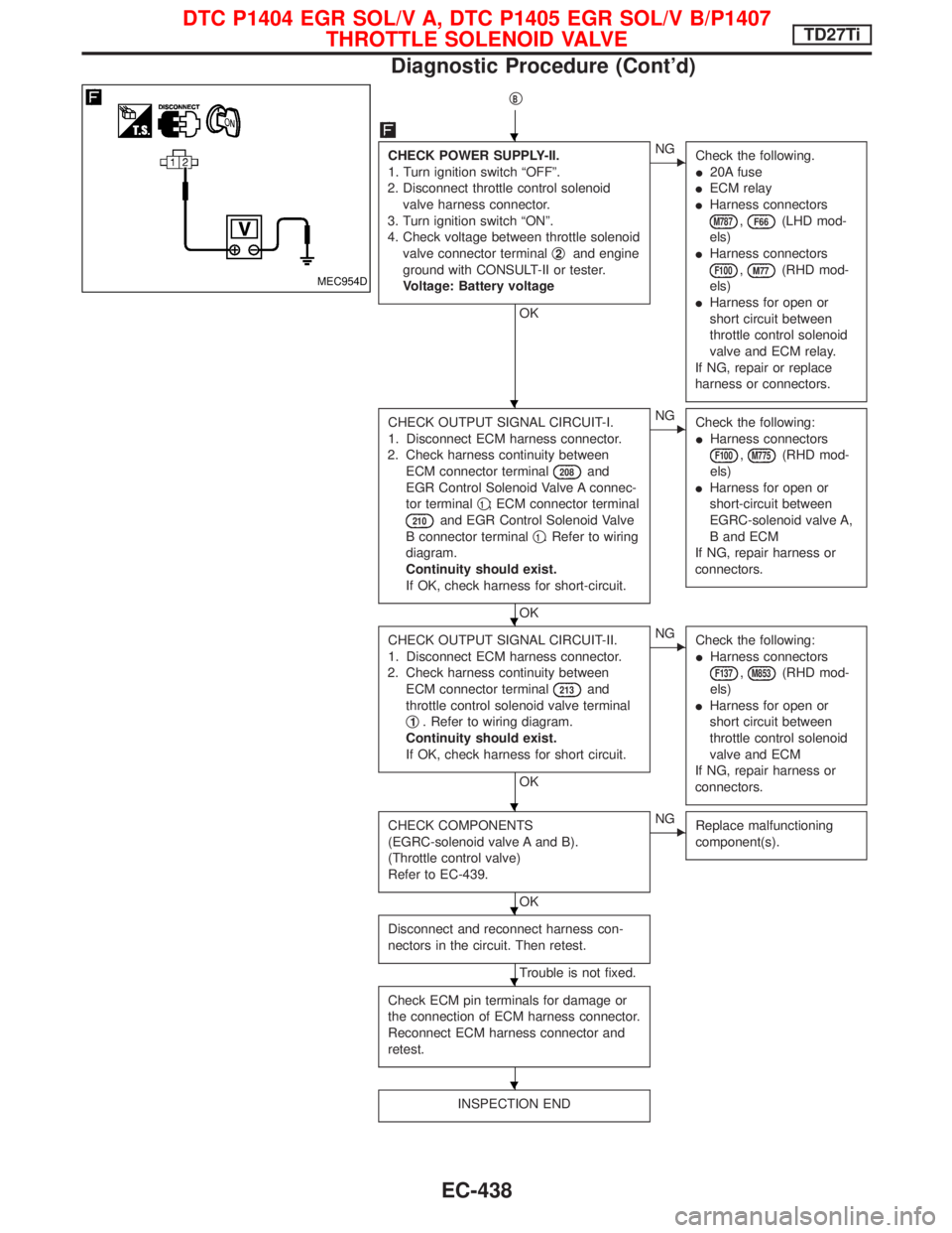
CHECK POWER SUPPLY-II.
1. Turn ignition switch ªOFFº.
2. Disconnect throttle control solenoid
valve harness connector.
3. Turn ignition switch ªONº.
4. Check voltage between throttle solenoid
valve connector terminalq
2and engine
ground with CONSULT-II or tester.
Voltage: Battery voltage
OK
ENG
Check the following.
I20A fuse
IECM relay
IHarness connectors
M787,F66(LHD mod-
els)
IHarness connectors
F100,M77(RHD mod-
els)
IHarness for open or
short circuit between
throttle control solenoid
valve and ECM relay.
If NG, repair or replace
harness or connectors.
CHECK OUTPUT SIGNAL CIRCUIT-I.
1. Disconnect ECM harness connector.
2. Check harness continuity between
ECM connector terminal
208and
EGR Control Solenoid Valve A connec-
tor terminalq
1; ECM connector terminal
210and EGR Control Solenoid Valve
B connector terminalq
1. Refer to wiring
diagram.
Continuity should exist.
If OK, check harness for short-circuit.
OK
ENG
Check the following:
IHarness connectors
F100,M775(RHD mod-
els)
IHarness for open or
short-circuit between
EGRC-solenoid valve A,
B and ECM
If NG, repair harness or
connectors.
CHECK OUTPUT SIGNAL CIRCUIT-II.
1. Disconnect ECM harness connector.
2. Check harness continuity between
ECM connector terminal
213and
throttle control solenoid valve terminal
q
1. Refer to wiring diagram.
Continuity should exist.
If OK, check harness for short circuit.
OK
ENG
Check the following:
IHarness connectors
F137,M853(RHD mod-
els)
IHarness for open or
short circuit between
throttle control solenoid
valve and ECM
If NG, repair harness or
connectors.
CHECK COMPONENTS
(EGRC-solenoid valve A and B).
(Throttle control valve)
Refer to EC-439.
OK
ENG
Replace malfunctioning
component(s).
Disconnect and reconnect harness con-
nectors in the circuit. Then retest.
Trouble is not fixed.
Check ECM pin terminals for damage or
the connection of ECM harness connector.
Reconnect ECM harness connector and
retest.
INSPECTION END
MEC954D
H
H
H
H
H
H
H
DTC P1404 EGR SOL/V A, DTC P1405 EGR SOL/V B/P1407
THROTTLE SOLENOID VALVETD27Ti
Diagnostic Procedure (Cont'd)
EC-438
Page 803 of 1767
Wiring Diagram
LHD MODELS
YEC154A
DTC P1530 AIR CONDITIONER RLYTD27Ti
EC-441
Page 804 of 1767
RHD MODELS
YEC155A
DTC P1530 AIR CONDITIONER RLYTD27Ti
Wiring Diagram (Cont'd)
EC-442
Page 805 of 1767

Diagnostic Procedure
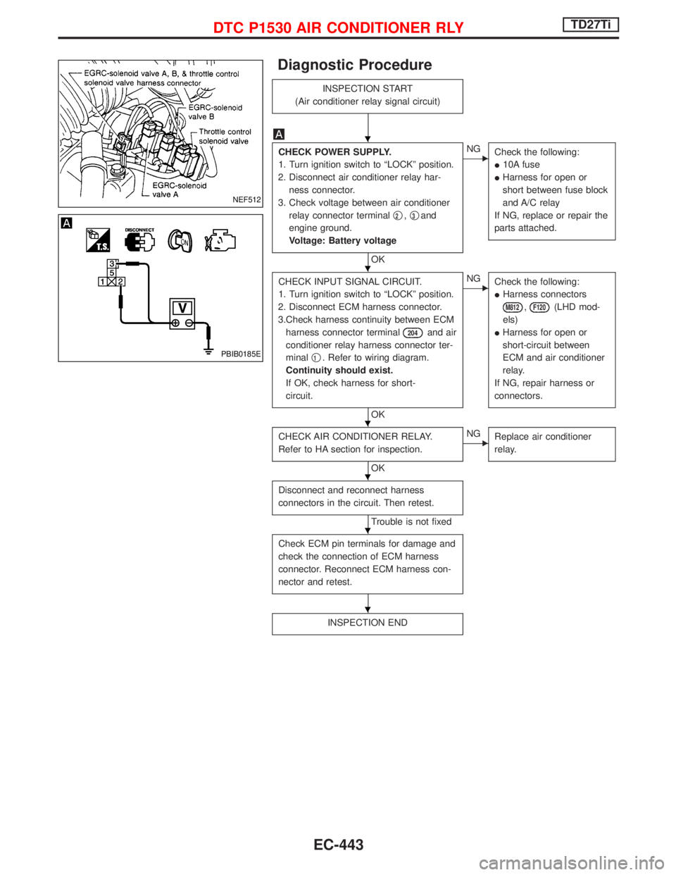
INSPECTION START
(Air conditioner relay signal circuit)
CHECK POWER SUPPLY.
1. Turn ignition switch to ªLOCKº position.
2. Disconnect air conditioner relay har-
ness connector.
3. Check voltage between air conditioner
relay connector terminalq
2,q3and
engine ground.
Voltage: Battery voltage
OK
ENG
Check the following:
I10A fuse
IHarness for open or
short between fuse block
and A/C relay
If NG, replace or repair the
parts attached.
CHECK INPUT SIGNAL CIRCUIT.
1. Turn ignition switch to ªLOCKº position.
2. Disconnect ECM harness connector.
3.Check harness continuity between ECM
harness connector terminal
204and air
conditioner relay harness connector ter-
minalq
1. Refer to wiring diagram.
Continuity should exist.
If OK, check harness for short-
circuit.
OK
ENG
Check the following:
IHarness connectors
M812,F120(LHD mod-
els)
IHarness for open or
short-circuit between
ECM and air conditioner
relay.
If NG, repair harness or
connectors.
CHECK AIR CONDITIONER RELAY.
Refer to HA section for inspection.
OK
ENG
Replace air conditioner
relay.
Disconnect and reconnect harness
connectors in the circuit. Then retest.
Trouble is not fixed
Check ECM pin terminals for damage and
check the connection of ECM harness
connector. Reconnect ECM harness con-
nector and retest.
INSPECTION END
NEF512
PBIB0185E
H
H
H
H
H
H
DTC P1530 AIR CONDITIONER RLYTD27Ti
EC-443
Page 809 of 1767
Wiring Diagram
YEC250A
DTC P1620 ECM RLYTD27Ti
EC-447
Page 810 of 1767

Diagnostic Procedure
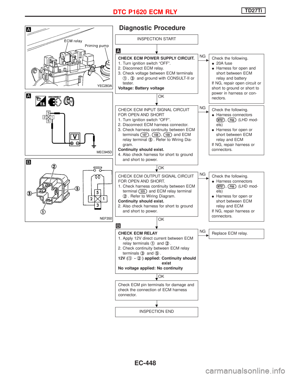
INSPECTION START
CHECK ECM POWER SUPPLY CIRCUIT.
1. Turn ignition switch ªOFFº.
2. Disconnect ECM relay.
3. Check voltage between ECM terminals
q
1,q3and ground with CONSULT-II or
tester.
Voltage: Battery voltage
OK
ENG
Check the following.
I20A fuse
IHarness for open and
short between ECM
relay and battery
If NG, repair open circuit or
short to ground or short to
power in harness or con-
nectors.
CHECK ECM INPUT SIGNAL CIRCUIT
FOR OPEN AND SHORT
1. Turn ignition switch ªOFFº.
2. Disconnect ECM harness connector.
3. Check harness continuity between ECM
terminals
107,108,109and ECM
relay terminalq
5. Refer to Wiring Dia-
gram.
Continuity should exist.
4. Also check harness for short to ground
and short to power.
OK
ENG
Check the following.
IHarness connectors
M787,F66(LHD mod-
els)
IHarness for open or
short between ECM
relay and ECM
If NG, repair harness or
connectors.
CHECK ECM OUTPUT SIGNAL CIRCUIT
FOR OPEN AND SHORT.
1. Check harness continuity between ECM
terminal
325and ECM relay terminal
q
2. Refer to Wiring Diagram.
Continuity should exist.
2. Also check harness for short to ground
and short to power.
OK
ENG
Check the following.
IHarness connectors
M787,F66(LHD mod-
els)
IHarness for open or
short between ECM
relay and ECM
If NG, repair harness or
connectors.
CHECK ECM RELAY
1. Apply 12V direct current between ECM
relay terminalsq
1andq2.
2. Check continuity between ECM relay
terminalsq
3andq5.
12V (q
1-q2) applied: Continuity should
exist
No voltage applied: No continuity
OK
ENG
Replace ECM relay.
Check ECM pin terminals for damage and
check the connection of ECM harness
connector.
INSPECTION END
YEC283A
MEC945D
NEF350
H
H
H
H
H
H
DTC P1620 ECM RLYTD27Ti
EC-448
Page 811 of 1767
Wiring Diagram
YEC153A
START SIGNALTD27Ti
EC-449
Page 812 of 1767

Diagnostic Procedure
INSPECTION START
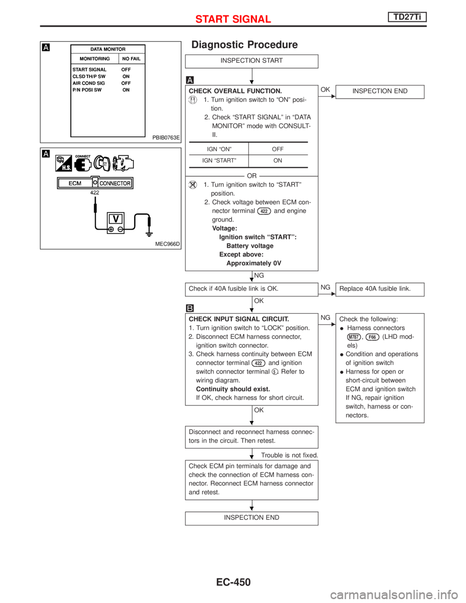
CHECK OVERALL FUNCTION.
1. Turn ignition switch to ªONº posi-
tion.
2. Check ªSTART SIGNALº in ªDATA
MONITORº mode with CONSULT-
II.
--------------------------------------------------------------------------------------------------------------------------------------OR--------------------------------------------------------------------------------------------------------------------------------------
1. Turn ignition switch to ªSTARTº
position.
2. Check voltage between ECM con-
nector terminal
422and engine
ground.
Voltage:
Ignition switch ªSTARTº:
Battery voltage
Except above:
Approximately 0V
NG
EOK
INSPECTION END
Check if 40A fusible link is OK.
OKENG
Replace 40A fusible link.
CHECK INPUT SIGNAL CIRCUIT.
1. Turn ignition switch to ªLOCKº position.
2. Disconnect ECM harness connector,
ignition switch connector.
3. Check harness continuity between ECM
connector terminal
422and ignition
switch connector terminalq
5. Refer to
wiring diagram.
Continuity should exist.
If OK, check harness for short circuit.
OK
ENG
Check the following:
IHarness connectors
M787,F66(LHD mod-
els)
ICondition and operations
of ignition switch
IHarness for open or
short-circuit between
ECM and ignition switch
If NG, repair ignition
switch, harness or con-
nectors.
Disconnect and reconnect harness connec-
tors in the circuit. Then retest.
Trouble is not fixed.
Check ECM pin terminals for damage and
check the connection of ECM harness con-
nector. Reconnect ECM harness connector
and retest.
INSPECTION END
IGN ªONº OFF
IGN ªSTARTº ON
PBIB0763E
MEC966D
H
H
H
H
H
H
START SIGNALTD27Ti
EC-450