Page 519 of 1767
Wiring Diagram
LHD MODELS
YEC187A
DTC 0504 A/T COMM LINEZD30DDTi
EC-157
Page 520 of 1767
RHD MODELS
YEC188A
DTC 0504 A/T COMM LINEZD30DDTi
Wiring Diagram (Cont'd)
EC-158
Page 521 of 1767
Diagnostic Procedure
1 CHECK INPUT SIGNAL CIRCUIT
1. Turn ignition switch ªOFFº.
2. Disconnect ECM harness connector and TCM (Transmission control module) harness connector.
MEC020E
MEC026E
3. Check harness continuity between the following terminals. Refer to Wiring Diagram.
MTBL0532
Continuity should exist.
OK or NG
OKEGO TO 3.
NGEGO TO 2.
2 DETECT MALFUNCTIONING PART
Check the following.
IHarness connectors M788, F93 (LHD models)
IHarness for open or short between ECM and TCM (Transmission control module)
ERepair harness or connectors.
DTC 0504 A/T COMM LINEZD30DDTi
EC-159
Page 522 of 1767
3 CHECK INPUT SIGNAL CIRCUIT
1. Check harness continuity between ECM terminal 24 and ground, ECM terminal 30 and ground, ECM terminal 37 and ground,
ECM terminal 58 and ground. Refer to Wiring Diagram.
Continuity should not exist.
2. Also check harness for short to ground and short to power.
OK or NG
OKEGO TO 5.
NGEGO TO 4.
4 DETECT MALFUNCTIONING PART
Check the harness for open or short between ECM and TCM (Transmission control module).
ERepair open circuit short to ground or short to power in harness.
5 CHECK INTERMITTENT INCIDENT
Refer to ªTROUBLE DIAGNOSIS FOR INTERMITTENT INCIDENTº, EC-78.
EINSPECTION END
DTC 0504 A/T COMM LINEZD30DDTi
Diagnostic Procedure (Cont'd)
EC-160
Page 526 of 1767
Wiring Diagram
LHD MODELS
YEC181A
DTC 0701 P1×CAM POS SENZD30DDTi
EC-164
Page 527 of 1767
RHD MODELS
YEC182A
DTC 0701 P1×CAM POS SENZD30DDTi
Wiring Diagram (Cont'd)
EC-165
Page 528 of 1767

Diagnostic Procedure
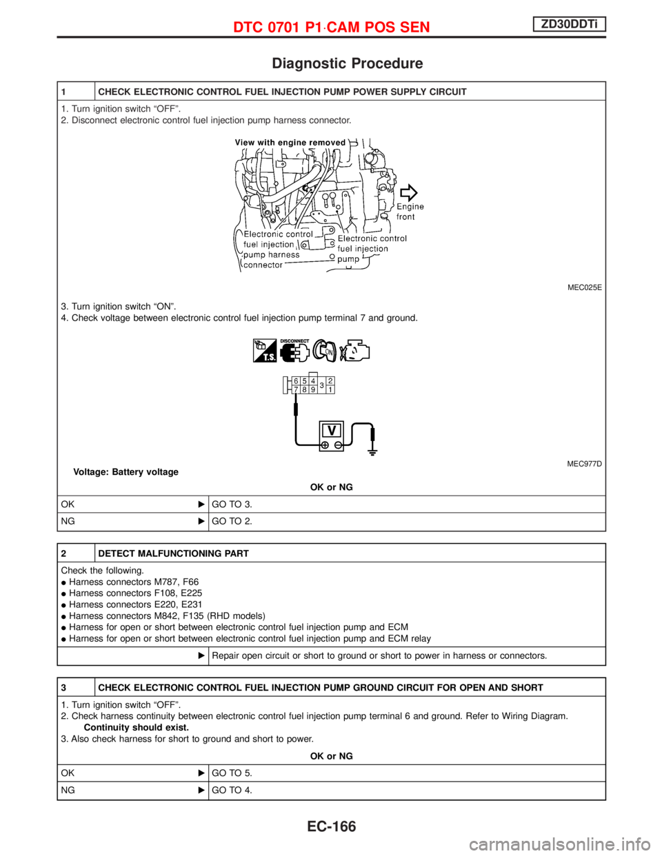
1 CHECK ELECTRONIC CONTROL FUEL INJECTION PUMP POWER SUPPLY CIRCUIT
1. Turn ignition switch ªOFFº.
2. Disconnect electronic control fuel injection pump harness connector.
MEC025E
3. Turn ignition switch ªONº.
4. Check voltage between electronic control fuel injection pump terminal 7 and ground.
MEC977DVoltage: Battery voltage
OK or NG
OKEGO TO 3.
NGEGO TO 2.
2 DETECT MALFUNCTIONING PART
Check the following.
IHarness connectors M787, F66
IHarness connectors F108, E225
IHarness connectors E220, E231
IHarness connectors M842, F135 (RHD models)
IHarness for open or short between electronic control fuel injection pump and ECM
IHarness for open or short between electronic control fuel injection pump and ECM relay
ERepair open circuit or short to ground or short to power in harness or connectors.
3 CHECK ELECTRONIC CONTROL FUEL INJECTION PUMP GROUND CIRCUIT FOR OPEN AND SHORT
1. Turn ignition switch ªOFFº.
2. Check harness continuity between electronic control fuel injection pump terminal 6 and ground. Refer to Wiring Diagram.
Continuity should exist.
3. Also check harness for short to ground and short to power.
OK or NG
OKEGO TO 5.
NGEGO TO 4.
DTC 0701 P1×CAM POS SENZD30DDTi
EC-166
Page 529 of 1767

4 DETECT MALFUNCTIONING PART
Check the following.
IHarness connectors E231, E220
IHarness for open or short between electronic control fuel injection pump and engine ground
ERepair open circuit or short to ground or short to power in harness or connectors.
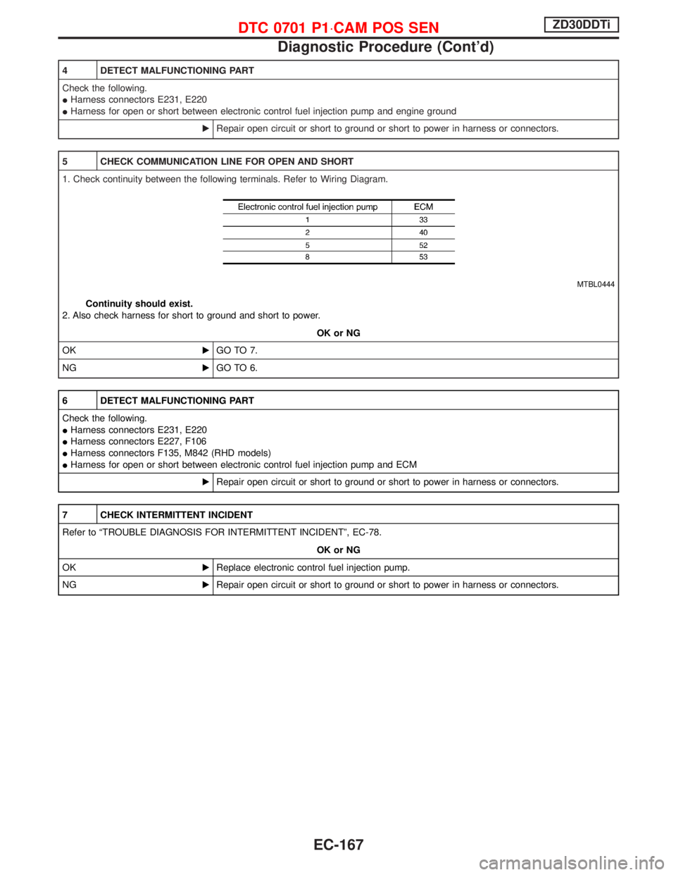
5 CHECK COMMUNICATION LINE FOR OPEN AND SHORT
1. Check continuity between the following terminals. Refer to Wiring Diagram.
MTBL0444
Continuity should exist.
2. Also check harness for short to ground and short to power.
OK or NG
OKEGO TO 7.
NGEGO TO 6.
6 DETECT MALFUNCTIONING PART
Check the following.
IHarness connectors E231, E220
IHarness connectors E227, F106
IHarness connectors F135, M842 (RHD models)
IHarness for open or short between electronic control fuel injection pump and ECM
ERepair open circuit or short to ground or short to power in harness or connectors.
7 CHECK INTERMITTENT INCIDENT
Refer to ªTROUBLE DIAGNOSIS FOR INTERMITTENT INCIDENTº, EC-78.
OK or NG
OKEReplace electronic control fuel injection pump.
NGERepair open circuit or short to ground or short to power in harness or connectors.
DTC 0701 P1×CAM POS SENZD30DDTi
Diagnostic Procedure (Cont'd)
EC-167