Page 380 of 1767
Vacuum Hose Drawing
1. Swirl control valve control solenoid
valve to swirl control valve actua-
tor
2. Intake air control valve control
solenoid valve to intake air control
valve actuator3. Variable nozzle turbocharger con-
trol actuator to vacuum damper
4. Variable nozzle turbocharger con-
trol solenoid valve to resonator5. Variable nozzle turbocharger con-
trol solenoid valve to vacuum
pump
Refer to ªSystem Diagramº, EC-17 for vacuum control system.
MEC030E
ENGINE AND EMISSION CONTROL OVERALL SYSTEMZD30DDTi
EC-18
Page 442 of 1767
WIRING DIAGRAM
YEC171A
TROUBLE DIAGNOSIS FOR POWER SUPPLYZD30DDTi
Main Power Supply and Ground Circuit
(Cont'd)
EC-80
Page 444 of 1767
DIAGNOSTIC PROCEDURE
1 INSPECTION START
Start engine.
Is engine running?
YesorNo
Ye sEGO TO 14.
NoEGO TO 2.
2 CHECK ECM POWER SUPPLY CIRCUIT-I
1. Turn ignition switch ªONº.
2. Check voltage between ECM terminal 38 and ground with CONSULT-II or tester.
SEF397Y
OK or NG
OKEGO TO 4.
NGEGO TO 3.
3 DETECT MALFUNCTIONING PART
Check the following.
I10A fuse
IHarness for open or short between ECM and fuse
ERepair open circuit or short to ground or short to power in harness or connectors.
4 CHECK ECM GROUND CIRCUIT FOR OPEN AND SHORT
1. Turn ignition switch ªOFFº.
2. Disconnect ECM harness connector.
3. Check harness continuity between ECM terminals 39, 43, 106, 112, 118 and engine ground. Refer to Wiring Diagram.
Continuity should exist.
4. Also check harness for short to ground and short to power.
OK or NG
OKEGO TO 6.
NGEGO TO 5.
TROUBLE DIAGNOSIS FOR POWER SUPPLYZD30DDTi
Main Power Supply and Ground Circuit
(Cont'd)
EC-82
Page 446 of 1767
7 CHECK ECM POWER SUPPLY CIRCUIT-III
1. Disconnect ECM relay.
MEC021E
2. Check voltage between relay terminals 2, 3 and ground with CONSULT-II or tester.
MEC978DVoltage: Battery Voltage
OK or NG
OKEGO TO 9.
NGEGO TO 8.
8 DETECT MALFUNCTIONING PART
Check the following.
I10A fuse
I15A fuse
IHarness for open or short between ECM relay and battery
ERepair open circuit or short to ground or short to power in harness or connectors.
9 CHECK OUTPUT SIGNAL CIRCUIT FOR OPEN AND SHORT
1. Disconnect ECM harness connector.
2. Check harness continuity between ECM terminal 4 and ECM relay terminal 1. Refer to Wiring Diagram.
Continuity should exist.
3. Also check harness for short to ground and short to power.
OK or NG
OKEGO TO 11.
NGEGO TO 10.
TROUBLE DIAGNOSIS FOR POWER SUPPLYZD30DDTi
Main Power Supply and Ground Circuit
(Cont'd)
EC-84
Page 447 of 1767

10 DETECT MALFUNCTIONING PART
Check the following.
IHarness connectors M787, F66 (LHD models)
IHarness for open or short between ECM and ECM relay
ERepair open circuit or short to ground or short to power in harness or connectors.
11 CHECK ECM POWER SUPPLY CIRCUIT-IV
1. Check harness continuity between ECM terminals 56, 61, 116 and ECM relay terminal 5. Refer to Wiring Diagram.
Continuity should exist.
2. Also check harness for short to ground and short to power.
OK or NG
OKEGO TO 13.
NGEGO TO 12.
12 DETECT MALFUNCTIONING PART
Check the following.
IHarness connectors M787, F66 (LHD models)
IHarness for open or short between ECM and ECM relay
ERepair open circuit or short to ground or short to power in harness or connectors.
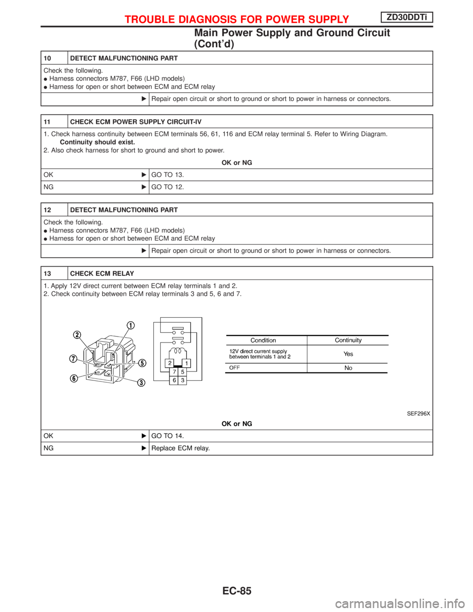
13 CHECK ECM RELAY
1. Apply 12V direct current between ECM relay terminals 1 and 2.
2. Check continuity between ECM relay terminals 3 and 5, 6 and 7.
SEF296X
OK or NG
OKEGO TO 14.
NGEReplace ECM relay.
TROUBLE DIAGNOSIS FOR POWER SUPPLYZD30DDTi
Main Power Supply and Ground Circuit
(Cont'd)
EC-85
Page 448 of 1767
14 CHECK ECM POWER SUPPLY CIRCUIT-V
1. Reconnect all harness connectors disconnected.
2. Turn ignition switch ªONº.
3. Check voltage between ECM terminal 102 and ground with CONSULT-II or tester.
SEF290Z
OK or NG
OKEGO TO 16.
NGEGO TO 15.
15 DETECT MALFUNCTIONING PART
Check the following.
I10A fuse
IHarness for open or short between ECM and fuse
ERepair open circuit or short to ground or short to power in harness or connectors.
16 CHECK ECM POWER SUPPLY CIRCUIT-VI
1. Turn ignition switch ªOFFº.
2. Disconnect ECM relay.
MEC021E
3. Disconnect ECM harness connector.
4. Check harness continuity between ECM terminals 56, 61, 116 and ECM relay terminal 5. Refer to Wiring Diagram.
Continuity should exist.
5. Also check harness for short to ground and short to power.
OK or NG
OKEGO TO 18.
NGEGO TO 17.
TROUBLE DIAGNOSIS FOR POWER SUPPLYZD30DDTi
Main Power Supply and Ground Circuit
(Cont'd)
EC-86
Page 449 of 1767

17 DETECT MALFUNCTIONING PART
Check the following.
IHarness connectors M787, F66 (LHD models)
IHarness for open or short between ECM and ECM relay
ERepair open circuit or short to ground or short to power in harness or connectors.
18 CHECK ECM GROUND CIRCUIT FOR OPEN AND SHORT
1. Check harness continuity between ECM terminals 39, 43, 106, 112, 118 and engine ground. Refer to Wiring Diagram.
Continuity should exist.
2. Also check harness for short to ground and short to power.
OK or NG
OKEGO TO 20.
NGEGO TO 19.
19 DETECT MALFUNCTIONING PART
Check the following.
IHarness connectors F108, E225
IHarness connectors M842, F135 (RHD models)
IHarness for open or short between ECM and engine ground
ERepair open circuit or short to ground or short to power in harness or connectors.
20 CHECK INTERMITTENT INCIDENT
Refer to ªTROUBLE DIAGNOSIS FOR INTERMITTENT INCIDENTº, EC-78.
EINSPECTION END
TROUBLE DIAGNOSIS FOR POWER SUPPLYZD30DDTi
Main Power Supply and Ground Circuit
(Cont'd)
EC-87
Page 452 of 1767
Wiring Diagram
LHD MODELS
YEC173A
DTC 0102 MASS AIR FLOW SENZD30DDTi
EC-90