Page 84 of 1767
Wiring Diagram Ð AT Ð LPSV
LHD MODELS
YAT278
TROUBLE DIAGNOSIS FOR LINE PRESSURE S/V
AT-82
Page 85 of 1767
RHD MODELS
YAT279
TROUBLE DIAGNOSIS FOR LINE PRESSURE S/V
Wiring Diagram Ð AT Ð LPSV (Cont'd)
AT-83
Page 89 of 1767
Wiring Diagram Ð AT Ð PNP/SW
YAT269
TROUBLE DIAGNOSIS FOR NON-DETECTABLE ITEMS
AT-87
Page 203 of 1767

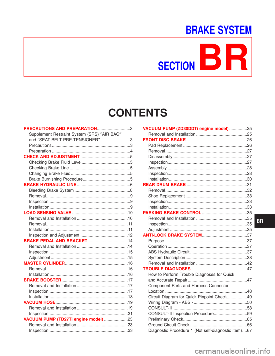
BRAKE SYSTEM
SECTION
BR
CONTENTS
PRECAUTIONS AND PREPARATION............................3
Supplement Restraint System (SRS)²AIR BAG²
and²SEAT BELT PRE-TENSIONER².........................3
Precautions ..................................................................3
Preparation ..................................................................4
CHECK AND ADJUSTMENT..........................................5
Checking Brake Fluid Level.........................................5
Checking Brake Line ...................................................5
Changing Brake Fluid ..................................................5
Brake Burnishing Procedure........................................5
BRAKE HYDRAULIC LINE.............................................6
Bleeding Brake System ...............................................8
Removal .......................................................................9
Inspection.....................................................................9
Installation ....................................................................9
LOAD SENSING VALVE...............................................10
Removal and Installation ...........................................10
Removal ..................................................................... 11
Installation .................................................................. 11
Inspection and Adjustment ........................................12
BRAKE PEDAL AND BRACKET..................................14
Removal and Installation ...........................................14
Inspection...................................................................15
Adjustment .................................................................15
MASTER CYLINDER.....................................................16
Removal .....................................................................16
Installation ..................................................................16
BRAKE BOOSTER........................................................17
Removal and Installation ...........................................17
Inspection...................................................................17
Installation ..................................................................18
VACUUM HOSE.............................................................19
Removal and Installation ...........................................19
Inspection...................................................................21
VACUUM PUMP (TD27Ti engine model)....................23
Removal and Installation ...........................................23
Inspection...................................................................23VACUUM PUMP (ZD30DDTi engine model)...............25
Removal and Installation ...........................................25
FRONT DISC BRAKE...................................................26
Pad Replacement ......................................................26
Removal .....................................................................27
Disassembly...............................................................27
Inspection...................................................................27
Assembly ...................................................................28
Inspection...................................................................28
Installation ..................................................................30
REAR DRUM BRAKE...................................................31
Removal .....................................................................32
Shoe Replacement ....................................................33
Inspection...................................................................33
Installation ..................................................................33
PARKING BRAKE CONTROL......................................35
Removal and Installation ...........................................35
Inspection...................................................................35
Adjustment .................................................................35
ANTI-LOCK BRAKE SYSTEM......................................37
Purpose......................................................................37
Operation ...................................................................37
ABS Hydraulic Circuit ................................................37
System Description ....................................................38
Removal and Installation ...........................................42
TROUBLE DIAGNOSES...............................................47
How to Perform Trouble Diagnoses for Quick
and Accurate Repair ..................................................47
Component Parts and Harness Connector
Location .....................................................................48
Circuit Diagram for Quick Pinpoint Check.................49
Wiring Diagram - ABS - .............................................50
CONSULT-II ...............................................................58
CONSULT-II Inspection Procedure............................59
Preliminary Check......................................................65
Ground Circuit Check ................................................66
Diagnostic Procedure 1 (Not self-diagnostic item) ....67
Page 251 of 1767
Circuit Diagram for Quick Pinpoint Check
YBR244
TROUBLE DIAGNOSES
BR-49
Page 252 of 1767
Wiring Diagram Ð ABS Ð
LHD MODELS
YBR245
TROUBLE DIAGNOSES
BR-50
Page 253 of 1767
YBR246
TROUBLE DIAGNOSES
Wiring Diagram Ð ABS Ð (Cont'd)
BR-51
Page 254 of 1767
YBR247
TROUBLE DIAGNOSES
Wiring Diagram Ð ABS Ð (Cont'd)
BR-52