Page 453 of 1767
RHD MODELS
YEC174A
DTC 0102 MASS AIR FLOW SENZD30DDTi
Wiring Diagram (Cont'd)
EC-91
Page 455 of 1767

3 CHECK MAFS GROUND CIRCUIT FOR OPEN AND SHORT
1. Turn ignition switch ªOFFº.
2. Loosen and retighten engine ground screws.
MEC994D
3. Check harness continuity between mass air flow sensor terminal 3 and engine ground. Refer to Wiring Diagram.
Continuity should exist.
4. Also check harness for short to ground and short to power.
OK or NG
OKEGO TO 5.
NGEGO TO 4.
4 DETECT MALFUNCTIONING PART
Check the following.
IHarness connectors F135, M842 (RHD models)
IHarness for open or short between mass air flow sensor and ECM
ERepair open circuit or short to ground or short to power in harness or connectors.
5 CHECK MAFS INPUT SIGNAL CIRCUIT FOR OPEN AND SHORT
1. Disconnect ECM harness connector.
2. Check harness continuity between mass air flow sensor terminal 5 and ECM terminal 35. Refer to Wiring Diagram.
Continuity should exist.
3. Also check harness for short to ground and short to power.
OK or NG
OKEGO TO 7.
NGEGO TO 6.
6 DETECT MALFUNCTIONING PART
Check the following.
IHarness connectors F135, M842 (RHD models)
IHarness for open or short between mass air flow sensor and ECM
ERepair open circuit or short to ground or short to power in harness or connectors.
DTC 0102 MASS AIR FLOW SENZD30DDTi
Diagnostic Procedure (Cont'd)
EC-93
Page 458 of 1767
Wiring Diagram
YEC175A
DTC 0103 COOLANT TEMP SENZD30DDTi
EC-96
Page 459 of 1767
Diagnostic Procedure
1 CHECK ECTS POWER SUPPLY CIRCUIT
1. Turn ignition switch ªOFFº.
2. Disconnect engine coolant temperature sensor harness connector.
MEC022E
3. Turn ignition switch ªONº.
4. Check voltage between ECTS terminal 2 and ground with CONSULT-II or tester.
SEF401Y
OK or NG
OKEGO TO 3.
NGEGO TO 2.
2 DETECT MALFUNCTIONING PART
Check the following.
IHarness connectors E225, F108
IHarness connectors F135, M842 (RHD models)
IHarness for open or short between engine control temperature sensor and ECM
ERepair open circuit or short to ground or short to power in harness or connectors.
3 CHECK ECTS GROUND CIRCUIT FOR OPEN AND SHORT
1. Turn ignition switch ªOFFº.
2. Check harness continuity between ECTS terminal 1 and engine ground. Refer to Wiring Diagram.
Continuity should exist.
3. Also check harness for short to ground and short to power.
OK or NG
OKEGO TO 5.
NGEGO TO 4.
DTC 0103 COOLANT TEMP SENZD30DDTi
EC-97
Page 463 of 1767
Wiring Diagram
LHD MODELS
YEC176A
DTC 0104 VEHICLE SPEED SENZD30DDTi
EC-101
Page 464 of 1767
RHD MODELS
YEC177A
DTC 0104 VEHICLE SPEED SENZD30DDTi
Wiring Diagram (Cont'd)
EC-102
Page 465 of 1767

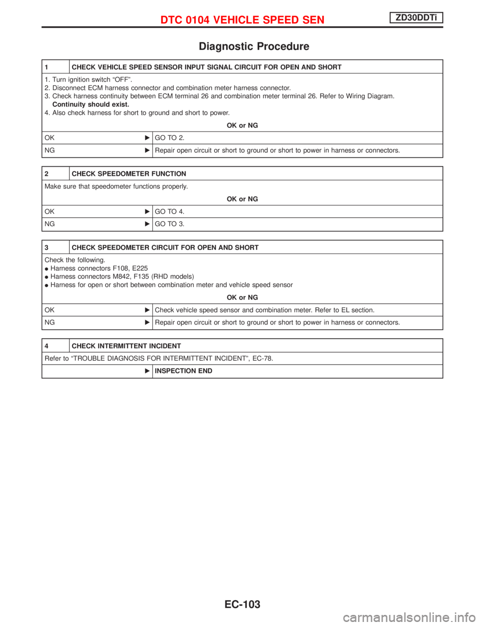
Diagnostic Procedure
1 CHECK VEHICLE SPEED SENSOR INPUT SIGNAL CIRCUIT FOR OPEN AND SHORT
1. Turn ignition switch ªOFFº.
2. Disconnect ECM harness connector and combination meter harness connector.
3. Check harness continuity between ECM terminal 26 and combination meter terminal 26. Refer to Wiring Diagram.
Continuity should exist.
4. Also check harness for short to ground and short to power.
OK or NG
OKEGO TO 2.
NGERepair open circuit or short to ground or short to power in harness or connectors.
2 CHECK SPEEDOMETER FUNCTION
Make sure that speedometer functions properly.
OK or NG
OKEGO TO 4.
NGEGO TO 3.
3 CHECK SPEEDOMETER CIRCUIT FOR OPEN AND SHORT
Check the following.
IHarness connectors F108, E225
IHarness connectors M842, F135 (RHD models)
IHarness for open or short between combination meter and vehicle speed sensor
OK or NG
OKECheck vehicle speed sensor and combination meter. Refer to EL section.
NGERepair open circuit or short to ground or short to power in harness or connectors.
4 CHECK INTERMITTENT INCIDENT
Refer to ªTROUBLE DIAGNOSIS FOR INTERMITTENT INCIDENTº, EC-78.
EINSPECTION END
DTC 0104 VEHICLE SPEED SENZD30DDTi
EC-103
Page 468 of 1767
Wiring Diagram
YEC178A
DTC 0203 ACCEL POS SW (F/C)ZD30DDTi
EC-106