2002 DODGE RAM warning
[x] Cancel search: warningPage 1317 of 2255
(5) Push therightfuel rail down until fuel injec-
tors have bottomed on injector shoulder. Push the
leftfuel rail down until fuel injectors have bottomed
on injector shoulder.
(6) Install fuel rail mounting bolts.
(7) Connect electrical connector to intake manifold
air temperature sensor.
(8) Connect electrical connectors at all fuel injec-
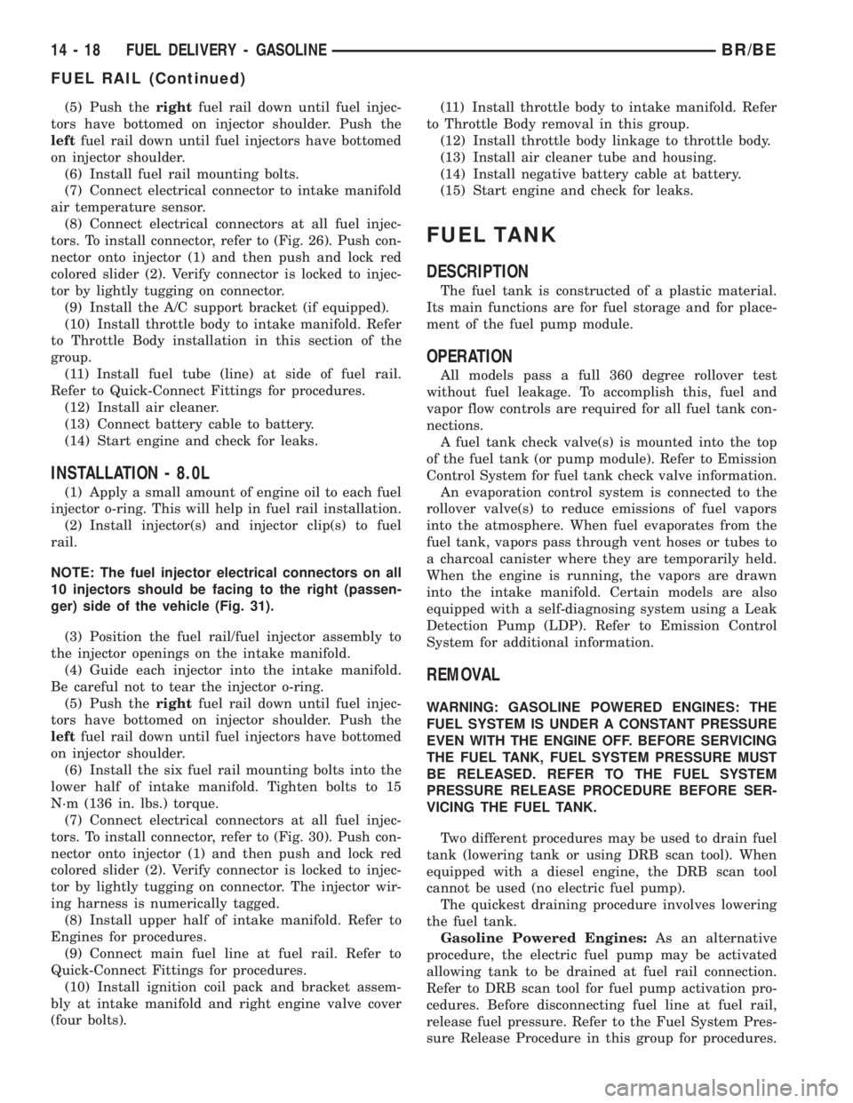
tors. To install connector, refer to (Fig. 26). Push con-
nector onto injector (1) and then push and lock red
colored slider (2). Verify connector is locked to injec-
tor by lightly tugging on connector.
(9) Install the A/C support bracket (if equipped).
(10) Install throttle body to intake manifold. Refer
to Throttle Body installation in this section of the
group.
(11) Install fuel tube (line) at side of fuel rail.
Refer to Quick-Connect Fittings for procedures.
(12) Install air cleaner.
(13) Connect battery cable to battery.
(14) Start engine and check for leaks.
INSTALLATION - 8.0L
(1) Apply a small amount of engine oil to each fuel
injector o-ring. This will help in fuel rail installation.
(2) Install injector(s) and injector clip(s) to fuel
rail.
NOTE: The fuel injector electrical connectors on all
10 injectors should be facing to the right (passen-
ger) side of the vehicle (Fig. 31).
(3) Position the fuel rail/fuel injector assembly to
the injector openings on the intake manifold.
(4) Guide each injector into the intake manifold.
Be careful not to tear the injector o-ring.
(5) Push therightfuel rail down until fuel injec-
tors have bottomed on injector shoulder. Push the
leftfuel rail down until fuel injectors have bottomed
on injector shoulder.
(6) Install the six fuel rail mounting bolts into the
lower half of intake manifold. Tighten bolts to 15
N´m (136 in. lbs.) torque.
(7) Connect electrical connectors at all fuel injec-
tors. To install connector, refer to (Fig. 30). Push con-
nector onto injector (1) and then push and lock red
colored slider (2). Verify connector is locked to injec-
tor by lightly tugging on connector. The injector wir-
ing harness is numerically tagged.
(8) Install upper half of intake manifold. Refer to
Engines for procedures.
(9) Connect main fuel line at fuel rail. Refer to
Quick-Connect Fittings for procedures.
(10) Install ignition coil pack and bracket assem-
bly at intake manifold and right engine valve cover
(four bolts).(11) Install throttle body to intake manifold. Refer
to Throttle Body removal in this group.
(12) Install throttle body linkage to throttle body.
(13) Install air cleaner tube and housing.
(14) Install negative battery cable at battery.
(15) Start engine and check for leaks.
FUEL TANK
DESCRIPTION
The fuel tank is constructed of a plastic material.
Its main functions are for fuel storage and for place-
ment of the fuel pump module.
OPERATION
All models pass a full 360 degree rollover test
without fuel leakage. To accomplish this, fuel and
vapor flow controls are required for all fuel tank con-
nections.
A fuel tank check valve(s) is mounted into the top
of the fuel tank (or pump module). Refer to Emission
Control System for fuel tank check valve information.
An evaporation control system is connected to the
rollover valve(s) to reduce emissions of fuel vapors
into the atmosphere. When fuel evaporates from the
fuel tank, vapors pass through vent hoses or tubes to
a charcoal canister where they are temporarily held.
When the engine is running, the vapors are drawn
into the intake manifold. Certain models are also
equipped with a self-diagnosing system using a Leak
Detection Pump (LDP). Refer to Emission Control
System for additional information.
REMOVAL
WARNING: GASOLINE POWERED ENGINES: THE
FUEL SYSTEM IS UNDER A CONSTANT PRESSURE
EVEN WITH THE ENGINE OFF. BEFORE SERVICING
THE FUEL TANK, FUEL SYSTEM PRESSURE MUST
BE RELEASED. REFER TO THE FUEL SYSTEM
PRESSURE RELEASE PROCEDURE BEFORE SER-
VICING THE FUEL TANK.
Two different procedures may be used to drain fuel
tank (lowering tank or using DRB scan tool). When
equipped with a diesel engine, the DRB scan tool
cannot be used (no electric fuel pump).
The quickest draining procedure involves lowering
the fuel tank.
Gasoline Powered Engines:As an alternative
procedure, the electric fuel pump may be activated
allowing tank to be drained at fuel rail connection.
Refer to DRB scan tool for fuel pump activation pro-
cedures. Before disconnecting fuel line at fuel rail,
release fuel pressure. Refer to the Fuel System Pres-
sure Release Procedure in this group for procedures.
14 - 18 FUEL DELIVERY - GASOLINEBR/BE
FUEL RAIL (Continued)
Page 1318 of 2255
Attach end of special test hose tool number 6541,
6539, 6631 or 6923 at fuel rail disconnection (tool
number will depend on model and/or engine applica-
tion). Position opposite end of this hose tool to an
approved gasoline draining station. Activate fuel
pump and drain tank until empty.
If electric fuel pump is not operating, tank must be
lowered for fuel draining. Refer to following proce-
dures.
(1) Remove fuel tank filler tube cap.
(2) Perform Fuel System Pressure Release proce-
dure as described in this group.
(3) Gasoline Engines: Disconnect negative battery
cable at battery. Diesel Engines: Disconnect both neg-
ative battery cables at both batteries.
(4) Raise vehicle on hoist.
(5) Certain models are equipped with a separate
grounding wire (strap) connecting the fuel fill tube
assembly to the body. Disconnect wire by removing
screw.
(6) Open fuel fill door and remove screws mount-
ing fuel filler tube assembly to body. Do not discon-
nect rubber fuel fill or vent hoses from tank at this
time.
(7) Place a transmission jack under center of fuel
tank. Apply a slight amount of pressure to fuel tank
with transmission jack.
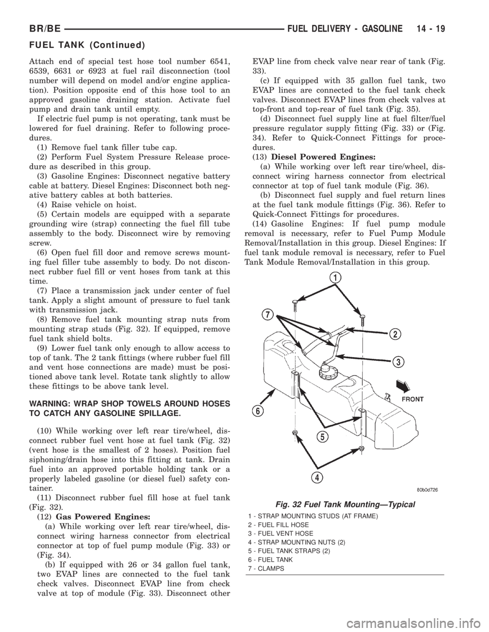
(8) Remove fuel tank mounting strap nuts from
mounting strap studs (Fig. 32). If equipped, remove
fuel tank shield bolts.
(9) Lower fuel tank only enough to allow access to
top of tank. The 2 tank fittings (where rubber fuel fill
and vent hose connections are made) must be posi-
tioned above tank level. Rotate tank slightly to allow
these fittings to be above tank level.
WARNING: WRAP SHOP TOWELS AROUND HOSES
TO CATCH ANY GASOLINE SPILLAGE.
(10) While working over left rear tire/wheel, dis-
connect rubber fuel vent hose at fuel tank (Fig. 32)
(vent hose is the smallest of 2 hoses). Position fuel
siphoning/drain hose into this fitting at tank. Drain
fuel into an approved portable holding tank or a
properly labeled gasoline (or diesel fuel) safety con-
tainer.
(11) Disconnect rubber fuel fill hose at fuel tank
(Fig. 32).
(12)Gas Powered Engines:
(a) While working over left rear tire/wheel, dis-
connect wiring harness connector from electrical
connector at top of fuel pump module (Fig. 33) or
(Fig. 34).
(b) If equipped with 26 or 34 gallon fuel tank,
two EVAP lines are connected to the fuel tank
check valves. Disconnect EVAP line from check
valve at top of module (Fig. 33). Disconnect otherEVAP line from check valve near rear of tank (Fig.
33).
(c) If equipped with 35 gallon fuel tank, two
EVAP lines are connected to the fuel tank check
valves. Disconnect EVAP lines from check valves at
top-front and top-rear of fuel tank (Fig. 35).
(d) Disconnect fuel supply line at fuel filter/fuel
pressure regulator supply fitting (Fig. 33) or (Fig.
34). Refer to Quick-Connect Fittings for proce-
dures.
(13)Diesel Powered Engines:
(a) While working over left rear tire/wheel, dis-
connect wiring harness connector from electrical
connector at top of fuel tank module (Fig. 36).
(b) Disconnect fuel supply and fuel return lines
at the fuel tank module fittings (Fig. 36). Refer to
Quick-Connect Fittings for procedures.
(14) Gasoline Engines: If fuel pump module
removal is necessary, refer to Fuel Pump Module
Removal/Installation in this group. Diesel Engines: If
fuel tank module removal is necessary, refer to Fuel
Tank Module Removal/Installation in this group.
Fig. 32 Fuel Tank MountingÐTypical
1 - STRAP MOUNTING STUDS (AT FRAME)
2 - FUEL FILL HOSE
3 - FUEL VENT HOSE
4 - STRAP MOUNTING NUTS (2)
5 - FUEL TANK STRAPS (2)
6 - FUEL TANK
7 - CLAMPS
BR/BEFUEL DELIVERY - GASOLINE 14 - 19
FUEL TANK (Continued)
Page 1321 of 2255
REMOVAL
WARNING: THE FUEL SYSTEM IS UNDER A CON-
STANT PRESSURE (EVEN WITH THE ENGINE OFF).
BEFORE SERVICING THE CHECK VALVE, FUEL
SYSTEM PRESSURE MUST BE RELEASED (GASO-
LINE POWERED ENGINES ONLY). REFER TO THE
FUEL PRESSURE RELEASE PROCEDURE IN
GROUP 14, FUEL SYSTEM.
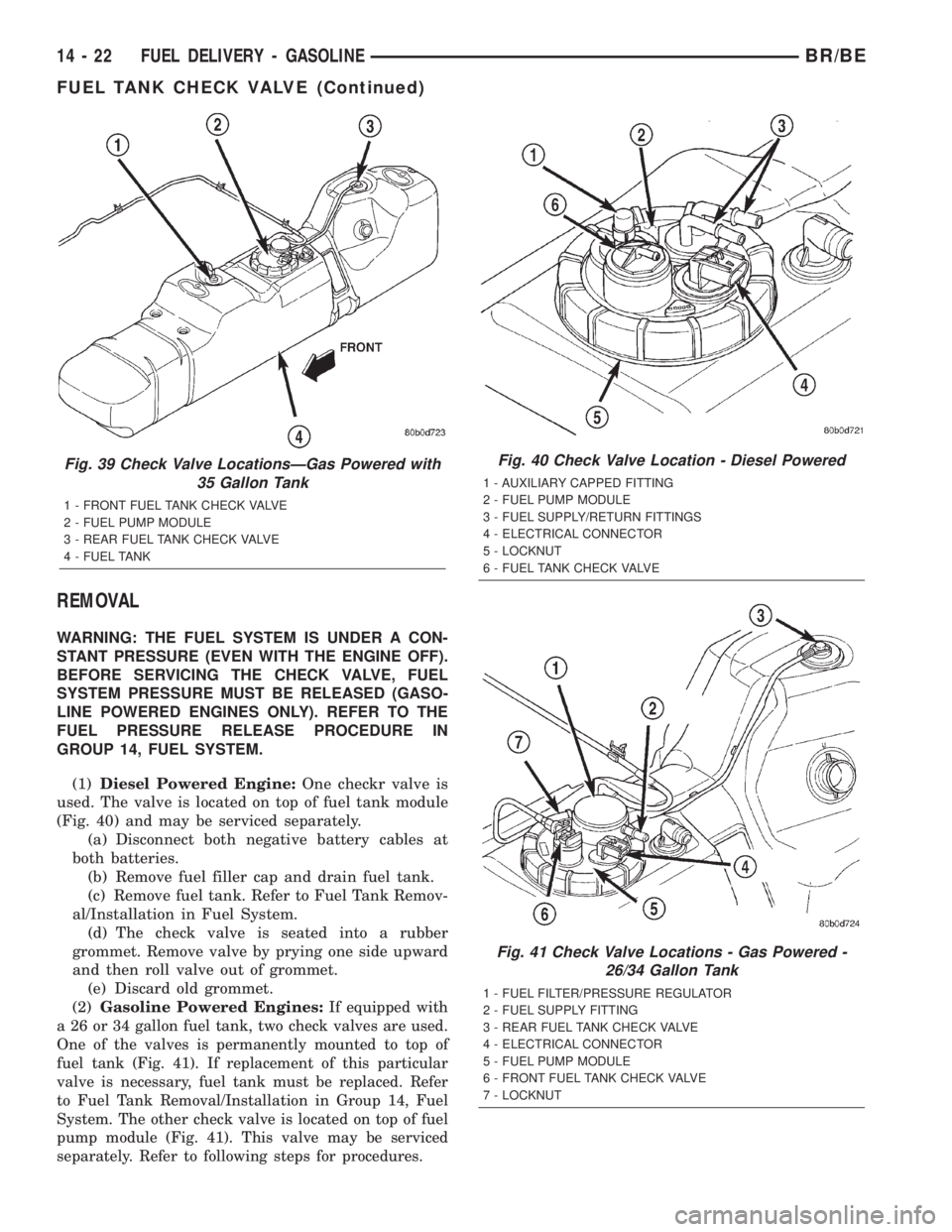
(1)Diesel Powered Engine:One checkr valve is
used. The valve is located on top of fuel tank module
(Fig. 40) and may be serviced separately.
(a) Disconnect both negative battery cables at
both batteries.
(b) Remove fuel filler cap and drain fuel tank.
(c) Remove fuel tank. Refer to Fuel Tank Remov-
al/Installation in Fuel System.
(d) The check valve is seated into a rubber
grommet. Remove valve by prying one side upward
and then roll valve out of grommet.
(e) Discard old grommet.
(2)Gasoline Powered Engines:
If equipped with
a 26 or 34 gallon fuel tank, two check valves are used.
One of the valves is permanently mounted to top of
fuel tank (Fig. 41). If replacement of this particular
valve is necessary, fuel tank must be replaced. Refer
to Fuel Tank Removal/Installation in Group 14, Fuel
System. The other check valve is located on top of fuel
pump module (Fig. 41). This valve may be serviced
separately. Refer to following steps for procedures.
Fig. 39 Check Valve LocationsÐGas Powered with
35 Gallon Tank
1 - FRONT FUEL TANK CHECK VALVE
2 - FUEL PUMP MODULE
3 - REAR FUEL TANK CHECK VALVE
4 - FUEL TANK
Fig. 40 Check Valve Location - Diesel Powered
1 - AUXILIARY CAPPED FITTING
2 - FUEL PUMP MODULE
3 - FUEL SUPPLY/RETURN FITTINGS
4 - ELECTRICAL CONNECTOR
5 - LOCKNUT
6 - FUEL TANK CHECK VALVE
Fig. 41 Check Valve Locations - Gas Powered -
26/34 Gallon Tank
1 - FUEL FILTER/PRESSURE REGULATOR
2 - FUEL SUPPLY FITTING
3 - REAR FUEL TANK CHECK VALVE
4 - ELECTRICAL CONNECTOR
5 - FUEL PUMP MODULE
6 - FRONT FUEL TANK CHECK VALVE
7 - LOCKNUT
14 - 22 FUEL DELIVERY - GASOLINEBR/BE
FUEL TANK CHECK VALVE (Continued)
Page 1323 of 2255
QUICK CONNECT FITTING
DESCRIPTION
Different types of quick-connect fittings are used to
attach various fuel system components, lines and
tubes. These are: a single-tab type, a two-tab type or
a plastic retainer ring type. Some are equipped with
safety latch clips. Some may require the use of a spe-
cial tool for disconnection and removal. Refer to
Quick-Connect Fittings Removal/Installation for more
information.
CAUTION: The interior components (o-rings, clips)
of quick-connect fittings are not serviced sepa-
rately, but new plastic spacers are available for
some types. If service parts are not available, do
not attempt to repair the damaged fitting or fuel line
(tube). If repair is necessary, replace the complete
fuel line (tube) assembly.
STANDARD PROCEDURE - QUICK-CONNECT
FITTINGS
Also refer to Fuel Tubes/Lines/Hoses and Clamps.
Different types of quick-connect fittings are used to
attach various fuel system components, lines and
tubes. These are: a single-tab type, a two-tab type or
a plastic retainer ring type. Safety latch clips are
used on certain components/lines. Certain fittings
may require use of a special tool for disconnection.
DISCONNECTING
WARNING: THE FUEL SYSTEM IS UNDER A CON-
STANT PRESSURE (EVEN WITH ENGINE OFF).
BEFORE SERVICING ANY FUEL SYSTEM HOSE,
FITTING OR LINE, FUEL SYSTEM PRESSURE MUST
BE RELEASED. REFER TO FUEL SYSTEM PRES-
SURE RELEASE PROCEDURE.
CAUTION: The interior components (o-rings, spac-
ers) of some types of quick-connect fitting are not
serviced separately. If service parts are not avail-
able, do not attempt to repair a damaged fitting or
fuel line. If repair is necessary, replace complete
fuel line assembly.(1) Perform fuel pressure release procedure. Refer
to Fuel Pressure Release Procedure.
(2) Disconnect negative battery cable from battery.
(3) Clean fitting of any foreign material before dis-
assembly.
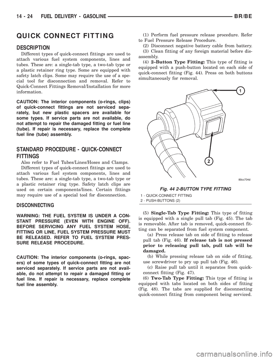
(4)2±Button Type Fitting:This type of fitting is
equipped with a push-button located on each side of
quick-connect fitting (Fig. 44). Press on both buttons
simultaneously for removal.
(5)Single-Tab Type Fitting:This type of fitting
is equipped with a single pull tab (Fig. 45). The tab
is removable. After tab is removed, quick-connect fit-
ting can be separated from fuel system component.
(a) Press release tab on side of fitting to release
pull tab (Fig. 46).If release tab is not pressed
prior to releasing pull tab, pull tab will be
damaged.
(b) While pressing release tab on side of fitting,
use screwdriver to pry up pull tab (Fig. 46).
(c) Raise pull tab until it separates from quick-
connect fitting (Fig. 47).
(6)Two-Tab Type Fitting:This type of fitting is
equipped with tabs located on both sides of fitting
(Fig. 48). The tabs are supplied for disconnecting
quick-connect fitting from component being serviced.
Fig. 44 2-BUTTON TYPE FITTING
1 - QUICK-CONNECT FITTING
2 - PUSH-BUTTONS (2)
14 - 24 FUEL DELIVERY - GASOLINEBR/BE
Page 1345 of 2255

around 70ÉF, the resistance of the heating element is
approximately 4.5 ohms. As the sensor's temperature
increases, resistance in the heater element increases.
This allows the heater to maintain the optimum
operating temperature of approximately 930É-1100ÉF
(500É-600É C). Although the sensors operate the
same, there are physical differences, due to the envi-
ronment that they operate in, that keep them from
being interchangeable.
Maintaining correct sensor temperature at all
times allows the system to enter into closed loop
operation sooner. Also, it allows the system to remain
in closed loop operation during periods of extended
idle.
In Closed Loop operation, the PCM monitors cer-
tain O2 sensor input(s) along with other inputs, and
adjusts the injector pulse width accordingly. During
Open Loop operation, the PCM ignores the O2 sensor
input. The PCM adjusts injector pulse width based
on preprogrammed (fixed) values and inputs from
other sensors.
Upstream Sensors:Two upstream sensors are
used (1/1 and 2/1). The 1/1 sensor is the first sensor
to receive exhaust gases from the #1 cylinder. They
provide an input voltage to the PCM. The input tells
the PCM the oxygen content of the exhaust gas. The
PCM uses this information to fine tune fuel delivery
to maintain the correct oxygen content at the down-
stream oxygen sensors. The PCM will change the air/
fuel ratio until the upstream sensors input a voltage
that the PCM has determined will make the down-
stream sensors output (oxygen content) correct.
The upstream oxygen sensors also provide an input
to determine mini-catalyst efficiency. Main catalytic
convertor efficiency is not calculated with this pack-
age.
Downstream Sensors:Two downstream sensors
are used (1/2 and 2/2). The downstream sensors are
used to determine the correct air-fuel ratio. As the
oxygen content changes at the downstream sensor,
the PCM calculates how much air-fuel ratio change is
required. The PCM then looks at the upstream oxy-
gen sensor voltage, and changes fuel delivery until
the upstream sensor voltage changes enough to cor-
rect the downstream sensor voltage (oxygen content).
The downstream oxygen sensors also provide an
input to determine mini-catalyst efficiency. Main cat-
alytic convertor efficiency is not calculated with this
package.
Medium and Heavy Duty 8.0L V-10 Engine:
Four oxygen sensors are used (2 upstream, 1 pre-cat-
alyst and 1 post-catalyst). The upstream sensors (1/1
and 2/1) will fine-tune the air-fuel ratio through the
Powertrain Control Module (PCM). The pre-catalyst
(1/2) and post-catalyst (1/3) sensors will determine
catalytic convertor efficiency (efficiency of the maincatalytic convertor). This is also done through the
PCM.
Heavy Duty 5.9L Engine:Downstream sensors
are not used with this emissions package, meaning
catalytic convertor efficiency is not calculated with
this package. Two upstream sensors are used. The
left upstream sensor (1/1) will monitor cylinders 1, 3,
5 and 7. The right upstream sensor (2/1) will monitor
cylinders 2, 4, 6 and 8. The PCM monitors the oxy-
gen content of the sensors, and will fine-tune the air-
fuel ratio.
Engines equipped with either a downstream sen-
sor(s), or a post-catalytic sensor, will monitor cata-
lytic convertor efficiency. If efficiency is below
emission standards, the Malfunction Indicator Lamp
(MIL) will be illuminated and a Diagnostic Trouble
Code (DTC) will be set. Refer to Monitored Systems
in Emission Control Systems for additional informa-
tion.
REMOVAL
Never apply any type of grease to the oxygen
sensor electrical connector, or attempt any sol-
dering of the sensor wiring harness.
The O2S (oxygen sensors) are numbered 1/1, 1/2,
1/3, 2/1 and 2/2.
On HDC engines, the pre-catalyst/post catalyst
O2S sensors are located at the inlet and outlet ends
of the catalytic converter (Fig. 38).
The 1/1 and 2/1 sensors are located before the
mini-cats (Fig. 39). The 1/2 and 2/2 sensors are
located after the mini-cats (Fig. 39).
WARNING: THE EXHAUST MANIFOLD, EXHAUST
PIPES AND CATALYTIC CONVERTER BECOME
VERY HOT DURING ENGINE OPERATION. ALLOW
ENGINE TO COOL BEFORE REMOVING OXYGEN
SENSOR.
Fig. 38 Pre-catalyst/Post catalyst Oxygen SensorsÐ
HDC Engines
1 - POST CATALYST OXYGEN SENSOR (1/3)
2 - PRE-CATALYST OXYGEN SENSOR (1/2)
14 - 46 FUEL INJECTION - GASOLINEBR/BE
O2 SENSOR (Continued)
Page 1354 of 2255
FUEL DELIVERY - DIESEL
DESCRIPTION
DESCRIPTION - DIESEL FUEL DELIVERY
SYSTEM
The fuel system on the Cummins 24 valveÐTurbo
Diesel Engine uses anelectronically controlled
fuel injection pump with three control modules.
Also refer to the Powertrain Control Module (PCM)
or Engine Control Module sections.
Some fuel system components are shown in (Fig.
1).
The fuel delivery system consists of the:
²Accelerator pedal
²Air cleaner housing/element
²Fuel drain manifold (passage)
²Fuel filter/water separator
²Fuel heater
²Fuel heater relay
²Fuel transfer (lift) pump
²Fuel injection pump
²Fuel injectors
²Fuel heater temperature sensor
²Fuel tank
²Fuel tank filler/vent tube assembly²Fuel tank filler tube cap
²Fuel tank module containing the rollover valve,
fuel gauge sending unit (fuel level sensor) and a sep-
arate fuel filter located at bottom of tank module
²Fuel tubes/lines/hoses
²High-pressure fuel injector lines
²In-tank fuel filter (at bottom of fuel tank mod-
ule)
²Low-pressure fuel supply lines
²Low-pressure fuel return line
²Overflow valve
²Quick-connect fittings
²Throttle cable
²Water draining
OPERATION
WARNING: HIGH-PRESSURE FUEL LINES DELIVER
DIESEL FUEL UNDER EXTREME PRESSURE FROM
THE INJECTION PUMP TO THE FUEL INJECTORS.
THIS MAY BE AS HIGH AS 120,000 KPA (17,405
PSI). USE EXTREME CAUTION WHEN INSPECTING
FOR HIGH-PRESSURE FUEL LEAKS. INSPECT FOR
HIGH-PRESSURE FUEL LEAKS WITH A SHEET OF
CARDBOARD. HIGH FUEL INJECTION PRESSURE
CAN CAUSE PERSONAL INJURY IF CONTACT IS
MADE WITH THE SKIN.
BR/BEFUEL DELIVERY - DIESEL 14 - 55
Page 1360 of 2255
STANDARD PROCEDURE
STANDARD PROCEDURES - WATER DRAINING
AT FUEL FILTER
Refer to Fuel Filter/Water Separator removal/in-
stallation for procedures.
STANDARD PROCEDURES - CLEANING FUEL
SYSTEM PARTS
CAUTION: Cleanliness cannot be overemphasized
when handling or replacing diesel fuel system com-
ponents. This especially includes the fuel injectors,
high-pressure fuel lines and fuel injection pump.
Very tight tolerances are used with these parts. Dirt
contamination could cause rapid part wear and pos-
sible plugging of fuel injector nozzle tip holes. This
in turn could lead to possible engine misfire.
Always wash/clean any fuel system component
thoroughly before disassembly and then air dry.
Cap or cover any open part after disassembly.
Before assembly, examine each part for dirt, grease
or other contaminants and clean if necessary. When
installing new parts, lubricate them with clean
engine oil or clean diesel fuel only.
STANDARD PROCEDURE - AIR BLEED
A certain amount of air becomes trapped in the
fuel system when fuel system components on the
supply and/or high-pressure side are serviced or
replaced. Primary air bleeding is accomplished using
the electric fuel transfer (lift) pump. If the vehicle
has been allowed to run completely out of fuel, the
fuel injectors must also be bled as the fuel injection
pumpis notself-bleeding (priming).
Servicing or replacing components on the fuel
return side will not require air bleeding.
WARNING: DO NOT BLEED AIR FROM THE FUEL
SYSTEM OF A HOT ENGINE.
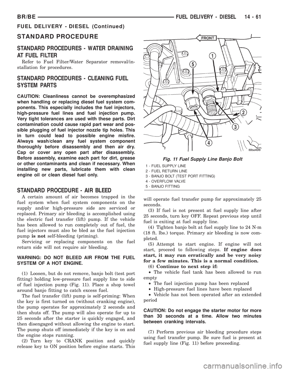
(1) Loosen, but do not remove, banjo bolt (test port
fitting) holding low-pressure fuel supply line to side
of fuel injection pump (Fig. 11). Place a shop towel
around banjo fitting to catch excess fuel.
The fuel transfer (lift) pump is self-priming: When
the key is first turned on (without cranking engine),
the pump operates for approximately 2 seconds and
then shuts off. The pump will also operate for up to
25 seconds after the starter is quickly engaged, and
then disengaged without allowing the engine to start.
The pump shuts off immediately if the key is on and
the engine stops running.
(2) Turn key to CRANK position and quickly
release key to ON position before engine starts. Thiswill operate fuel transfer pump for approximately 25
seconds.
(3) If fuel is not present at fuel supply line after
25 seconds, turn key OFF. Repeat previous step until
fuel is exiting at fuel supply line.
(4) Tighten banjo bolt at fuel supply line to 24 N´m
(18 ft. lbs.) torque. Primary air bleeding is now com-
pleted.
(5) Attempt to start engine. If engine will not
start, proceed to following steps.If engine does
start, it may run erratically and be very noisy
for a few minutes. This is a normal condition.
(6)Continue to next step if:
²The vehicle fuel tank has been allowed to run
empty
²The fuel injection pump has been replaced
²High-pressure fuel lines have been replaced
²Vehicle has not been operated after an extended
period
CAUTION: Do not engage the starter motor for more
than 30 seconds at a time. Allow two minutes
between cranking intervals.
(7) Perform previous air bleeding procedure steps
using fuel transfer pump. Be sure fuel is present at
fuel supply line (Fig. 11) before proceeding.
Fig. 11 Fuel Supply Line Banjo Bolt
1 - FUEL SUPPLY LINE
2 - FUEL RETURN LINE
3 - BANJO BOLT (TEST PORT FITTING)
4 - OVERFLOW VALVE
5 - BANJO FITTING
BR/BEFUEL DELIVERY - DIESEL 14 - 61
FUEL DELIVERY - DIESEL (Continued)
Page 1361 of 2255
(8) Crank the engine for 30 seconds at a time to
allow air trapped in the injection pump to vent out
the drain manifold.
WARNING: THE FUEL INJECTION PUMP SUPPLIES
EXTREMELY HIGH FUEL PRESSURE TO EACH INDI-
VIDUAL INJECTOR THROUGH THE HIGH-PRES-
SURE LINES. FUEL UNDER THIS AMOUNT OF
PRESSURE CAN PENETRATE THE SKIN AND
CAUSE PERSONAL INJURY. WEAR SAFETY GOG-
GLES AND ADEQUATE PROTECTIVE CLOTHING
AND AVOID CONTACT WITH FUEL SPRAY WHEN
BLEEDING HIGH-PRESSURE FUEL LINES.
WARNING: ENGINE MAY START WHILE CRANKING
STARTER MOTOR.
Engine may start, may run erratically and be
very noisy for a few minutes. This is a normal
condition.
(9) Thoroughly clean area around injector fittings
where they join injector connector tubes.
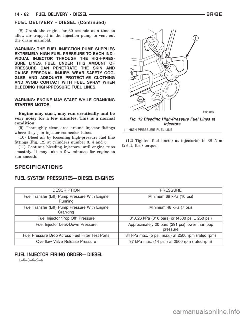
(10) Bleed air by loosening high-pressure fuel line
fittings (Fig. 12) at cylinders number 3, 4 and 5.
(11) Continue bleeding injectors until engine runs
smoothly. It may take a few minutes for engine to
run smooth.(12) Tighten fuel line(s) at injector(s) to 38 N´m
(28 ft. lbs.) torque.
SPECIFICATIONS
FUEL SYSTEM PRESSURESÐDIESEL ENGINES
DESCRIPTION PRESSURE
Fuel Transfer (Lift) Pump Pressure With Engine
RunningMinimum 69 kPa (10 psi)
Fuel Transfer (Lift) Pump Pressure With Engine
CrankingMinimum 48 kPa (7 psi)
Fuel Injector ªPop Offº Pressure 31,026 kPa (310 bars) or (4500 psi 250 psi)
Fuel Injector Leak-Down Pressure Approximately 20 bars (291 psi) lower than pop
pressure
Fuel Pressure Drop Across Fuel Filter Test Ports 34 kPa max. (5 psi. max.) at 2500 rpm (rated rpm)
Overflow Valve Release Pressure 97 kPa max. (14 psi.) at 2500 rpm (rated rpm)
FUEL INJECTOR FIRING ORDERÐDIESEL
1±5±3±6±2±4
Fig. 12 Bleeding High-Pressure Fuel Lines at
Injectors
1 - HIGH-PRESSURE FUEL LINE
14 - 62 FUEL DELIVERY - DIESELBR/BE
FUEL DELIVERY - DIESEL (Continued)