2002 DODGE RAM ECO mode
[x] Cancel search: ECO modePage 5 of 2255
BODY CODE PLATE
DESCRIPTION
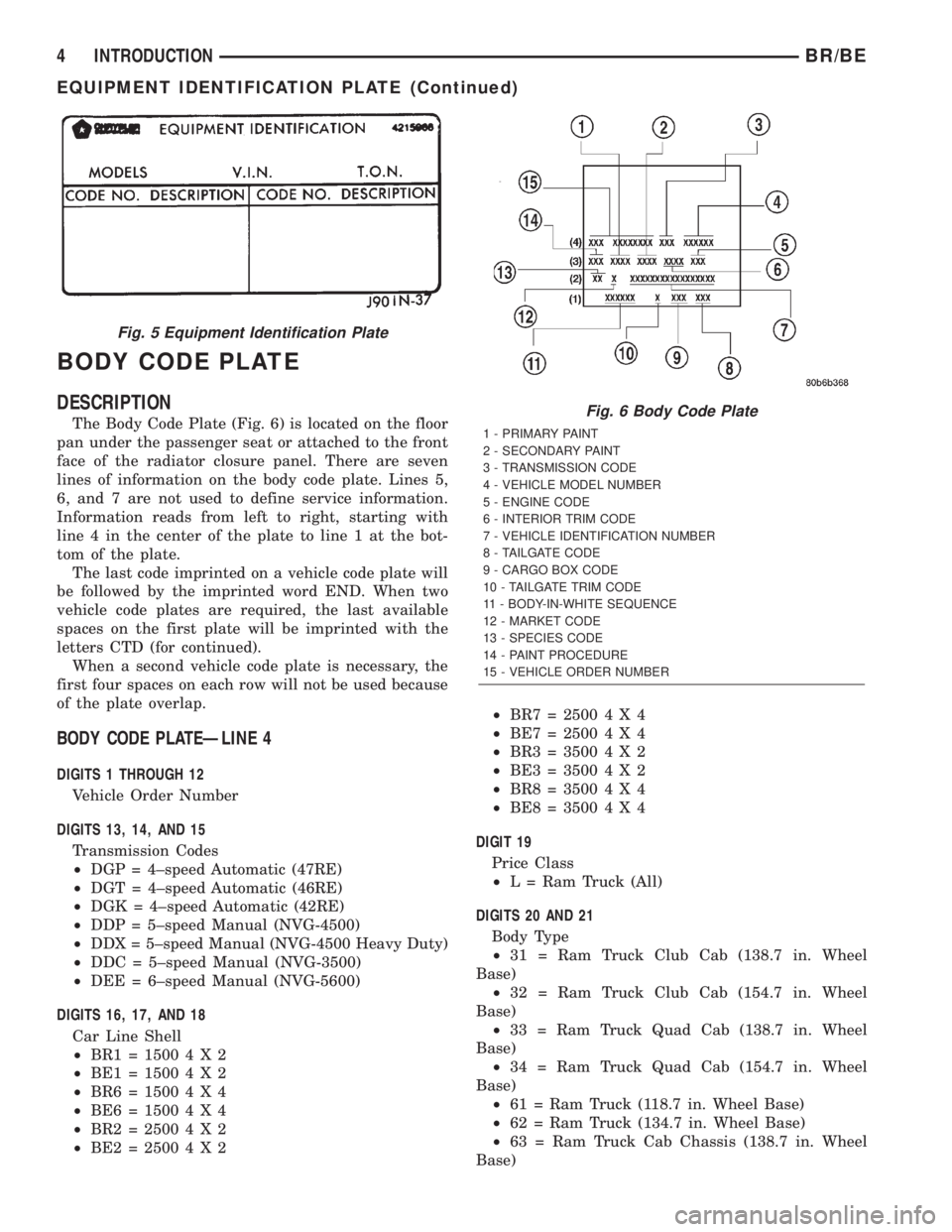
The Body Code Plate (Fig. 6) is located on the floor
pan under the passenger seat or attached to the front
face of the radiator closure panel. There are seven
lines of information on the body code plate. Lines 5,
6, and 7 are not used to define service information.
Information reads from left to right, starting with
line 4 in the center of the plate to line 1 at the bot-
tom of the plate.
The last code imprinted on a vehicle code plate will
be followed by the imprinted word END. When two
vehicle code plates are required, the last available
spaces on the first plate will be imprinted with the
letters CTD (for continued).
When a second vehicle code plate is necessary, the
first four spaces on each row will not be used because
of the plate overlap.
BODY CODE PLATEÐLINE 4
DIGITS 1 THROUGH 12
Vehicle Order Number
DIGITS 13, 14, AND 15
Transmission Codes
²DGP = 4±speed Automatic (47RE)
²DGT = 4±speed Automatic (46RE)
²DGK = 4±speed Automatic (42RE)
²DDP = 5±speed Manual (NVG-4500)
²DDX = 5±speed Manual (NVG-4500 Heavy Duty)
²DDC = 5±speed Manual (NVG-3500)
²DEE = 6±speed Manual (NVG-5600)
DIGITS 16, 17, AND 18
Car Line Shell
²BR1=15004X2
²BE1=15004X2
²BR6=15004X4
²BE6=15004X4
²BR2=25004X2
²BE2=25004X2²BR7=25004X4
²BE7=25004X4
²BR3=35004X2
²BE3=35004X2
²BR8=35004X4
²BE8=35004X4
DIGIT 19
Price Class
²L = Ram Truck (All)
DIGITS 20 AND 21
Body Type
²31 = Ram Truck Club Cab (138.7 in. Wheel
Base)
²32 = Ram Truck Club Cab (154.7 in. Wheel
Base)
²33 = Ram Truck Quad Cab (138.7 in. Wheel
Base)
²34 = Ram Truck Quad Cab (154.7 in. Wheel
Base)
²61 = Ram Truck (118.7 in. Wheel Base)
²62 = Ram Truck (134.7 in. Wheel Base)
²63 = Ram Truck Cab Chassis (138.7 in. Wheel
Base)
Fig. 5 Equipment Identification Plate
Fig. 6 Body Code Plate
1 - PRIMARY PAINT
2 - SECONDARY PAINT
3 - TRANSMISSION CODE
4 - VEHICLE MODEL NUMBER
5 - ENGINE CODE
6 - INTERIOR TRIM CODE
7 - VEHICLE IDENTIFICATION NUMBER
8 - TAILGATE CODE
9 - CARGO BOX CODE
10 - TAILGATE TRIM CODE
11 - BODY-IN-WHITE SEQUENCE
12 - MARKET CODE
13 - SPECIES CODE
14 - PAINT PROCEDURE
15 - VEHICLE ORDER NUMBER
4 INTRODUCTIONBR/BE
EQUIPMENT IDENTIFICATION PLATE (Continued)
Page 19 of 2255

DESCRIPTION - AUTOMATIC TRANSMISSION
FLUID
NOTE: Refer to the maintenance schedules in this
group for the recommended maintenance (fluid/filter
change) intervals for this transmission.
NOTE: Refer to Service Procedures in this group for
fluid level checking procedures.
MopartATF +4, type 9602, Automatic Transmis-
sion Fluid is the recommended fluid for
DaimlerChrysler automatic transmissions.
Dexron II fluid IS NOT recommended. Clutch
chatter can result from the use of improper
fluid.
MopartATF +4, type 9602, Automatic Transmis-
sion Fluid when new is red in color. The ATF is dyed
red so it can be identified from other fluids used in
the vehicle such as engine oil or antifreeze. The red
color is not permanent and is not an indicator of fluid
condition. As the vehicle is driven, the ATF will begin
to look darker in color and may eventually become
brown.This is normal.A dark brown/black fluid
accompanied with a burnt odor and/or deterioration
in shift quality may indicate fluid deterioration or
transmission component failure.
FLUID ADDITIVES
DaimlerChrysler strongly recommends against the
addition of any fluids to the transmission, other than
those automatic transmission fluids listed above.
Exceptions to this policy are the use of special dyes
to aid in detecting fluid leaks.
Various ªspecialº additives and supplements exist
that claim to improve shift feel and/or quality. These
additives and others also claim to improve converter
clutch operation and inhibit overheating, oxidation,
varnish, and sludge. These claims have not been sup-
ported to the satisfaction of DaimlerChrysler and
these additivesmust not be used.The use of trans-
mission ªsealersº should also be avoided, since they
may adversely affect the integrity of transmission
seals.
OPERATION - AUTOMATIC TRANSMISSION
FLUID
The automatic transmission fluid is selected based
upon several qualities. The fluid must provide a high
level of protection for the internal components by
providing a lubricating film between adjacent metal
components. The fluid must also be thermally stable
so that it can maintain a consistent viscosity through
a large temperature range. If the viscosity stays con-
stant through the temperature range of operation,transmission operation and shift feel will remain con-
sistent. Transmission fluid must also be a good con-
ductor of heat. The fluid must absorb heat from the
internal transmission components and transfer that
heat to the transmission case.
FLUID CAPACITIES
SPECIFICATIONS
FLUID CAPACITIES
DESCRIPTION SPECIFICATION
FUEL TANK
2500 Series Club Cab
and Quad Cab with 6.5'
Short Box129 L (34 gal.)*****
All 8' Long Box 132 L (35 gal.)*****
All Cab/Chassis Models 132 L (35 gal.)*****
ENGINE OIL WITH FILTER
5.9L 4.7 L (5.0 qts.)
8.0L 6.6 L (7.0 qts.)
5.9L DIESEL 10.4 L (11.0 qts.)
COOLING SYSTEM
5.9L 19 L (20 qts.)****
8.0L 24.5 L (26.0 qts.)****
5.9L DIESEL 22.7 L (24.0 qts.)****
POWER STEERING
Power steering fluid capacities are dependent on
engine/chassis options as well as steering gear/cooler
options. Depending on type and size of internal
cooler, length and inside diameter of cooler lines, or
use of an auxiliary cooler, these capacities may vary.
Refer to 19, Steering for proper fill and bleed
procedures.
AUTOMATIC TRANSMISSION
Service Fill - 46RE 3.8 L (4.0 qts.)
O-haul - 46RE 9-9.5L (19-20 pts.)*
Service Fill - 47RE 3.8 L (4.0 qts.)
O-haul - 47RE 14-16 L (29-33 pts.)*
0 - 6 LUBRICATION & MAINTENANCEBR/BE
FLUID TYPES (Continued)
Page 86 of 2255
AXLE SHAFT SEALS
REMOVAL
(1) Remove hub bearings and axle shafts.
(2) Remove axle shaft seal from the differential
housing with a long drift or punch.Be careful not
to damage housing.
(3) Clean the inside perimeter of the differential
housing with fine crocus cloth.
INSTALLATION
(1) Apply a light film of oil to the inside lip of the
new axle shaft seal.
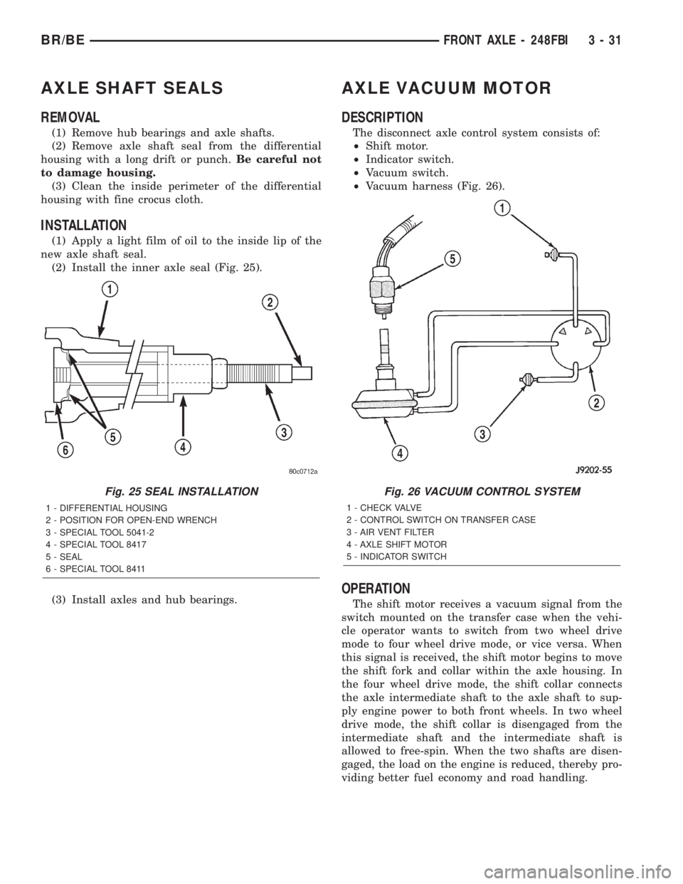
(2) Install the inner axle seal (Fig. 25).
(3) Install axles and hub bearings.
AXLE VACUUM MOTOR
DESCRIPTION
The disconnect axle control system consists of:
²Shift motor.
²Indicator switch.
²Vacuum switch.
²Vacuum harness (Fig. 26).
OPERATION
The shift motor receives a vacuum signal from the
switch mounted on the transfer case when the vehi-
cle operator wants to switch from two wheel drive
mode to four wheel drive mode, or vice versa. When
this signal is received, the shift motor begins to move
the shift fork and collar within the axle housing. In
the four wheel drive mode, the shift collar connects
the axle intermediate shaft to the axle shaft to sup-
ply engine power to both front wheels. In two wheel
drive mode, the shift collar is disengaged from the
intermediate shaft and the intermediate shaft is
allowed to free-spin. When the two shafts are disen-
gaged, the load on the engine is reduced, thereby pro-
viding better fuel economy and road handling.
Fig. 25 SEAL INSTALLATION
1 - DIFFERENTIAL HOUSING
2 - POSITION FOR OPEN-END WRENCH
3 - SPECIAL TOOL 5041-2
4 - SPECIAL TOOL 8417
5 - SEAL
6 - SPECIAL TOOL 8411
Fig. 26 VACUUM CONTROL SYSTEM
1 - CHECK VALVE
2 - CONTROL SWITCH ON TRANSFER CASE
3 - AIR VENT FILTER
4 - AXLE SHIFT MOTOR
5 - INDICATOR SWITCH
BR/BEFRONT AXLE - 248FBI 3 - 31
Page 215 of 2255
(7) Install caliper, (Refer to 5 - BRAKES/HY-
DRAULIC/MECHANICAL/DISC BRAKE CALIPERS
- INSTALLATION) (Refer to 5 - BRAKES/HYDRAU-
LIC/MECHANICAL/DISC BRAKE CALIPERS -
INSTALLATION).
(8) Install wheel and tire assemblies and lower
vehicle, (Refer to 22 - TIRES/WHEELS/WHEELS -
STANDARD PROCEDURE).
(9) Apply brakes several times to seat caliper pis-
tons and brake shoes and obtain firm pedal.
(10) Top off master cylinder fluid level.
INSTALLATION - FRONT
(1) Bottom pistons in caliper bore with C-clamp.
Place an old brake shoe between a C-clamp and cal-
iper piston.
(2) Clean caliper mounting adapter and anti-rattle
springs.
(3) Lubricate anti-rattle springs with Mopar brake
grease.
(4) Install anti-rattle springs.
NOTE: Anti-rattle springs are not interchangeable.
(5) Install inboard brake shoe in adapter.
(6) Install outboard brake shoe in adapter.
(7) Tilt the bottom of the caliper over rotor and
under adapter. Then push the top of the caliper down
onto the adapter.
(8) Install caliper, (Refer to 5 - BRAKES/HY-
DRAULIC/MECHANICAL/DISC BRAKE CALIPERS
- INSTALLATION).
(9) Install wheel and tire assemblies and lower
vehicle, (Refer to 22 - TIRES/WHEELS/WHEELS -
STANDARD PROCEDURE).
(10) Apply brakes several times to seat caliper pis-
tons and brake shoes and obtain firm pedal.
(11) Top off master cylinder fluid level.
MASTER CYLINDER
DESCRIPTION
A two-piece master cylinder is used on all models.
The cylinder body containing the primary and sec-
ondary pistons is made of aluminum. The removable
fluid reservoir is made of nylon reinforced with glass
fiber. The reservoir stores reserve brake fluid for the
hydraulic brake circuits. The reservoir is the only
serviceable component.
The fluid compartments of the nylon reservoir are
interconnected to permit fluid level equalization.
However, the equalization feature does not affect cir-
cuit separation in the event of a front or rear brake
malfunction. The reservoir compartments will retain
enough fluid to operate the functioning hydraulic cir-
cuit.Care must be exercised when removing/installing
the master cylinder connecting lines. The threads in
the cylinder fluid ports can be damaged if care is not
exercised. Start all brake line fittings by hand to
avoid cross threading.
The cylinder reservoir can be replaced when neces-
sary. However, the aluminum body section of the
master cylinder is not a repairable component.
NOTE: If diagnosis indicates that an internal mal-
function has occurred, the aluminum body section
must be replaced as an assembly.
OPERATION
The master cylinder bore contains a primary and
secondary piston. The primary piston supplies
hydraulic pressure to the front brakes. The secondary
piston supplies hydraulic pressure to the rear brakes.
DIAGNOSIS AND TESTING - MASTER
CYLINDER/POWER BOOSTER
(1) Start engine and check booster vacuum hose
connections. A hissing noise indicates vacuum leak.
Correct any vacuum leak before proceeding.
(2) Stop engine and shift transmission into Neu-
tral.
(3) Pump brake pedal until all vacuum reserve in
booster is depleted.
(4) Press and hold brake pedal under light foot
pressure. The pedal should hold firm, if the pedal
falls away master cylinder is faulty (internal leak-
age).
(5) Start engine and note pedal action. It should
fall away slightly under light foot pressure then hold
firm. If no pedal action is discernible, power booster,
vacuum supply, or vacuum check valve is faulty. Pro-
ceed to the POWER BOOSTER VACUUM TEST.
(6) If the POWER BOOSTER VACUUM TEST
passes, rebuild booster vacuum reserve as follows:
Release brake pedal. Increase engine speed to 1500
rpm, close the throttle and immediately turn off igni-
tion to stop engine.
(7) Wait a minimum of 90 seconds and try brake
action again. Booster should provide two or more vac-
uum assisted pedal applications. If vacuum assist is
not provided, booster is faulty.
POWER BOOSTER VACUUM TEST
(1) Connect vacuum gauge to booster check valve
with short length of hose and T-fitting (Fig. 47).
(2) Start and run engine at curb idle speed for one
minute.
(3) Observe the vacuum supply. If vacuum supply
is not adequate, repair vacuum supply.
5 - 26 BRAKES - BASEBR/BE
BRAKE PADS/SHOES (Continued)
Page 250 of 2255
COOLING
TABLE OF CONTENTS
page page
COOLING
DESCRIPTION
DESCRIPTION - COOLING SYSTEM FLOW -
5.9L ENGINE..........................1
DESCRIPTIONÐCOOLING SYSTEM FLOW -
5.9L DIESEL..........................2
DESCRIPTIONÐHOSE CLAMPS...........4
OPERATION
OPERATIONÐHOSE CLAMPS............4
OPERATIONÐCOOLING SYSTEM.........4
DIAGNOSIS AND TESTING
DIAGNOSIS AND TESTING - PRELIMINARY
CHECKS.............................4
DIAGNOSIS AND TESTINGÐON-BOARD
DIAGNOSTICS (OBD)...................5
DIAGNOSIS AND TESTING - COOLING
SYSTEM LEAKS.......................5
DIAGNOSIS AND TESTING - COOLING
SYSTEM GAS ENGINE..................7
DIAGNOSIS AND TESTING - COOLING
SYSTEM DIESEL ENGINE...............13
STANDARD PROCEDURE
STANDARD PROCEDURE - DRAINING
COOLING SYSTEM 5.9L/8.0L ENGINES....15STANDARD PROCEDUREÐDRAINING
COOLING SYSTEM 5.9L DIESEL ENGINE . . . 15
STANDARD PROCEDURE - REFILLING
COOLING SYSTEM 5.9L/8.0L ENGINES....16
STANDARD PROCEDUREÐREFILLING
COOLING SYSTEM 5.9L DIESEL ENGINE . . . 16
STANDARD PROCEDURE - ADDING
ADDITIONAL COOLANT.................16
STANDARD PROCEDUREÐCOOLANT
LEVEL CHECK........................16
STANDARD PROCEDURE - COOLING
SYSTEM CLEANING/REVERSE FLUSHING . . 17
STANDARD PROCEDURE - COOLANT
SELECTION - ADDITIVES...............17
SPECIFICATIONS
TORQUE............................18
SPECIAL TOOLS
COOLING...........................18
ACCESSORY DRIVE......................19
ENGINE...............................38
TRANSMISSION.........................78
COOLING
DESCRIPTION
DESCRIPTION - COOLING SYSTEM FLOW -
5.9L ENGINE
The cooling system regulates engine operating tem-
perature. It allows the engine to reach normal oper-
ating temperature as quickly as possible. It also
maintains normal operating temperature and pre-
vents overheating.The cooling system also provides a means of heat-
ing the passenger compartment and cooling the auto-
matic transmission fluid (if equipped). The cooling
system is pressurized and uses a centrifugal water
pump to circulate coolant throughout the system.
An optional factory installed maximum duty cool-
ing package is available on most models. This pack-
age will provide additional cooling capacity for
vehicles used under extreme conditions such as
trailer towing in high ambient temperatures (Fig. 1).
BR/BECOOLING 7 - 1
Page 253 of 2255
DESCRIPTIONÐHOSE CLAMPS
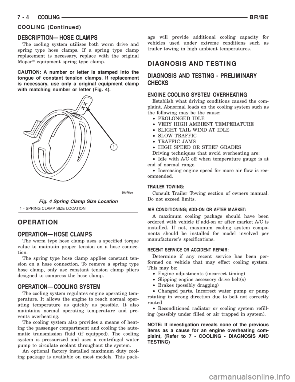
The cooling system utilizes both worm drive and
spring type hose clamps. If a spring type clamp
replacement is necessary, replace with the original
Mopartequipment spring type clamp.
CAUTION: A number or letter is stamped into the
tongue of constant tension clamps. If replacement
is necessary, use only a original equipment clamp
with matching number or letter (Fig. 4).
OPERATION
OPERATIONÐHOSE CLAMPS
The worm type hose clamp uses a specified torque
value to maintain proper tension on a hose connec-
tion.
The spring type hose clamp applies constant ten-
sion on a hose connection. To remove a spring type
hose clamp, only use constant tension clamp pliers
designed to compress the hose clamp.
OPERATIONÐCOOLING SYSTEM
The cooling system regulates engine operating tem-
perature. It allows the engine to reach normal oper-
ating temperature as quickly as possible. It also
maintains normal operating temperature and pre-
vents overheating.
The cooling system also provides a means of heat-
ing the passenger compartment and cooling the auto-
matic transmission fluid (if equipped). The cooling
system is pressurized and uses a centrifugal water
pump to circulate coolant throughout the system.
An optional factory installed maximum duty cool-
ing package is available on most models. This pack-age will provide additional cooling capacity for
vehicles used under extreme conditions such as
trailer towing in high ambient temperatures.
DIAGNOSIS AND TESTING
DIAGNOSIS AND TESTING - PRELIMINARY
CHECKS
ENGINE COOLING SYSTEM OVERHEATING
Establish what driving conditions caused the com-
plaint. Abnormal loads on the cooling system such as
the following may be the cause:
²PROLONGED IDLE
²VERY HIGH AMBIENT TEMPERATURE
²SLIGHT TAIL WIND AT IDLE
²SLOW TRAFFIC
²TRAFFIC JAMS
²HIGH SPEED OR STEEP GRADES
Driving techniques that avoid overheating are:
²Idle with A/C off when temperature gauge is at
end of normal range.
²Increasing engine speed for more air flow is rec-
ommended.
TRAILER TOWING:
Consult Trailer Towing section of owners manual.
Do not exceed limits.
AIR CONDITIONING; ADD-ON OR AFTER MARKET:
A maximum cooling package should have been
ordered with vehicle if add-on or after market A/C is
installed. If not, maximum cooling system compo-
nents should be installed for model involved per
manufacturer's specifications.
RECENT SERVICE OR ACCIDENT REPAIR:
Determine if any recent service has been per-
formed on vehicle that may effect cooling system.
This may be:
²Engine adjustments (incorrect timing)
²Slipping engine accessory drive belt(s)
²Brakes (possibly dragging)
²Changed parts. Incorrect water pump or pump
rotating in wrong direction due to belt not correctly
routed
²Reconditioned radiator or cooling system refill-
ing (possibly under filled or air trapped in system).
NOTE: If investigation reveals none of the previous
items as a cause for an engine overheating com-
plaint, (Refer to 7 - COOLING - DIAGNOSIS AND
TESTING)
Fig. 4 Spring Clamp Size Location
1 - SPRING CLAMP SIZE LOCATION
7 - 4 COOLINGBR/BE
COOLING (Continued)
Page 260 of 2255

CONDITION POSSIBLE CAUSES CORRECTION
COOLANT LOSS TO THE
GROUND WITHOUT PRESSURE
CAP BLOWOFF. GAUGE READING
HIGH OR HOT1. Coolant leaks in radiator, cooling
system hoses, water pump or
engine.1. Pressure test and repair as
necessary. (Refer to 7 - COOLING -
DIAGNOSIS AND TESTING).
DETONATION OR PRE-IGNITION
(NOT CAUSED BY IGNITION
SYSTEM). GAUGE MAY OR MAY
NOT BE READING HIGH1. Engine overheating. 1. Check reason for overheating
and repair as necessary.
2. Freeze point of coolant not
correct. Mixture is too rich or too
lean.2. Check coolant concentration.
(Refer to LUBRICATION &
MAINTENANCE/FLUID TYPES -
DESCRIPTION).
HOSE OR HOSES COLLAPSE
WHILE ENGINE IS RUNNING1. Vacuum created in cooling
system on engine cool-down is not
being relieved through coolant
reserve/overflow system.1. (a) Radiator cap relief valve
stuck. (Refer to 7 - COOLING/
ENGINE/RADIATOR PRESSURE
CAP - DIAGNOSIS AND TESTING).
Replace if necessary
(b) Hose between coolant
reserve/overflow tank and radiator is
kinked. Repair as necessary.
(c) Vent at coolant reserve/overflow
tank is plugged. Clean vent and
repair as necessary.
(d) Reserve/overflow tank is
internally blocked or plugged. Check
for blockage and repair as
necessary.
NOISY VISCOUS FAN/DRIVE 1. Fan blades loose. 1. Replace fan blade assembly.
(Refer to 7 - COOLING/ENGINE/
RADIATOR FAN - REMOVAL)
2. Fan blades striking a surrounding
object.2. Locate point of fan blade contact
and repair as necessary.
3. Air obstructions at radiator or air
conditioning condenser.3. Remove obstructions and/or
clean debris or insects from radiator
or A/C condenser.
4. Thermal viscous fan drive has
defective bearing.4. Replace fan drive. Bearing is not
serviceable. (Refer to 7 - COOLING/
ENGINE/FAN DRIVE VISCOUS
CLUTCH - REMOVAL).
5. A certain amount of fan noise
may be evident on models
equipped with a thermal viscous fan
drive. Some of this noise is normal.5. (Refer to 7 - COOLING/ENGINE/
FAN DRIVE VISCOUS CLUTCH -
DESCRIPTION) for an explanation
of normal fan noise.
BR/BECOOLING 7 - 11
COOLING (Continued)
Page 293 of 2255
INSTALLATION
(1) Install fan blade assembly to viscous fan drive.
Tighten mounting bolts to 23 N´m (17 ft. lbs.) torque.
(2) Position the fan shroud and fan blade/viscous
fan drive to the vehicle as an assembly.
(3) Install viscous fan drive assembly on fan hub
shaft (Fig. 7). Tighten mounting nut to 57 N´m (42 ft.
lbs.) torque.
(4) Install fan shroud bolts into position and
tighten the mounting bolts to 6 N´m (50 in. lbs.)
torque.
(5) Connect the battery negative cables.
NOTE:
Viscous Fan Drive Fluid Pump Out Requirement:
After installing a new viscous fan drive, bring the
engine speed up to approximately 2000 rpm and
hold for approximately two minutes. This will
ensure proper fluid distribution within the drive.
ENGINE BLOCK HEATER - 5.9L
DESCRIPTION
WARNING: DO NOT OPERATE ENGINE UNLESS
BLOCK HEATER CORD HAS BEEN DISCONNECTED
FROM POWER SOURCE AND SECURED IN PLACE.
THE POWER CORD MUST BE SECURED IN ITS
RETAINING CLIPS AND ROUTED AWAY FROM
EXHAUST MANIFOLDS AND MOVING PARTS.
An optional engine block heater is available on all
models. The heater is equipped with a power cord.
The heater is mounted in a core hole of the engine
cylinder block (in place of a freeze plug) with the
heating element immersed in engine coolant. The
cord is attached to an engine compartment compo-
nent with tie-straps.
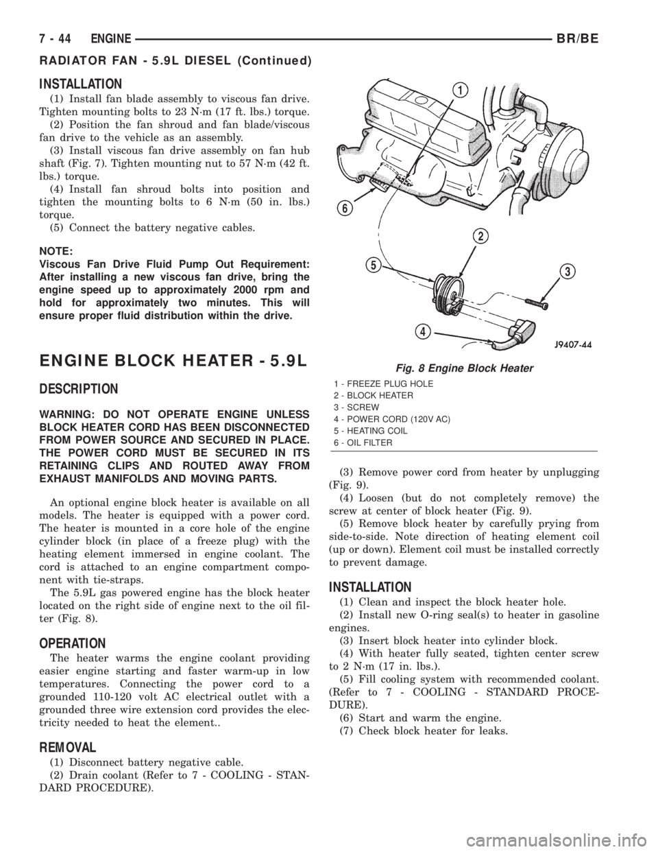
The 5.9L gas powered engine has the block heater
located on the right side of engine next to the oil fil-
ter (Fig. 8).
OPERATION
The heater warms the engine coolant providing
easier engine starting and faster warm-up in low
temperatures. Connecting the power cord to a
grounded 110-120 volt AC electrical outlet with a
grounded three wire extension cord provides the elec-
tricity needed to heat the element..
REMOVAL
(1) Disconnect battery negative cable.
(2) Drain coolant (Refer to 7 - COOLING - STAN-
DARD PROCEDURE).(3) Remove power cord from heater by unplugging
(Fig. 9).
(4) Loosen (but do not completely remove) the
screw at center of block heater (Fig. 9).
(5) Remove block heater by carefully prying from
side-to-side. Note direction of heating element coil
(up or down). Element coil must be installed correctly
to prevent damage.
INSTALLATION
(1) Clean and inspect the block heater hole.
(2) Install new O-ring seal(s) to heater in gasoline
engines.
(3) Insert block heater into cylinder block.
(4) With heater fully seated, tighten center screw
to 2 N´m (17 in. lbs.).
(5) Fill cooling system with recommended coolant.
(Refer to 7 - COOLING - STANDARD PROCE-
DURE).
(6) Start and warm the engine.
(7) Check block heater for leaks.
Fig. 8 Engine Block Heater
1 - FREEZE PLUG HOLE
2 - BLOCK HEATER
3 - SCREW
4 - POWER CORD (120V AC)
5 - HEATING COIL
6 - OIL FILTER
7 - 44 ENGINEBR/BE
RADIATOR FAN - 5.9L DIESEL (Continued)