2002 DODGE RAM remote start
[x] Cancel search: remote startPage 604 of 2255
may be damaged. Service replacement clocksprings
are shipped pre-centered and with the auto-locking
tabs engaged. A piece of tape covers the auto-locking
tabs to discourage tampering. These auto-locking
tabs should not be disengaged until the clockspring
has been installed on the steering column. If this
shipping tape is removed or damaged, or if the auto-
locking tabs are disengaged before the clockspring is
installed on a steering column, the clockspring cen-
tering procedure must be performed. (Refer to 8 -
ELECTRICAL/RESTRAINTS/CLOCKSPRING -
STANDARD PROCEDURE - CLOCKSPRING CEN-
TERING).
STANDARD PROCEDURE - CLOCKSPRING
CENTERING
The clockspring is designed to wind and unwind
when the steering wheel is rotated, but is only
designed to rotate the same number of turns (about
five complete rotations) as the steering wheel can be
turned from stop to stop. Centering the clockspring
indexes the clockspring tape to other steering compo-
nents so that it can operate within its designed
travel limits. The rotor of a centered clockspring can
be rotated two and one-half turns in either direction
from the centered position, without damaging the
clockspring tape.
However, if the clockspring is removed for service
or if the steering column is disconnected from the
steering gear, the clockspring tape can change posi-
tion relative to the other steering components. The
clockspring must then be re-centered following com-
pletion of such service or the clockspring tape may be
damaged. Service replacement clocksprings are
shipped pre-centered and with the auto-locking tabs
engaged (raised). These auto-locking tabs should not
be disengaged until the clockspring has been
installed on the steering column. If the auto-locking
tabs are disengaged before the clockspring is
installed on a steering column, the clockspring cen-
tering procedure must be performed.
WARNING: DISABLE THE AIRBAG SYSTEM
BEFORE ATTEMPTING ANY STEERING WHEEL,
STEERING COLUMN, OR INSTRUMENT PANEL
COMPONENT DIAGNOSIS OR SERVICE. DISCON-
NECT AND ISOLATE THE BATTERY NEGATIVE
(GROUND) CABLE, THEN WAIT TWO MINUTES FOR
THE AIRBAG SYSTEM CAPACITOR TO DISCHARGE
BEFORE PERFORMING FURTHER DIAGNOSIS OR
SERVICE. THIS IS THE ONLY SURE WAY TO DIS-
ABLE THE AIRBAG SYSTEM. FAILURE TO TAKE
THE PROPER PRECAUTIONS COULD RESULT IN
ACCIDENTAL AIRBAG DEPLOYMENT AND POSSI-
BLE PERSONAL INJURY.NOTE: Before starting this procedure, be certain to
turn the steering wheel until the front wheels are in
the straight-ahead position.
(1) Place the front wheels in the straight-ahead
position.
(2) Remove the clockspring from the steering col-
umn. (Refer to 8 - ELECTRICAL/RESTRAINTS/
CLOCKSPRING - REMOVAL).
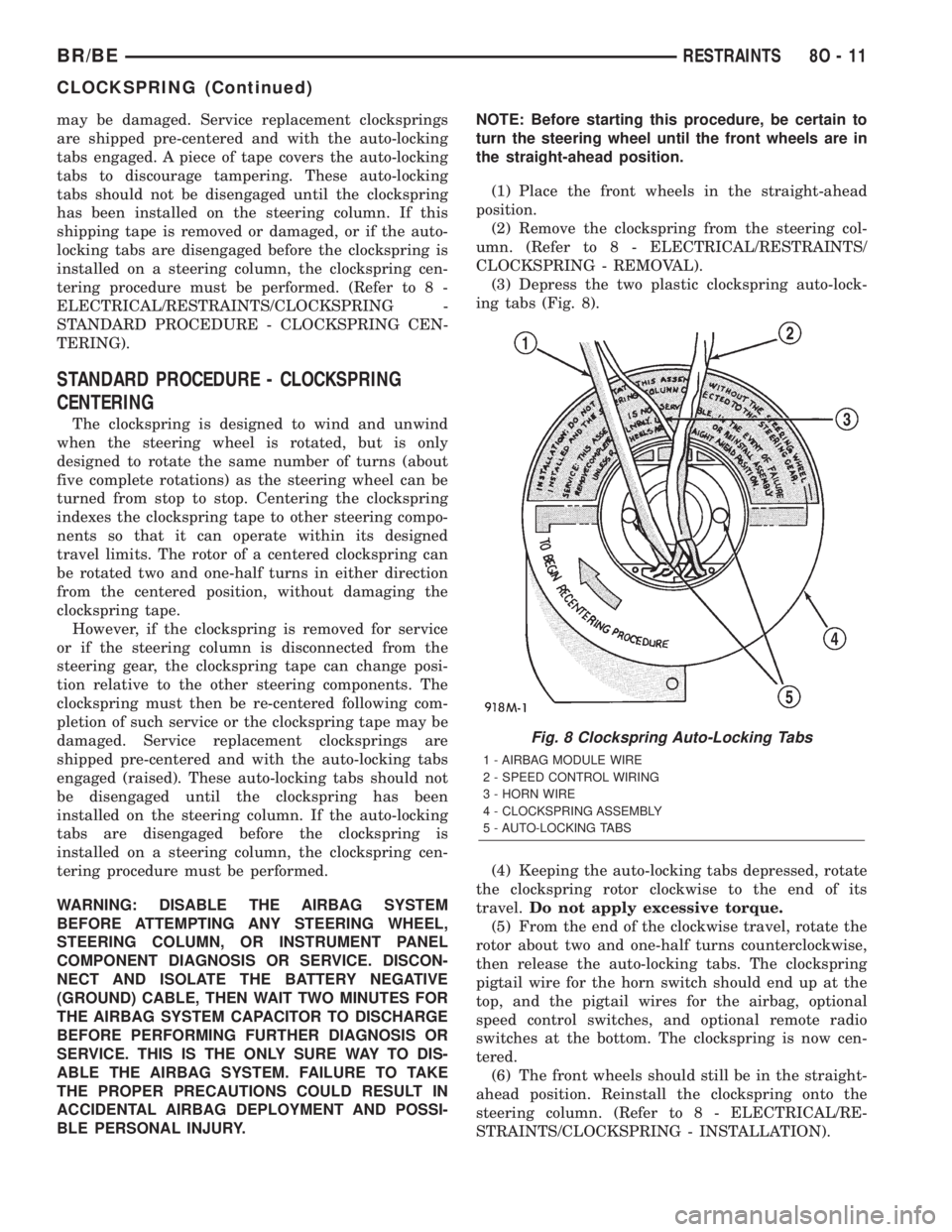
(3) Depress the two plastic clockspring auto-lock-
ing tabs (Fig. 8).
(4) Keeping the auto-locking tabs depressed, rotate
the clockspring rotor clockwise to the end of its
travel.Do not apply excessive torque.
(5) From the end of the clockwise travel, rotate the
rotor about two and one-half turns counterclockwise,
then release the auto-locking tabs. The clockspring
pigtail wire for the horn switch should end up at the
top, and the pigtail wires for the airbag, optional
speed control switches, and optional remote radio
switches at the bottom. The clockspring is now cen-
tered.
(6) The front wheels should still be in the straight-
ahead position. Reinstall the clockspring onto the
steering column. (Refer to 8 - ELECTRICAL/RE-
STRAINTS/CLOCKSPRING - INSTALLATION).
Fig. 8 Clockspring Auto-Locking Tabs
1 - AIRBAG MODULE WIRE
2 - SPEED CONTROL WIRING
3 - HORN WIRE
4 - CLOCKSPRING ASSEMBLY
5 - AUTO-LOCKING TABS
BR/BERESTRAINTS 8O - 11
CLOCKSPRING (Continued)
Page 605 of 2255
REMOVAL
The clockspring cannot be repaired. It must be
replaced if faulty or damaged, or if the driver airbag
has been deployed.
WARNING: DISABLE THE AIRBAG SYSTEM
BEFORE ATTEMPTING ANY STEERING WHEEL,
STEERING COLUMN, OR INSTRUMENT PANEL
COMPONENT DIAGNOSIS OR SERVICE. DISCON-
NECT AND ISOLATE THE BATTERY NEGATIVE
(GROUND) CABLE, THEN WAIT TWO MINUTES FOR
THE AIRBAG SYSTEM CAPACITOR TO DISCHARGE
BEFORE PERFORMING FURTHER DIAGNOSIS OR
SERVICE. THIS IS THE ONLY SURE WAY TO DIS-
ABLE THE AIRBAG SYSTEM. FAILURE TO TAKE
THE PROPER PRECAUTIONS COULD RESULT IN
ACCIDENTAL AIRBAG DEPLOYMENT AND POSSI-
BLE PERSONAL INJURY.
NOTE: Before starting this procedure, be certain to
turn the steering wheel until the front wheels are in
the straight-ahead position.
(1) Place the front wheels in the straight-ahead
position.
(2) Remove the driver airbag from the steering
wheel. (Refer to 8 - ELECTRICAL/RESTRAINTS/
DRIVER AIRBAG - REMOVAL).
(3) If the vehicle is so equipped, disconnect the
clockspring pigtail wire connectors from the speed
control switches and the remote radio switches
located within the hub cavity of the steering wheel.
(4) Remove the nut that secures the steering wheel
armature to the steering column upper shaft, which
is located within the hub cavity of the steering wheel.
(5) Pull the steering wheel off of the steering col-
umn upper shaft spline using a steering wheel puller
(Special Tool C-3428-B).
(6) Remove the steering column opening cover
from the instrument panel. (Refer to 23 - BODY/IN-
STRUMENT PANEL/STEERING COLUMN OPEN-
ING COVER - REMOVAL).
(7) If the vehicle is so equipped, unscrew the lever
from the tilt steering column adjuster mechanism
located on the left side of the column just below the
multi-function switch control stalk. Turn the lever
counterclockwise to unscrew it from the adjuster.
(8) From below the steering column, remove the
two outboard screws that secure the upper shroud to
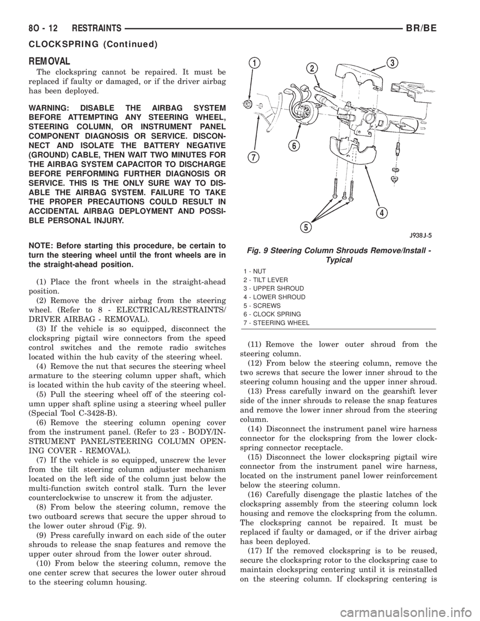
the lower outer shroud (Fig. 9).
(9) Press carefully inward on each side of the outer
shrouds to release the snap features and remove the
upper outer shroud from the lower outer shroud.
(10) From below the steering column, remove the
one center screw that secures the lower outer shroud
to the steering column housing.(11) Remove the lower outer shroud from the
steering column.
(12) From below the steering column, remove the
two screws that secure the lower inner shroud to the
steering column housing and the upper inner shroud.
(13) Press carefully inward on the gearshift lever
side of the inner shrouds to release the snap features
and remove the lower inner shroud from the steering
column.
(14) Disconnect the instrument panel wire harness
connector for the clockspring from the lower clock-
spring connector receptacle.
(15) Disconnect the lower clockspring pigtail wire
connector from the instrument panel wire harness,
located on the instrument panel lower reinforcement
below the steering column.
(16) Carefully disengage the plastic latches of the
clockspring assembly from the steering column lock
housing and remove the clockspring from the column.
The clockspring cannot be repaired. It must be
replaced if faulty or damaged, or if the driver airbag
has been deployed.
(17) If the removed clockspring is to be reused,
secure the clockspring rotor to the clockspring case to
maintain clockspring centering until it is reinstalled
on the steering column. If clockspring centering is
Fig. 9 Steering Column Shrouds Remove/Install -
Typical
1 - NUT
2 - TILT LEVER
3 - UPPER SHROUD
4 - LOWER SHROUD
5 - SCREWS
6 - CLOCK SPRING
7 - STEERING WHEEL
8O - 12 RESTRAINTSBR/BE
CLOCKSPRING (Continued)
Page 606 of 2255
not maintained, the clockspring must be centered
again before it is reinstalled. (Refer to 8 - ELECTRI-
CAL/RESTRAINTS/CLOCKSPRING - STANDARD
PROCEDURE - CLOCKSPRING CENTERING).
INSTALLATION
The clockspring cannot be repaired. It must be
replaced if faulty or damaged, or if the driver airbag
has been deployed.
If the clockspring is not properly centered in rela-
tion to the steering wheel, steering shaft and steer-
ing gear, it may be damaged. (Refer to 8 -
ELECTRICAL/RESTRAINTS/CLOCKSPRING -
STANDARD PROCEDURE - CLOCKSPRING CEN-
TERING). Service replacement clocksprings are
shipped pre-centered and with a piece of tape cover-
ing the engaged clockspring auto-locking tabs. This
tape should not be removed until the clockspring has
been installed on the steering column. If the tape is
removed before the clockspring is installed on a
steering column, the clockspring centering procedure
must be performed.
WARNING: DISABLE THE AIRBAG SYSTEM
BEFORE ATTEMPTING ANY STEERING WHEEL,
STEERING COLUMN, OR INSTRUMENT PANEL
COMPONENT DIAGNOSIS OR SERVICE. DISCON-
NECT AND ISOLATE THE BATTERY NEGATIVE
(GROUND) CABLE, THEN WAIT TWO MINUTES FOR
THE AIRBAG SYSTEM CAPACITOR TO DISCHARGE
BEFORE PERFORMING FURTHER DIAGNOSIS OR
SERVICE. THIS IS THE ONLY SURE WAY TO DIS-
ABLE THE AIRBAG SYSTEM. FAILURE TO TAKE
THE PROPER PRECAUTIONS COULD RESULT IN
ACCIDENTAL AIRBAG DEPLOYMENT AND POSSI-
BLE PERSONAL INJURY.
NOTE: Before starting this procedure, be certain
that the front wheels are still in the straight-ahead
position.
(1) Carefully slide the centered clockspring down
over the steering column upper shaft until the clock-
spring latches engage the steering column lock hous-
ing (Fig. 9).
(2) Reconnect the lower clockspring pigtail wire
connector to the instrument panel wire harness con-
nector located near the instrument panel lower rein-
forcement, below the steering column. Be certain that
the pigtail wire locator clips are properly seated on
the outside of the wiring trough and that the connec-
tor latches are fully engaged.
(3) Reconnect the instrument panel wire harness
connector for the clockspring to the lower clockspring
connector receptacle.(4) Position the lower inner shroud onto the steer-
ing column. Be certain to insert the gearshift lever
hider strip into the channel located on the inside sur-
face of the shroud.
(5) Align the locking tabs on the gearshift lever
side of the upper inner shroud with the receptacles
on the lower inner shroud and apply hand pressure
to snap them together.
(6) From below the steering column, install and
tighten the two screws that secure the lower inner
shroud to the steering column housing and the upper
inner shroud. Tighten the screws to 2 N´m (18 in.
lbs.).
(7) Position the lower outer shroud onto the steer-
ing column. Be certain that the lower clockspring
pigtail wire is routed inside the shrouds.
(8) From below the steering column, install and
tighten the one center screw that secures the lower
outer shroud to the steering column housing. Tighten
the screw to 2 N´m (18 in. lbs.).
(9) Align the locking tabs on the upper outer
shroud with the receptacles on the lower outer
shroud and apply hand pressure to snap them
together.
(10) From below the steering column, install and
tighten the two outboard screws that secure the
lower outer shroud to the upper outer shroud.
Tighten the screws to 2 N´m (18 in. lbs.).
(11) If the vehicle is so equipped, reinstall the
lever into the tilt steering column adjuster on the left
side of the column. Turn the lever clockwise to screw
it into the adjuster.
(12) Reinstall the steering column opening cover
onto the instrument panel. (Refer to 23 - BODY/IN-
STRUMENT PANEL/STEERING COLUMN OPEN-
ING COVER - INSTALLATION).
(13) Reinstall the steering wheel onto the steering
column upper shaft. Be certain to index the flats on
the hub of the steering wheel with the formations on
the inside of the clockspring hub. Pull the upper
clockspring pigtail wires through the upper and
lower holes between the steering wheel back trim
cover and the steering wheel armature.
(14) Install and tighten the steering wheel mount-
ing nut. Tighten the nut to 61 N´m (45 ft. lbs.). Be
certain not to pinch the pigtail wires between the
steering wheel and the nut.
(15) If the vehicle is so equipped, reconnect the
upper clockspring pigtail wire connectors to the
speed control switches and/or the remote radio
switches. Be certain that the upper clockspring pig-
tail wires are routed between the steering wheel back
trim cover and the steering wheel armature.
(16) Reinstall the driver airbag onto the steering
wheel. (Refer to 8 - ELECTRICAL/RESTRAINTS/
DRIVER AIRBAG - INSTALLATION).
BR/BERESTRAINTS 8O - 13
CLOCKSPRING (Continued)
Page 641 of 2255
Hard wired circuitry connects many of the VTSS
components to each other through the electrical sys-
tem of the vehicle. These hard wired circuits are
integral to several wire harnesses, which are routed
throughout the vehicle and retained by many differ-
ent methods. These circuits may be connected to each
other, to the vehicle electrical system and to the
VTSS components through the use of a combination
of soldered splices, splice block connectors, and many
different types of wire harness terminal connectors
and insulators. Refer to the appropriate wiring infor-
mation. The wiring information includes wiring dia-
grams, proper wire and connector repair procedures,
further details on wire harness routing and reten-
tion, as well as pin-out and location views for the
various wire harness connectors, splices and grounds.
OPERATION
A Central Timer Module (CTM) is used on this
model to control and integrate many of the electronic
functions and features included in the Vehicle Theft
Security System (VTSS). In the VTSS, the CTM
receives inputs indicating the status of the door ajar
switches, the door cylinder lock switch, and the igni-
tion switch. The programming in the CTM allows it
to process the information from all of these inputs
and send control outputs to energize or de-energize
the horn relay, the headlamp relay, and the VTSS
indicator. The control of these inputs and outputs are
what constitute all of the features of the VTSS. Fol-
lowing is information on the operation of each of the
VTSS features. Refer to the owner's manual in the
vehicle glove box for more information on the fea-
tures, use and operation of the VTSS.
ENABLING
The high-line or premium version of the CTM must
have the VTSS function electronically enabled in
order for the VTSS to perform as designed. The logic
in the CTM keeps its VTSS function dormant until it
is enabled using a DRBIIItscan tool. The VTSS
function of the high-line or premium CTM is enabled
on vehicles equipped with the VTSS option at the
factory, but a service replacement CTM must be
VTSS-enabled by the dealer using a DRBIIItscan
tool. Refer to the appropriate diagnostic information.
The VTSS engine no-run feature is disabled when
it is shipped from the factory. This is done by pro-
gramming within the Powertrain Control Module
(PCM). The logic in the PCM prevents the VTSS
engine no-run feature from arming until the engine
start counter within the PCM sees twenty enginestarts. The VTSS no-run feature must be enabled by
the dealer when the vehicle is received from the
assembly plant. Once the VTSS engine no-run fea-
ture has been enabled, it cannot be disabled unless
the PCM is replaced with a new unit. The same
VTSS engine no-run feature enable logic will apply
anytime the PCM is replaced with a new unit.
ARMING
Passive arming of the VTSS occurs when the vehi-
cle is exited with the key removed from the ignition
switch, the headlamps are turned off, and the doors
are locked while they are open using the power lock
switch, or locked after they are closed by turning
either front door lock cylinder to the lock position
using the key. The power lock switch will not func-
tion if the key is in the ignition switch or the head-
lamps are turned on with the driver side front door
open. The VTSS will not arm if the doors are locked
using the mechanical lock button. Active arming of
the VTSS occurs when the ªLockº button on the
Remote Keyless Entry (RKE) transmitter is
depressed to lock the vehicle. For active arming to
occur, the doors must be closed and the ignition
switch must be in the Off position when the RKE
transmitter ªLockº button is depressed. However,
once the VTSS arming process has been completed,
the ignition switch can be turned to the Accessory
position without triggering the alarm.
Once the VTSS begins passive or active arming,
the security indicator lamp in the overhead console
will flash rapidly for about fifteen seconds. This indi-
cates that the VTSS arming is in progress. Turning a
key in the ignition switch, opening a door, or unlock-
ing a door by any means during the fifteen second
arming process will cause the VTSS indicator to stop
flashing and the arming process to abort. Once the
fifteen second arming function is successfully com-
pleted, the indicator will flash at a slower rate, indi-
cating that the VTSS is armed.
DISARMING
Passive disarming of the VTSS occurs when the
vehicle is unlocked using the key to unlock either
front door. Active disarming of the VTSS occurs when
the vehicle is unlocked by depressing the ªUnlockº
button of the RKE transmitter. Once the alarm has
been activated (horn pulsing, headlamps flashing,
and the engine no-run feature), either disarming
method will also deactivate the alarm. Depressing
the ªPanicº button on the RKE transmitter willnot
disarm the VTSS.
8Q - 2 VEHICLE THEFT SECURITYBR/BE
VEHICLE THEFT SECURITY (Continued)
Page 730 of 2255
8W-15 GROUND DISTRIBUTION
Component Page
A/C Compressor Clutch.................8W-15-8, 10
A/C Heater Temperature Select.............8W-15-12
A/C-Heater Control.....................8W-15-14
Aftermarket Trailer Tow Connector............8W-15-6
Airbag Control Module....................8W-15-5
Ash Receiver Lamp.....................8W-15-14
Automatic Day/Night Mirror...............8W-15-13
Auxiliary Battery.......................8W-15-11
Battery.............................8W-15-11
Blend Door Actuator.....................8W-15-12
Blower Motor Relay......................8W-15-2
Brake Lamp Switch.....................8W-15-12
Brake Pressure Switch....................8W-15-3
Center High Mounted Stop Lamp No. 1........8W-15-17
Center High Mounted Stop Lamp No. 2........8W-15-17
Center Identification Lamp................8W-15-18
Central Timer Module.................8W-15-12, 13
Cigar Lighter.........................8W-15-14
Clockspring...........................8W-15-4
Combination Flasher....................8W-15-13
Controller Antilock Brake..................8W-15-5
Cummins Bus.........................8W-15-10
Cup Holder Lamp......................8W-15-14
Data Link Connector................8W-15-8, 10, 12
Daytime Running Lamp Module............8W-15-2, 3
Driver Cylinder Lock Switch...............8W-15-16
Driver Door Ajar Switch..................8W-15-16
Driver Door Window/Lock Switch..........8W-15-16, 17
Driver Heated Seat Cushion...............8W-15-15
Driver Heated Seat Switch................8W-15-13
Driver Power Seat Switch..............8W-15-15, 17
Electric Brake Provision..................8W-15-14
Engine Control Module....................8W-15-9
Engine Starter Motor Relay...............8W-15-8, 9
Fuel Heater..........................8W-15-10
Fuel Heater Relay.......................8W-15-2
Fuel Injection Pump.....................8W-15-9
Fuel Pump Module......................8W-15-7
Fuel Pump Relay.......................8W-15-2
Fuel Transfer Pump.....................8W-15-10
G100......................8W-15-2, 3, 4, 5, 7, 12
G101...............................8W-15-5
G102...............................8W-15-2
G105...............................8W-15-8
G107...............................8W-15-10
G113...............................8W-15-11
G114...............................8W-15-11
G115...............................8W-15-11
G116...............................8W-15-11
G117...............................8W-15-11
G118...............................8W-15-11
G120...............................8W-15-11
G200...........................8W-15-7, 12, 14
G201..........................8W-15-12, 13, 14
G300..........................8W-15-15, 16, 17
G301...............................8W-15-17
G302...............................8W-15-18
Glove Box Lamp And Switch...............8W-15-14
Headlamp Beam Select Switch..............8W-15-14
Headlamp Switch....................8W-15-13, 14
Heated Mirror Switch....................8W-15-13
High Note Horn........................8W-15-7
Ignition Switch........................8W-15-13
Instrument Cluster...................8W-15-12, 14
Component Page
Intake Air Heater Relay No. 1...............8W-15-9
Intake Air Heater Relay No. 2...............8W-15-9
Joint Connector No. 1...................8W-15-2, 5
Joint Connector No. 2....................8W-15-9
Joint Connector No. 5.................8W-15-13, 14
Joint Connector No. 6...................8W-15-4, 5
Joint Connector No. 8..................8W-15-5, 13
Junction Block...................8W-15-12, 13, 14
Left Back-Up Lamp......................8W-15-6
Left Front Door Speaker...................8W-15-4
Left Front Fender Lamp...................8W-15-6
Left License Lamp.......................8W-15-6
Left Outboard Clearance Lamp.............8W-15-18
Left Outboard Identification Lamp...........8W-15-18
Left Park/Turn Signal Lamp................8W-15-3
Left Power Mirror......................8W-15-16
Left Rear Fender Lamp...................8W-15-6
Left Remote Radio Switch..................8W-15-4
Left Tail/Stop/Turn Signal Lamp.............8W-15-6
Left Visor/Vanity Lamp...................8W-15-13
Low Note Horn.........................8W-15-7
Overdrive Switch.......................8W-15-12
Overhead Console......................8W-15-12
Oxygen Sensor 1/2 Left Bank Down...........8W-15-8
Oxygen Sensor 1/2 Pre-Catalyst..............8W-15-8
Oxygen Sensor 1/3 Post-Catalyst.............8W-15-8
Oxygen Sensor 2/2 Right Bank Down..........8W-15-8
Passenger Airbag On/Off Switch..............8W-15-5
Passenger Cylinder Lock Switch.............8W-15-16
Passenger Door Ajar Switch................8W-15-16
Passenger Door Window/Lock Switch..........8W-15-16
Passenger Heated Seat Cushion.............8W-15-15
Passenger Heated Seat Switch..............8W-15-13
Passenger Power Seat Switch..............8W-15-15
Power Distribution Center.................8W-15-2
Power Mirror Switch....................8W-15-16
Power Outlet.........................8W-15-14
Powertrain Control Module..............8W-15-8, 10
Quad High Beam Relay...................8W-15-2
Radio...............................8W-15-5
Radio Choke Relay......................8W-15-4
Right Back-Up Lamp.....................8W-15-6
Right Front Door Speaker..................8W-15-4
Right Front Fender Lamp..................8W-15-6
Right License Lamp......................8W-15-6
Right Outboard Clearance Lamp............8W-15-18
Right Outboard Identification Lamp..........8W-15-18
Right Park/Turn Signal Lamp...............8W-15-7
Right Power Mirror.....................8W-15-16
Right Rear Fender Lamp..................8W-15-6
Right Remote Radio Switch.................8W-15-4
Right Tail/Stop/Turn Signal Lamp............8W-15-6
Right Visor/Vanity Lamp..................8W-15-13
Seat Belt Switch.....................8W-15-15, 17
Seat Heat Interface Module................8W-15-15
Security Relay.........................8W-15-2
Speed Control Servo.....................8W-15-3
Tailgate Lamp.........................8W-15-6
Trailer Tow Connector....................8W-15-6
Trailer Tow Relay.......................8W-15-2
Underhood Lamp.......................8W-15-3
Washer Fluid Level Switch.................8W-15-3
Windshield Washer Pump..................8W-15-7
Wiper Motor...........................8W-15-7
BR/BE8W-15 GROUND DISTRIBUTION 8W - 15 - 1
Page 969 of 2255

CENTRAL TIMER MODULE C2 - 18 WAY
CAV CIRCUIT FUNCTION
1 P33 22OR/BK DOOR LOCK DRIVER
2 M11 22PK/LB COURTESY LAMP SWITCH OUTPUT
3 Z3 18BK/OR GROUND
4 P30 22OR/DG PASSENGER DOOR LOCK SWITCH OUTPUT
5 F12 22DB/WT FUSED IGNITION SWITCH OUTPUT (RUN-START)
6 G50 22RD/DB SECURITY RELAY CONTROL
7 P132 16OR/BK HEATED SEAT RELAY CONTROL
8 G69 22BK VTSS INDICATOR DRIVER
9 P34 22PK/BK DOOR UNLOCK DRIVER
10 G73 22LG/OR CYLINDER LOCK SWITCH MUX
11 M22 22WT DOME LAMP SWITCH SENSE
12 - -
13 P31 22PK/DG PASSENGER DOOR UNLOCK SWITCH OUTPUT
14 X20 22RD/BK RADIO CONTROL MUX
15 - -
16 D1 20VT/BR CCD BUS (+)
17 D2 20WT/BK CCD BUS (-)
18 X3 20BK/RD HORN RELAY CONTROL
CIGAR LIGHTER - NATURAL 3 WAY
CAV CIRCUIT FUNCTION
1 F30 18RD/OR FUSED IGNITION SWITCH OUTPUT (RUN-ACC)
2- -
3 Z3 18BK/OR GROUND
CLOCKSPRING C1-5WAY
CAV CIRCUIT FUNCTION
1 V37 22RD/LG SPEED CONTROL SWITCH SIGNAL
2 Z9 20BK/VT (HIGHLINE (REMOTE
RADIO))GROUND
3 K4 22BK/LB SENSOR GROUND
4 X20 22RD/BK (EXCEPT BASE)) RADIO CONTROL MUX
5 X3 20BK/RD HORN RELAY CONTROL
CLOCKSPRING C2 - YELLOW 2 WAY
CAV CIRCUIT FUNCTION
1 R43 18BK/LB DRIVER AIRBAG LINE 2
2 R45 18DG/LB DRIVER AIRBAG LINE 1
8W - 80 - 34 8W-80 CONNECTOR PIN-OUTSBR/BE
Page 988 of 2255
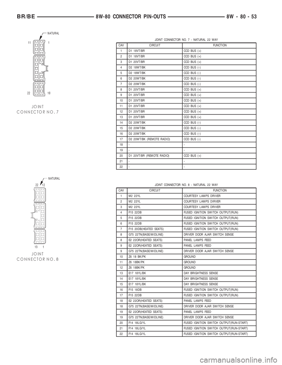
JOINT CONNECTOR NO.7-NATURAL 22 WAY
CAV CIRCUIT FUNCTION
1 D1 18VT/BR CCD BUS (+)
2 D1 18VT/BR CCD BUS (+)
3 D1 20VT/BR CCD BUS (+)
4 D2 18WT/BK CCD BUS (-)
5 D2 18WT/BK CCD BUS (-)
6 D2 20WT/BK CCD BUS (-)
7 D2 20WT/BK CCD BUS (-)
8 D1 20VT/BR CCD BUS (+)
9 D1 20VT/BR CCD BUS (+)
10 D1 20VT/BR CCD BUS (+)
11 D1 20VT/BR CCD BUS (+)
12 D1 20VT/BR CCD BUS (+)
13 D1 20VT/BR CCD BUS (+)
14 D2 20WT/BK CCD BUS (-)
15 D2 20WT/BK CCD BUS (-)
16 D2 20WT/BK CCD BUS (-)
17 D2 20WT/BK (REMOTE RADIO) CCD BUS (-)
18 - -
19 - -
20 D1 20VT/BR (REMOTE RADIO) CCD BUS (+)
21 - -
22 - -
JOINT CONNECTOR NO.8-NATURAL 22 WAY
CAV CIRCUIT FUNCTION
1 M2 22YL COURTESY LAMPS DRIVER
2 M2 22YL COURTESY LAMPS DIRVER
3 M2 22YL COURTESY LAMPS DRIVER
4 F15 22DB FUSED IGNITION SWITCH OUTPUT(RUN)
5 F15 22DB FUSED IGNITION SWITCH OUTPUT(RUN)
6 F15 22DB FUSED IGNITION SWITCH OUTPUT(RUN)
7 F15 20DB(HEATED SEATS) FUSED IGNITION SWITCH OUTPUT(RUN)
8 G75 22TN(BASE/MIDLINE) DRIVER DOOR AJAR SWITCH SENSE
8 E2 22OR(HEATED SEATS) PANEL LAMPS FEED
9 E2 22OR(HEATED SEATS) PANEL LAMPS FEED
9 G75 22TN(BASE/MIDLINE) DRIVER DOOR AJAR SWITCH SENSE
10 Z6 18 BK/PK GROUND
11 Z6 18BK/PK GROUND
12 Z6 18BK/PK GROUND
13 E17 18YL/BK DAY BRIGHTNESS SENSE
14 E17 18YL/BK DAY BRIGHTNESS SENSE
15 E17 18YL/BK DAY BRIGHTNESS SENSE
16 F15 18DB FUSED IGNITION SWITCH OUTPUT(RUN)
17 F15 22DB FUSED IGNITION SWITCH OUTPUT(RUN)
18 E2 22OR(HEATED SEATS) PANEL LAMPS FEED
18 G75 22TN(BASE/MIDLINE) DRIVER DOOR AJAR SWITCH SENSE
19 E2 22OR(HEATED SEATS) PANEL LAMPS FEED
19 G75 22TN(BASE/MIDLINE) DRIVER DOOR AJAR SWITCH SENSE
20 F14 18LG/YL FUSED IGNITION SWITCH OUTPUT(RUN-START)
21 F14 18LG/YL FUSED IGNITION SWITCH OUTPUT(RUN-START)
22 F14 18LG/YL FUSED IGNITION SWITCH OUTPUT(RUN-START)
BR/BE8W-80 CONNECTOR PIN-OUTS 8W - 80 - 53
Page 1356 of 2255
DIAGNOSIS AND TESTING
DIAGNOSIS AND TESTING - FUEL SYSTEM AIR
LEAK VACUUM TEST
The proceeding test will determine if a fuel system
air leak exists at the engine. Air leaks will cause
hard starting and/or poor performance.
A hand-operated vacuum pump/gauge equipped
with a remote or built-on fluid container will be used.
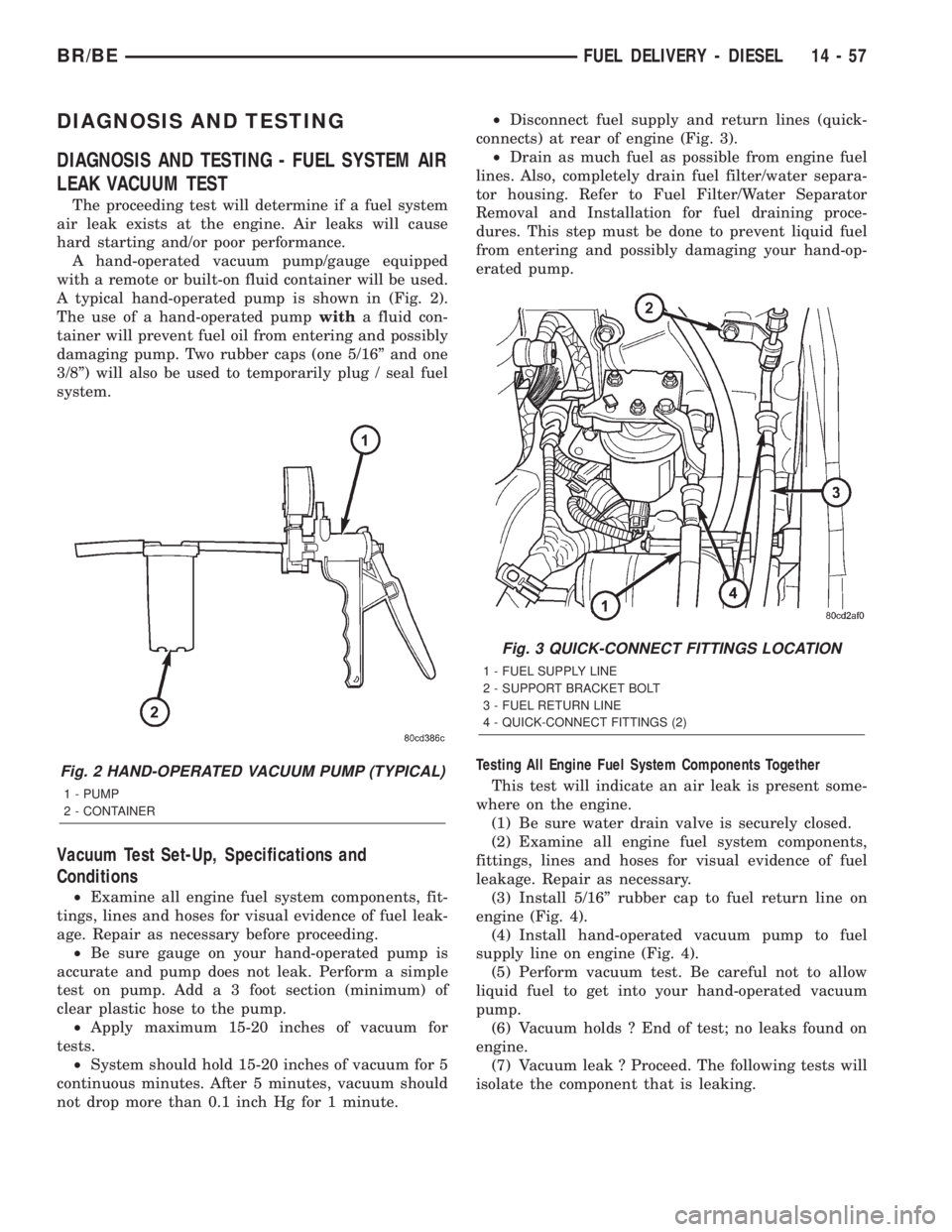
A typical hand-operated pump is shown in (Fig. 2).
The use of a hand-operated pumpwitha fluid con-
tainer will prevent fuel oil from entering and possibly
damaging pump. Two rubber caps (one 5/16º and one
3/8º) will also be used to temporarily plug / seal fuel
system.
Vacuum Test Set-Up, Specifications and
Conditions
²Examine all engine fuel system components, fit-
tings, lines and hoses for visual evidence of fuel leak-
age. Repair as necessary before proceeding.
²Be sure gauge on your hand-operated pump is
accurate and pump does not leak. Perform a simple
test on pump. Add a 3 foot section (minimum) of
clear plastic hose to the pump.
²Apply maximum 15-20 inches of vacuum for
tests.
²System should hold 15-20 inches of vacuum for 5
continuous minutes. After 5 minutes, vacuum should
not drop more than 0.1 inch Hg for 1 minute.²Disconnect fuel supply and return lines (quick-
connects) at rear of engine (Fig. 3).
²Drain as much fuel as possible from engine fuel
lines. Also, completely drain fuel filter/water separa-
tor housing. Refer to Fuel Filter/Water Separator
Removal and Installation for fuel draining proce-
dures. This step must be done to prevent liquid fuel
from entering and possibly damaging your hand-op-
erated pump.
Testing All Engine Fuel System Components Together
This test will indicate an air leak is present some-
where on the engine.
(1) Be sure water drain valve is securely closed.
(2) Examine all engine fuel system components,
fittings, lines and hoses for visual evidence of fuel
leakage. Repair as necessary.
(3) Install 5/16º rubber cap to fuel return line on
engine (Fig. 4).
(4) Install hand-operated vacuum pump to fuel
supply line on engine (Fig. 4).
(5) Perform vacuum test. Be careful not to allow
liquid fuel to get into your hand-operated vacuum
pump.
(6) Vacuum holds ? End of test; no leaks found on
engine.
(7) Vacuum leak ? Proceed. The following tests will
isolate the component that is leaking.
Fig. 2 HAND-OPERATED VACUUM PUMP (TYPICAL)
1 - PUMP
2 - CONTAINER
Fig. 3 QUICK-CONNECT FITTINGS LOCATION
1 - FUEL SUPPLY LINE
2 - SUPPORT BRACKET BOLT
3 - FUEL RETURN LINE
4 - QUICK-CONNECT FITTINGS (2)
BR/BEFUEL DELIVERY - DIESEL 14 - 57