2002 DODGE RAM warning
[x] Cancel search: warningPage 2080 of 2255
(2) Install and tighten the three screws that secure
the trim to the instrument panel glove box opening
upper reinforcement. Tighten the mounting screws to
2 N´m (20 in. lbs.).
(3) Close the glove box.
(4) Reconnect the battery negative cable.
INSTRUMENT PANEL TOP
COVER
REMOVAL
WARNING: ON VEHICLES EQUIPPED WITH AIR-
BAGS, DISABLE THE AIRBAG SYSTEM BEFORE
ATTEMPTING ANY STEERING WHEEL, STEERING
COLUMN, SEAT BELT TENSIONER, OR INSTRU-
MENT PANEL COMPONENT DIAGNOSIS OR SER-
VICE. DISCONNECT AND ISOLATE THE BATTERY
NEGATIVE (GROUND) CABLE, THEN WAIT TWO
MINUTES FOR THE AIRBAG SYSTEM CAPACITOR
TO DISCHARGE BEFORE PERFORMING FURTHER
DIAGNOSIS OR SERVICE. THIS IS THE ONLY SURE
WAY TO DISABLE THE AIRBAG SYSTEM. FAILURE
TO TAKE THE PROPER PRECAUTIONS COULD
RESULT IN ACCIDENTAL AIRBAG DEPLOYMENT
AND POSSIBLE PERSONAL INJURY.
(1) Disconnect and isolate the battery negative
cable.
(2) Remove the cluster bezel from the instrument
panel. (Refer to 23 - BODY/INSTRUMENT PANEL/
CLUSTER BEZEL - REMOVAL).
(3) Remove the passenger airbag from the instru-
ment panel. (Refer to 8 - ELECTRICAL/RE-
STRAINTS/PASSENGER AIRBAG - REMOVAL).
(4) Remove the instrument panel from the vehicle.
(Refer to 23 - BODY/INSTRUMENT PANEL -
REMOVAL).
(5) Place the instrument panel on a suitable work
surface. Be certain to take the proper precautions to
protect the instrument panel from any possible cos-
metic damage.
(6) Remove the screws around the perimeter of the
top cover that secure it to the instrument panel
structural support, the defroster duct, and the demis-
ter ducts.
(7) Lift the top cover off of the instrument panel.
INSTALLATION
WARNING: ON VEHICLES EQUIPPED WITH AIR-
BAGS, DISABLE THE AIRBAG SYSTEM BEFORE
ATTEMPTING ANY STEERING WHEEL, STEERING
COLUMN, SEAT BELT TENSIONER, OR INSTRU-
MENT PANEL COMPONENT DIAGNOSIS OR SER-VICE. DISCONNECT AND ISOLATE THE BATTERY
NEGATIVE (GROUND) CABLE, THEN WAIT TWO
MINUTES FOR THE AIRBAG SYSTEM CAPACITOR
TO DISCHARGE BEFORE PERFORMING FURTHER
DIAGNOSIS OR SERVICE. THIS IS THE ONLY SURE
WAY TO DISABLE THE AIRBAG SYSTEM. FAILURE
TO TAKE THE PROPER PRECAUTIONS COULD
RESULT IN ACCIDENTAL AIRBAG DEPLOYMENT
AND POSSIBLE PERSONAL INJURY.
(1) Position the top cover onto the instrument
panel.
(2) Install and tighten the screws around the
perimeter of the top cover that secure it to the
instrument panel structural support, the defroster
duct, and the demister ducts. Tighten the screws to 2
N´m (20 in. lbs.).
(3) Reinstall the instrument panel into the vehicle.
(Refer to 23 - BODY/INSTRUMENT PANEL -
INSTALLATION).
(4) Reinstall the passenger airbag into the instru-
ment panel. (Refer to 8 - ELECTRICAL/RE-
STRAINTS/PASSENGER AIRBAG -
INSTALLATION).
(5) Reinstall the cluster bezel onto the instrument
panel.(Refer to 23 - BODY/INSTRUMENT PANEL/
CLUSTER BEZEL - INSTALLATION).
(6) Reconnect the battery negative cable.
STEERING COLUMN OPENING
COVER
REMOVAL
WARNING: ON VEHICLES EQUIPPED WITH AIR-
BAGS, DISABLE THE AIRBAG SYSTEM BEFORE
ATTEMPTING ANY STEERING WHEEL, STEERING
COLUMN, SEAT BELT TENSIONER, OR INSTRU-
MENT PANEL COMPONENT DIAGNOSIS OR SER-
VICE. DISCONNECT AND ISOLATE THE BATTERY
NEGATIVE (GROUND) CABLE, THEN WAIT TWO
MINUTES FOR THE AIRBAG SYSTEM CAPACITOR
TO DISCHARGE BEFORE PERFORMING FURTHER
DIAGNOSIS OR SERVICE. THIS IS THE ONLY SURE
WAY TO DISABLE THE AIRBAG SYSTEM. FAILURE
TO TAKE THE PROPER PRECAUTIONS COULD
RESULT IN ACCIDENTAL AIRBAG DEPLOYMENT
AND POSSIBLE PERSONAL INJURY.
(1) Disconnect and isolate the battery negative
cable.
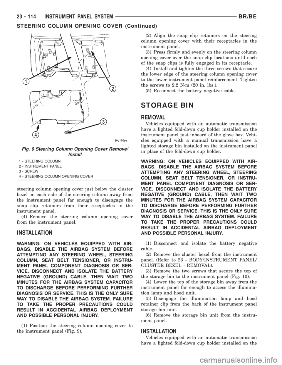
(2) Remove the three screws that secure the lower
edge of the steering column opening cover to the
lower instrument panel reinforcement (Fig. 9).
(3) Using a trim stick or another suitable wide
flat-bladed tool, gently pry the upper edge of the
BR/BEINSTRUMENT PANEL SYSTEM 23 - 113
GLOVE BOX OPENING UPPER TRIM (Continued)
Page 2081 of 2255
steering column opening cover just below the cluster
bezel on each side of the steering column away from
the instrument panel far enough to disengage the
snap clip retainers from their receptacles in the
instrument panel.
(4) Remove the steering column opening cover
from the instrument panel.
INSTALLATION
WARNING: ON VEHICLES EQUIPPED WITH AIR-
BAGS, DISABLE THE AIRBAG SYSTEM BEFORE
ATTEMPTING ANY STEERING WHEEL, STEERING
COLUMN, SEAT BELT TENSIONER, OR INSTRU-
MENT PANEL COMPONENT DIAGNOSIS OR SER-
VICE. DISCONNECT AND ISOLATE THE BATTERY
NEGATIVE (GROUND) CABLE, THEN WAIT TWO
MINUTES FOR THE AIRBAG SYSTEM CAPACITOR
TO DISCHARGE BEFORE PERFORMING FURTHER
DIAGNOSIS OR SERVICE. THIS IS THE ONLY SURE
WAY TO DISABLE THE AIRBAG SYSTEM. FAILURE
TO TAKE THE PROPER PRECAUTIONS COULD
RESULT IN ACCIDENTAL AIRBAG DEPLOYMENT
AND POSSIBLE PERSONAL INJURY.
(1) Position the steering column opening cover to
the instrument panel (Fig. 9).(2) Align the snap clip retainers on the steering
column opening cover with their receptacles in the
instrument panel.
(3) Press firmly and evenly on the steering column
opening cover over the snap clip locations until each
of the snap clips is fully engaged in its receptacle.
(4) Install and tighten the three screws that secure
the lower edge of the steering column opening cover
to the lower instrument panel reinforcement. Tighten
the screws to 2.2 N´m (20 in. lbs.).
(5) Reconnect the battery negative cable.
STORAGE BIN
REMOVAL
Vehicles equipped with an automatic transmission
have a lighted fold-down cup holder installed on the
instrument panel just inboard of the glove box. Vehi-
cles equipped with a manual transmission have a
lighted storage bin installed on the instrument panel
in place of the fold-down cup holder.
WARNING: ON VEHICLES EQUIPPED WITH AIR-
BAGS, DISABLE THE AIRBAG SYSTEM BEFORE
ATTEMPTING ANY STEERING WHEEL, STEERING
COLUMN, SEAT BELT TENSIONER, OR INSTRU-
MENT PANEL COMPONENT DIAGNOSIS OR SER-
VICE. DISCONNECT AND ISOLATE THE BATTERY
NEGATIVE (GROUND) CABLE, THEN WAIT TWO
MINUTES FOR THE AIRBAG SYSTEM CAPACITOR
TO DISCHARGE BEFORE PERFORMING FURTHER
DIAGNOSIS OR SERVICE. THIS IS THE ONLY SURE
WAY TO DISABLE THE AIRBAG SYSTEM. FAILURE
TO TAKE THE PROPER PRECAUTIONS COULD
RESULT IN ACCIDENTAL AIRBAG DEPLOYMENT
AND POSSIBLE PERSONAL INJURY.
(1) Disconnect and isolate the battery negative
cable.
(2) Remove the cluster bezel from the instrument
panel. (Refer to 23 - BODY/INSTRUMENT PANEL/
CLUSTER BEZEL - REMOVAL).
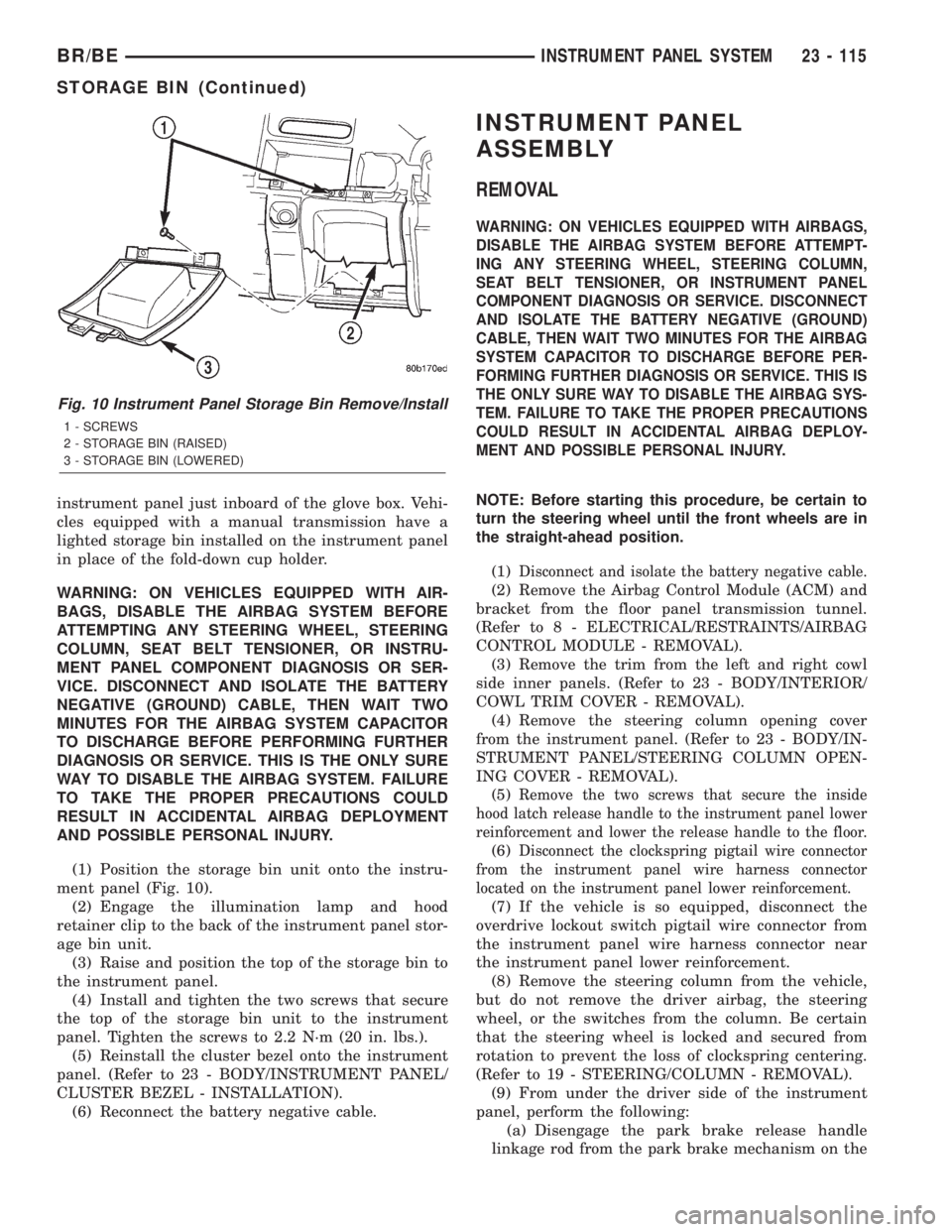
(3) Remove the two screws that secure the top of
the storage bin to the instrument panel (Fig. 10).
(4) Lower the top of the storage bin away from the
instrument panel far enough to access the illumina-
tion lamp and hood unit.
(5) Disengage the illumination lamp and hood
retainer clip from the back of the instrument panel
storage bin unit.
(6) Remove the storage bin unit from the instru-
ment panel.
INSTALLATION
Vehicles equipped with an automatic transmission
have a lighted fold-down cup holder installed on the
Fig. 9 Steering Column Opening Cover Remove/
Install
1 - STEERING COLUMN
2 - INSTRUMENT PANEL
3 - SCREW
4 - STEERING COLUMN OPENING COVER
23 - 114 INSTRUMENT PANEL SYSTEMBR/BE
STEERING COLUMN OPENING COVER (Continued)
Page 2082 of 2255
instrument panel just inboard of the glove box. Vehi-
cles equipped with a manual transmission have a
lighted storage bin installed on the instrument panel
in place of the fold-down cup holder.
WARNING: ON VEHICLES EQUIPPED WITH AIR-
BAGS, DISABLE THE AIRBAG SYSTEM BEFORE
ATTEMPTING ANY STEERING WHEEL, STEERING
COLUMN, SEAT BELT TENSIONER, OR INSTRU-
MENT PANEL COMPONENT DIAGNOSIS OR SER-
VICE. DISCONNECT AND ISOLATE THE BATTERY
NEGATIVE (GROUND) CABLE, THEN WAIT TWO
MINUTES FOR THE AIRBAG SYSTEM CAPACITOR
TO DISCHARGE BEFORE PERFORMING FURTHER
DIAGNOSIS OR SERVICE. THIS IS THE ONLY SURE
WAY TO DISABLE THE AIRBAG SYSTEM. FAILURE
TO TAKE THE PROPER PRECAUTIONS COULD
RESULT IN ACCIDENTAL AIRBAG DEPLOYMENT
AND POSSIBLE PERSONAL INJURY.
(1) Position the storage bin unit onto the instru-
ment panel (Fig. 10).
(2) Engage the illumination lamp and hood
retainer clip to the back of the instrument panel stor-
age bin unit.
(3) Raise and position the top of the storage bin to
the instrument panel.
(4) Install and tighten the two screws that secure
the top of the storage bin unit to the instrument
panel. Tighten the screws to 2.2 N´m (20 in. lbs.).
(5) Reinstall the cluster bezel onto the instrument
panel. (Refer to 23 - BODY/INSTRUMENT PANEL/
CLUSTER BEZEL - INSTALLATION).
(6) Reconnect the battery negative cable.
INSTRUMENT PANEL
ASSEMBLY
REMOVAL
WARNING: ON VEHICLES EQUIPPED WITH AIRBAGS,
DISABLE THE AIRBAG SYSTEM BEFORE ATTEMPT-
ING ANY STEERING WHEEL, STEERING COLUMN,
SEAT BELT TENSIONER, OR INSTRUMENT PANEL
COMPONENT DIAGNOSIS OR SERVICE. DISCONNECT
AND ISOLATE THE BATTERY NEGATIVE (GROUND)
CABLE, THEN WAIT TWO MINUTES FOR THE AIRBAG
SYSTEM CAPACITOR TO DISCHARGE BEFORE PER-
FORMING FURTHER DIAGNOSIS OR SERVICE. THIS IS
THE ONLY SURE WAY TO DISABLE THE AIRBAG SYS-
TEM. FAILURE TO TAKE THE PROPER PRECAUTIONS
COULD RESULT IN ACCIDENTAL AIRBAG DEPLOY-
MENT AND POSSIBLE PERSONAL INJURY.
NOTE: Before starting this procedure, be certain to
turn the steering wheel until the front wheels are in
the straight-ahead position.
(1)
Disconnect and isolate the battery negative cable.
(2) Remove the Airbag Control Module (ACM) and
bracket from the floor panel transmission tunnel.
(Refer to 8 - ELECTRICAL/RESTRAINTS/AIRBAG
CONTROL MODULE - REMOVAL).
(3) Remove the trim from the left and right cowl
side inner panels. (Refer to 23 - BODY/INTERIOR/
COWL TRIM COVER - REMOVAL).
(4) Remove the steering column opening cover
from the instrument panel. (Refer to 23 - BODY/IN-
STRUMENT PANEL/STEERING COLUMN OPEN-
ING COVER - REMOVAL).
(5)
Remove the two screws that secure the inside
hood latch release handle to the instrument panel lower
reinforcement and lower the release handle to the floor.
(6)Disconnect the clockspring pigtail wire connector
from the instrument panel wire harness connector
located on the instrument panel lower reinforcement.
(7) If the vehicle is so equipped, disconnect the
overdrive lockout switch pigtail wire connector from
the instrument panel wire harness connector near
the instrument panel lower reinforcement.
(8) Remove the steering column from the vehicle,
but do not remove the driver airbag, the steering
wheel, or the switches from the column. Be certain
that the steering wheel is locked and secured from
rotation to prevent the loss of clockspring centering.
(Refer to 19 - STEERING/COLUMN - REMOVAL).
(9) From under the driver side of the instrument
panel, perform the following:
(a) Disengage the park brake release handle
linkage rod from the park brake mechanism on the
Fig. 10 Instrument Panel Storage Bin Remove/Install
1 - SCREWS
2 - STORAGE BIN (RAISED)
3 - STORAGE BIN (LOWERED)
BR/BEINSTRUMENT PANEL SYSTEM 23 - 115
STORAGE BIN (Continued)
Page 2084 of 2255
wire harness connectors from the heater-A/C housing
wire harness connectors.
(15) With the aid of an assistant, remove the tem-
porary hook and lift the instrument panel assembly
off of the roll-down bracket screws and remove it
from the vehicle.
INSTALLATION
WARNING: ON VEHICLES EQUIPPED WITH AIRBAGS,
DISABLE THE AIRBAG SYSTEM BEFORE ATTEMPT-
ING ANY STEERING WHEEL, STEERING COLUMN,
SEAT BELT TENSIONER, OR INSTRUMENT PANEL
COMPONENT DIAGNOSIS OR SERVICE. DISCONNECT
AND ISOLATE THE BATTERY NEGATIVE (GROUND)
CABLE, THEN WAIT TWO MINUTES FOR THE AIRBAG
SYSTEM CAPACITOR TO DISCHARGE BEFORE PER-
FORMING FURTHER DIAGNOSIS OR SERVICE. THIS IS
THE ONLY SURE WAY TO DISABLE THE AIRBAG SYS-
TEM. FAILURE TO TAKE THE PROPER PRECAUTIONS
COULD RESULT IN ACCIDENTAL AIRBAG DEPLOY-
MENT AND POSSIBLE PERSONAL INJURY.
(1)With the aid of an assistant, load the instrument
panel assembly onto the roll-down bracket screws on
the cowl side inner panels in the vehicle (Fig. 11).
Install a temporary hook in the center hole on top of the
instrument panel. Secure the other end of the hook to
the center hole in the top of the dash panel. The hook
should support the instrument panel in its rolled down
position about 46 cm (18 inches) from the dash panel.
(2) With the instrument panel supported in the
roll-down position, reconnect the instrument panel
wire harness connectors to the heater-A/C housing
wire harness connectors.
(3) Remove the temporary hook from the instru-
ment panel and roll the instrument panel up to its
installed position against the dash panel.
(4) Install and tighten the five screws that secure
the top of the instrument panel to the top of the dash
panel. Tighten the screws to 3.2 N´m (28 in. lbs.).
(5) Tighten the right and left instrument panel
cowl side roll-down bracket screws. Tighten the
screws to 11.9 N´m (105 in. lbs.).
(6) From under the passenger side of the instru-
ment panel, reconnect the two halves of the radio
antenna coaxial cable connector.
(7) From under the driver side of the instrument
panel, perform the following:
(a) Engage the park brake release handle link-
age rod with the park brake mechanism on the left
cowl side inner panel. (Refer to 5 - BRAKES/PARK-
ING BRAKE/RELEASE - INSTALLATION).
(b) Reconnect the instrument panel wire harness
connector to the park brake switch on the park
brake mechanism.(c) Reconnect the three connectors (one from the
body wire harness, and two from the headlamp and
dash wire harness) to the three connector recepta-
cles located closest to the dash panel on the back of
the Junction Block (JB).
(d)
Reconnect the headlamp and dash wire harness
to instrument panel wire harness bulkhead connector
and tighten the screw in the center of the connector.
Tighten the screw to 3.5 N´m (31 in. lbs.).
(e) Reconnect the instrument panel wire harness
to door wire harness connector located directly
below the instrument panel wire harness to head-
lamp and dash wire harness bulkhead connector.
(f) If the vehicle is equipped with the Infinity
sound system option, reconnect the Infinity wire
harness connector to the instrument panel wire
harness connector that is secured to the outboard
side of the instrument panel wire harness to head-
lamp and dash wire harness bulkhead connector.
(g) Reconnect the instrument panel wire harness
connector to the stop lamp switch.
(h) Reconnect the heater-A/C housing vacuum
harness connector to the heater-A/C control vac-
uum harness connector located near the left end of
the heater-A/C housing.
(8) Reinstall the steering column into the vehicle.
Be certain that the steering wheel was locked and
secured from rotation to prevent the loss of clock-
spring centering. (Refer to 19 - STEERING/COL-
UMN - INSTALLATION).
(9) If the vehicle is so equipped, reconnect the
overdrive lockout switch pigtail wire connector to the
instrument panel wire harness connector near the
instrument panel lower reinforcement.
(10) Reconnect the clockspring pigtail wire connec-
tor to the instrument panel wire harness connector
at the instrument panel lower reinforcement.
(11) Position the inside hood latch release handle
to the instrument panel lower reinforcement.
(12) Install and tighten the two screws that secure
the inside hood latch release handle to the instru-
ment panel lower reinforcement. Tighten the screws
to 2.8 N´m (25 in. lbs.).
(13) Reinstall the steering column opening cover
onto the instrument panel. (Refer to 23 - BODY/IN-
STRUMENT PANEL/STEERING COLUMN OPEN-
ING COVER - INSTALLATION).
(14) Reinstall the trim onto the left and right cowl
side inner panels. (Refer to 23 - BODY/INTERIOR/
COWL TRIM COVER - INSTALLATION).
(15) Reinstall the Airbag Control Module (ACM)
and bracket onto the floor panel transmission tunnel.
(Refer to 8 - ELECTRICAL/RESTRAINTS/AIRBAG
CONTROL MODULE - INSTALLATION).
(16) Reconnect the battery negative cable.
BR/BEINSTRUMENT PANEL SYSTEM 23 - 117
INSTRUMENT PANEL ASSEMBLY (Continued)
Page 2097 of 2255
PAINT TOUCH-UP
DESCRIPTION
When a painted metal surface has been scratched
or chipped, it should be touched-up as soon as possi-
ble to avoid corrosion. For best results, use Mopart
Scratch Filler/Primer, Touch-Up Paints and Clear Top
Coat. Refer to Introduction group of this manual for
Body Code Plate information.
WARNING: USE AN OSHA APPROVED BREATHING
FILTER WHEN SPRAYING PAINT OR SOLVENTS IN
A CONFINED AREA. PERSONAL INJURY CAN
RESULT.
OPERATION
(1) Scrape loose paint and corrosion from inside
scratch or chip.
(2) Clean affected area with MopartTar/Road Oil
Remover, and allow to dry.
(3) Fill the inside of the scratch or chip with a coat
of filler/primer. Do not overlap primer onto good sur-
face finish. The applicator brush should be wet
enough to puddle-fill the defect without running. Do
not stroke brush applicator on body surface. Allow
the filler/primer to dry hard.
(4) Cover the filler/primer with color touch-up
paint. Do not overlap touch-up color onto the original
color coat around the scratch or chip. Butt the new
color to the original color, if possible. Do not stroke
applicator brush on body surface. Allow touch-up
paint to dry hard.(5) On vehicles without clear coat, the touch-up
color can be lightly finesse sanded (1500 grit) and
polished with rubbing compound.
(6) On vehicles with clear coat, apply clear top coat
to touch-up paint with the same technique as
described in Step 4. Allow clear top coat to dry hard.
If desired, Step 5 can be performed on clear top coat.
WARNING: AVOID PROLONGED SKIN CONTACT
WITH PETROLEUM OR ALCOHOL ± BASED CLEAN-
ING SOLVENTS. PERSONAL INJURY CAN RESULT.
AVOID PROLONGED SKIN CONTACT WITH PETRO-
LEUM OR ALCOHOL ± BASED CLEANING SOL-
VENTS. PERSONAL INJURY CAN RESULT.WET SANDING/BUFFING &
POLISHING
DESCRIPTION
Minor acid etching, orange peel, or smudging in
clear coat or single-stage finishes can be reduced
with light finesse sanding, hand buffing, and polish-
ing.If the finish has been finesse sanded in the
past, it cannot be repeated. Finesse sanding
operation should be performed by a trained
automotive paint technician.
CAUTION: Do not remove clear coat finish, if
equipped. Base coat paint must retain clear coat for
durability.
23 - 130 PAINTBR/BE
Page 2103 of 2255
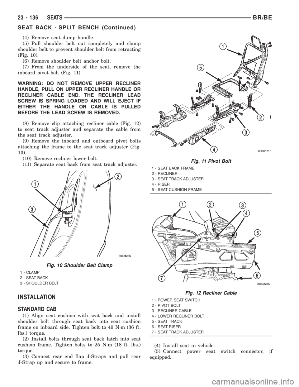
(4) Remove seat dump handle.
(5) Pull shoulder belt out completely and clamp
shoulder belt to prevent shoulder belt from retracting
(Fig. 10).
(6) Remove shoulder belt anchor bolt.
(7) From the underside of the seat, remove the
inboard pivot bolt (Fig. 11).
WARNING: DO NOT REMOVE UPPER RECLINER
HANDLE, PULL ON UPPER RECLINER HANDLE OR
RECLINER CABLE END. THE RECLINER LEAD
SCREW IS SPRING LOADED AND WILL EJECT IF
EITHER THE HANDLE OR CABLE IS PULLED
BEFORE THE LEAD SCREW IS REMOVED.
(8) Remove clip attaching recliner cable (Fig. 12)
to seat track adjuster and separate the cable from
the seat track adjuster.
(9) Remove the inboard and outboard pivot bolts
attaching the frame to the seat track adjuster (Fig.
13).
(10) Remove recliner lower bolt.
(11) Separate seat back from seat track adjuster.
INSTALLATION
STANDARD CAB
(1) Align seat cushion with seat back and install
shoulder bolt through seat back into seat cushion
frame on inboard side. Tighten bolt to 49 N´m (36 ft.
lbs.) torque.
(2) Install bolts through seat back latch into seat
cushion frame. Tighten bolts to 25 N´m (18 ft. lbs.)
torque.
(3) Connect rear end flap J-Straps and pull rear
J-Strap up and secure to frame.(4) Install seat in vehicle.
(5) Connect power seat switch connector, if
equipped.
Fig. 10 Shoulder Belt Clamp
1 - CLAMP
2 - SEAT BACK
3 - SHOULDER BELT
Fig. 11 Pivot Bolt
1 - SEAT BACK FRAME
2 - RECLINER
3 - SEAT TRACK ADJUSTER
4 - RISER
5 - SEAT CUSHION FRAME
Fig. 12 Recliner Cable
1 - POWER SEAT SWITCH
2 - PIVOT BOLT
3 - RECLINER CABLE
4 - LOWER RECLINER BOLT
5 - SEAT TRACK
6 - SEAT RISER
7 - SEAT TRACK ADJUSTER
23 - 136 SEATSBR/BE
SEAT BACK - SPLIT BENCH (Continued)
Page 2105 of 2255
(3) Engage J-Straps at base of seat back.
(4) Align lumbar handle with lumbar cam and tap
on with rubber mallet until seated.
(5) Install latch release bezel.
(6) Install latch release knob.
(7) Install seat back. (Refer to 23 - BODY/SEATS/
SEAT BACK - SPLIT BENCH - INSTALLATION)
SEAT BACK RECLINER
REMOVAL
(1) Remove seat back. (Refer to 23 - BODY/SEATS/
SEAT BACK - SPLIT BENCH - REMOVAL)
(2) Disengage J-straps at base of seat back and
roll seat back cover upward to access rubber bellows
push-in fasteners.
NOTE: Notice the routing of the recliner cable for
installation.
(3) Remove the push-in fasteners attaching upper
rubber bellows to the seat back frame.
(4) Remove rubber bellows.
(5) Remove seat dump handle, 2±door ªBEº vehi-
cles only.
WARNING: Do not pull on upper recliner handle or
recliner cable end. The recliner lead screw is spring
loaded and will eject if either the handle or cable is
pulled before the lead screw is removed.
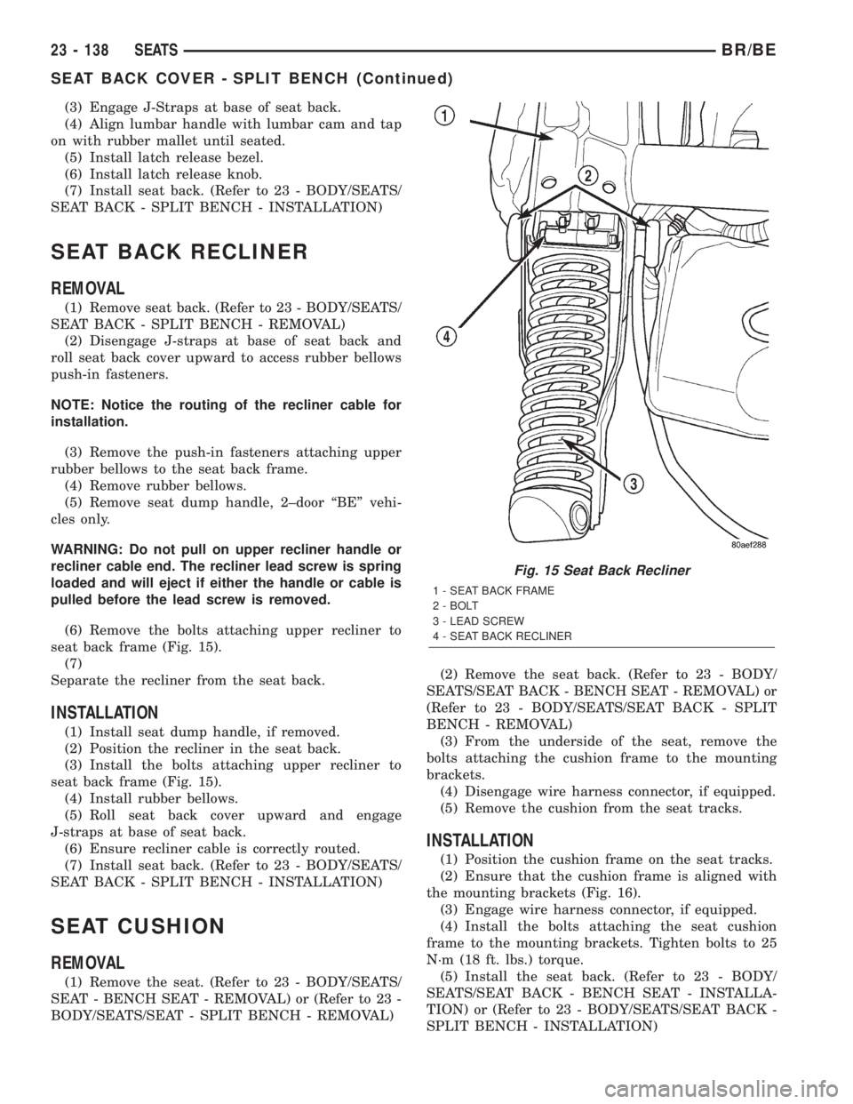
(6) Remove the bolts attaching upper recliner to
seat back frame (Fig. 15).
(7)
Separate the recliner from the seat back.
INSTALLATION
(1) Install seat dump handle, if removed.
(2) Position the recliner in the seat back.
(3) Install the bolts attaching upper recliner to
seat back frame (Fig. 15).
(4) Install rubber bellows.
(5) Roll seat back cover upward and engage
J-straps at base of seat back.
(6) Ensure recliner cable is correctly routed.
(7) Install seat back. (Refer to 23 - BODY/SEATS/
SEAT BACK - SPLIT BENCH - INSTALLATION)
SEAT CUSHION
REMOVAL
(1) Remove the seat. (Refer to 23 - BODY/SEATS/
SEAT - BENCH SEAT - REMOVAL) or (Refer to 23 -
BODY/SEATS/SEAT - SPLIT BENCH - REMOVAL)(2) Remove the seat back. (Refer to 23 - BODY/
SEATS/SEAT BACK - BENCH SEAT - REMOVAL) or
(Refer to 23 - BODY/SEATS/SEAT BACK - SPLIT
BENCH - REMOVAL)
(3) From the underside of the seat, remove the
bolts attaching the cushion frame to the mounting
brackets.
(4) Disengage wire harness connector, if equipped.
(5) Remove the cushion from the seat tracks.
INSTALLATION
(1) Position the cushion frame on the seat tracks.
(2) Ensure that the cushion frame is aligned with
the mounting brackets (Fig. 16).
(3) Engage wire harness connector, if equipped.
(4) Install the bolts attaching the seat cushion
frame to the mounting brackets. Tighten bolts to 25
N´m (18 ft. lbs.) torque.
(5) Install the seat back. (Refer to 23 - BODY/
SEATS/SEAT BACK - BENCH SEAT - INSTALLA-
TION) or (Refer to 23 - BODY/SEATS/SEAT BACK -
SPLIT BENCH - INSTALLATION)
Fig. 15 Seat Back Recliner
1 - SEAT BACK FRAME
2 - BOLT
3 - LEAD SCREW
4 - SEAT BACK RECLINER
23 - 138 SEATSBR/BE
SEAT BACK COVER - SPLIT BENCH (Continued)
Page 2110 of 2255
EASY ENTRY SEAT TRACK
REMOVAL
(1) Remove front passenger seat. (Refer to 23 -
BODY/SEATS/SEAT - SPLIT BENCH - REMOVAL)
(2) Remove recliner handle.
(3) Remove side shield.
(4) Disengage seat track latch release cables.
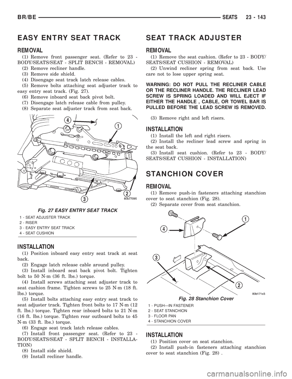
(5) Remove bolts attaching seat adjuster track to
easy entry seat track. (Fig. 27).
(6) Remove inboard seat back pivot bolt.
(7) Disengage latch release cable from pulley.
(8) Separate seat adjuster track from seat back.
INSTALLATION
(1) Position inboard easy entry seat track at seat
back.
(2) Engage latch release cable around pulley.
(3) Install inboard seat back pivot bolt. Tighten
bolt to 50 N´m (36 ft. lbs.) torque.
(4) Install screws attaching seat adjuster track to
seat cushion frame. Tighten screws to 25 N´m (18 ft.
lbs.) torque.
(5) Install bolts attaching easy entry seat track to
seat adjuster track. Tighten front bolts to 17 N´m (12
ft. lbs.) torque. Tighten rear inboard bolts to 21 N´m
(16 ft. lbs.) torque. Tighten rear outboard bolts to 45
N´m (33 ft. lbs.) torque.
(6) Engage seat track latch release cables.
(7) Install front passenger seat. (Refer to 23 -
BODY/SEATS/SEAT - SPLIT BENCH - INSTALLA-
TION)
(8) Install side shield.
(9) Install recliner handle.
SEAT TRACK ADJUSTER
REMOVAL
(1) Remove the seat cushion. (Refer to 23 - BODY/
SEATS/SEAT CUSHION - REMOVAL)
(2) Unwind recliner spring from seat back. Use
care not to lose upper spring seat.
WARNING: DO NOT PULL THE RECLINER CABLE
OR THE RECLINER HANDLE. THE RECLINER LEAD
SCREW IS SPRING LOADED AND WILL EJECT IF
EITHER THE HANDLE , CABLE, OR TOWEL BAR IS
PULLED BEFORE THE LEAD SCREW IS REMOVED.
(3) Remove right and left risers.
INSTALLATION
(1) Install the left and right risers.
(2) Install the recliner lead screw and spring in
the seat back.
(3) Install seat cushion. (Refer to 23 - BODY/
SEATS/SEAT CUSHION - INSTALLATION)
STANCHION COVER
REMOVAL
(1) Remove push-in fasteners attaching stanchion
cover to seat stanchion (Fig. 28).
(2) Separate cover from seat stanchion.
INSTALLATION
(1) Position cover on seat stanchion.
(2) Install push-in fasteners attaching stanchion
cover to seat stanchion (Fig. 28) .
Fig. 27 EASY ENTRY SEAT TRACK
1 - SEAT ADJUSTER TRACK
2 - RISER
3 - EASY ENTRY SEAT TRACK
4 - SEAT CUSHION
Fig. 28 Stanchion Cover
1 - PUSHÐIN FASTENER
2 - SEAT STANCHION
3 - FLOOR PAN
4 - STANCHION COVER
BR/BESEATS 23 - 143