2002 DODGE RAM warning
[x] Cancel search: warningPage 1363 of 2255
REMOVAL
Refer to maintenance schedules in this manual for
recommended fuel filter replacement intervals.
Draining water from fuel filter/water separa-
tor housing:
The housing drain valve (Fig. 14) serves two pur-
poses. One is topartiallydrain filter housing of
excess water. The other is tocompletelydrain hous-
ing for fuel filter, drain valve, heater element or
water-in-fuel sensor replacement.
The filter housing should be partially drained
whenever water-in-fuel warning lamp remains illumi-
nated. (Note that lamp will be illuminated for
approximately two seconds when ignition key is ini-
tially placed in ON position for a bulb check).
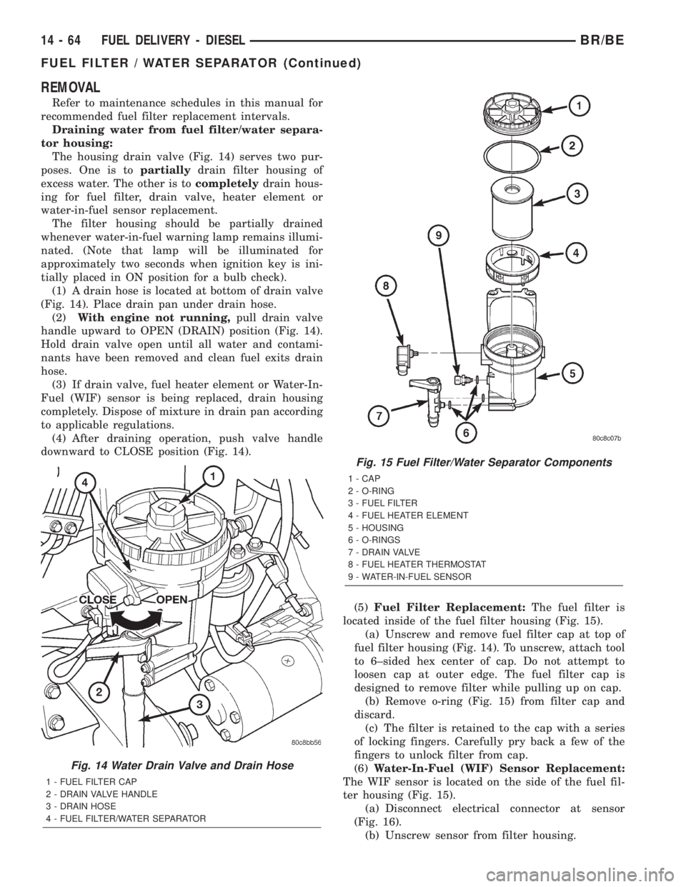
(1) A drain hose is located at bottom of drain valve
(Fig. 14). Place drain pan under drain hose.
(2)With engine not running,pull drain valve
handle upward to OPEN (DRAIN) position (Fig. 14).
Hold drain valve open until all water and contami-
nants have been removed and clean fuel exits drain
hose.
(3) If drain valve, fuel heater element or Water-In-
Fuel (WIF) sensor is being replaced, drain housing
completely. Dispose of mixture in drain pan according
to applicable regulations.
(4) After draining operation, push valve handle
downward to CLOSE position (Fig. 14).
(5)Fuel Filter Replacement:The fuel filter is
located inside of the fuel filter housing (Fig. 15).
(a) Unscrew and remove fuel filter cap at top of
fuel filter housing (Fig. 14). To unscrew, attach tool
to 6±sided hex center of cap. Do not attempt to
loosen cap at outer edge. The fuel filter cap is
designed to remove filter while pulling up on cap.
(b) Remove o-ring (Fig. 15) from filter cap and
discard.
(c) The filter is retained to the cap with a series
of locking fingers. Carefully pry back a few of the
fingers to unlock filter from cap.
(6)Water-In-Fuel (WIF) Sensor Replacement:
The WIF sensor is located on the side of the fuel fil-
ter housing (Fig. 15).
(a) Disconnect electrical connector at sensor
(Fig. 16).
(b) Unscrew sensor from filter housing.
Fig. 14 Water Drain Valve and Drain Hose
1 - FUEL FILTER CAP
2 - DRAIN VALVE HANDLE
3 - DRAIN HOSE
4 - FUEL FILTER/WATER SEPARATOR
Fig. 15 Fuel Filter/Water Separator Components
1 - CAP
2 - O-RING
3 - FUEL FILTER
4 - FUEL HEATER ELEMENT
5 - HOUSING
6 - O-RINGS
7 - DRAIN VALVE
8 - FUEL HEATER THERMOSTAT
9 - WATER-IN-FUEL SENSOR
14 - 64 FUEL DELIVERY - DIESELBR/BE
FUEL FILTER / WATER SEPARATOR (Continued)
Page 1377 of 2255
DESCRIPTIONÐHIGH PRESSURE FUEL LINES
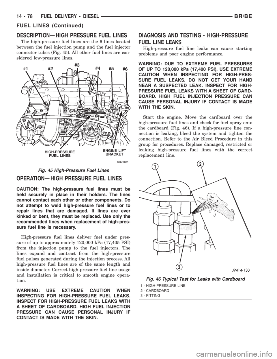
The high-pressure fuel lines are the 6 lines located
between the fuel injection pump and the fuel injector
connector tubes (Fig. 45). All other fuel lines are con-
sidered low-pressure lines.
OPERATIONÐHIGH PRESSURE FUEL LINES
CAUTION: The high-pressure fuel lines must be
held securely in place in their holders. The lines
cannot contact each other or other components. Do
not attempt to weld high-pressure fuel lines or to
repair lines that are damaged. If lines are ever
kinked or bent, they must be replaced. Use only the
recommended lines when replacement of high-pres-
sure fuel line is necessary.
High-pressure fuel lines deliver fuel under pres-
sure of up to approximately 120,000 kPa (17,405 PSI)
from the injection pump to the fuel injectors. The
lines expand and contract from the high-pressure
fuel pulses generated during the injection process. All
high-pressure fuel lines are of the same length and
inside diameter. Correct high-pressure fuel line usage
and installation is critical to smooth engine opera-
tion.
WARNING: USE EXTREME CAUTION WHEN
INSPECTING FOR HIGH-PRESSURE FUEL LEAKS.
INSPECT FOR HIGH-PRESSURE FUEL LEAKS WITH
A SHEET OF CARDBOARD. HIGH FUEL INJECTION
PRESSURE CAN CAUSE PERSONAL INJURY IF
CONTACT IS MADE WITH THE SKIN.
DIAGNOSIS AND TESTING - HIGH-PRESSURE
FUEL LINE LEAKS
High-pressure fuel line leaks can cause starting
problems and poor engine performance.
WARNING: DUE TO EXTREME FUEL PRESSURES
OF UP TO 120,000 kPa (17,400 PSI), USE EXTREME
CAUTION WHEN INSPECTING FOR HIGH-PRES-
SURE FUEL LEAKS. DO NOT GET YOUR HAND
NEAR A SUSPECTED LEAK. INSPECT FOR HIGH-
PRESSURE FUEL LEAKS WITH A SHEET OF CARD-
BOARD. HIGH FUEL INJECTION PRESSURE CAN
CAUSE PERSONAL INJURY IF CONTACT IS MADE
WITH THE SKIN.
Start the engine. Move the cardboard over the
high-pressure fuel lines and check for fuel spray onto
the cardboard (Fig. 46). If a high-pressure line con-
nection is leaking, bleed the system and tighten the
connection. Refer to the Air Bleed Procedure in this
group for procedures. Replace damaged, restricted or
leaking high-pressure fuel lines with the correct
replacement line.
Fig. 45 High-Pressure Fuel Lines
Fig. 46 Typical Test for Leaks with Cardboard
1 - HIGH-PRESSURE LINE
2 - CARDBOARD
3 - FITTING
14 - 78 FUEL DELIVERY - DIESELBR/BE
FUEL LINES (Continued)
Page 1385 of 2255
(7) Because fuel pump relay was removed, a Diag-
nostic Trouble Code (DTC) may have been set. After
testing is completed, and relay has been installed,
use DRB scan tool to remove DTC.
Fuel Supply Restriction Test:
Due to very small vacuum specifications, the DRB
scan tool along with the Periphal Expansion Port
(PEP) Module and 0±15 psi transducer must be used.
(8) Verify transfer pump pressure is OK before
performing restriction test.
(9) Locate and disconnect fuel supply line quick-
connect fitting at left-rear of engine (Fig. 63). After
disconnecting line, plastic clip will remain attached
to metal fuel line at engine. Carefully remove clip
from metal line. Snap same clip into fuel supply
hose.
(10) Install Special Rubber Adapter Hose Tool
6631 (3/8º) into ends of disconnected fuel supply line.
(11) Install transducer from PEP module to brass
ªTº fitting on tool 6631.
(12) Hook up DRB scan tool to transducer.
WARNING: DO NOT STAND IN LINE WITH THE
COOLING FAN FOR THE FOLLOWING STEPS.
(13) Start engine and record vacuum reading with
engine speed at high-idle (high-idle means engine
speed is at 100 percent throttle and no load). The
fuel restriction testMUSTbe done with engine speed
at high-idle.
(14) If vacuum reading islessthan 6 in/hg. (0±152
mm hg.), test is OK. If vacuum reading ishigher
than 6 in/hg. (152 mm hg.), restriction exists in fuel
supply line or in fuel tank module. Check fuel supply
line for damage, dents or kinking. If OK, remove
module and check module and lines for blockage.
Also check fuel pump inlet filter at bottom of module
for obstructions.
Testing For Air Leaks in Fuel Supply Side:
(15) A 3±foot section of 3/8º I.D. clear tubing is
required for this test.
(16) Using a tire core valve removal tool, carefully
remove core valve from inlet fitting test port.
(17) Attach and clamp the 3/8ºclear hose to fitting
nipple.
(18) Place other end of hose into a large clear con-
tainer. Allow hose to loop as high as possibleabove
test port.
(19) The fuel transfer pump can be put into a 25
second run (test) mode if key is quickly turned to
crank position and released back to run position
without starting engine.
To prevent engine from starting in this test, first
remove fuel system relay (fuel injection pump relay).
Relay is located in Power Distribution Center (PDC).
Refer to label under PDC cover for relay location.
Because fuel pump relay was removed, a DiagnosticTrouble Code (DTC) may have been set. After testing
is completed, and relay has been installed, use DRB
scan tool to remove DTC.
(20) Allow air to purge from empty hose before
examining for air bubbles. Air bubbles should not be
present.
(21) If bubbles are present, check for leaks in sup-
ply line to fuel tank.
(22) If supply line is not leaking, remove fuel tank
module and remove filter at bottom of module (filter
snaps to module). Check for leaks between supply
nipple at top of module, and filter opening at bottom
of module. Replace module if necessary.
(23) After performing test, install core back into
test fitting. Before installing protective cap, be sure
fitting is not leaking.
REMOVAL
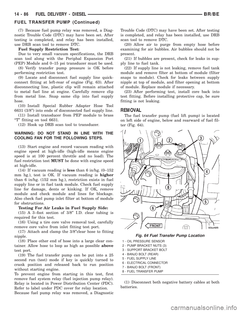
The fuel transfer pump (fuel lift pump) is located
on left side of engine, below and rearward of fuel fil-
ter (Fig. 64).
(1) Disconnect both negative battery cables at both
batteries.
Fig. 64 Fuel Transfer Pump Location
1 - OIL PRESSURE SENSOR
2 - PUMP BRACKET NUTS (3)
3 - SUPPORT BRACKET BOLT
4 - BANJO BOLT (REAR)
5 - FUEL SUPPLY LINE
6 - ELECTRICAL CONNECTOR
7 - BANJO BOLT (FRONT)
8 - FUEL TRANSFER PUMP
14 - 86 FUEL DELIVERY - DIESELBR/BE
FUEL TRANSFER PUMP (Continued)
Page 1388 of 2255
WATER IN FUEL SENSOR
DESCRIPTION
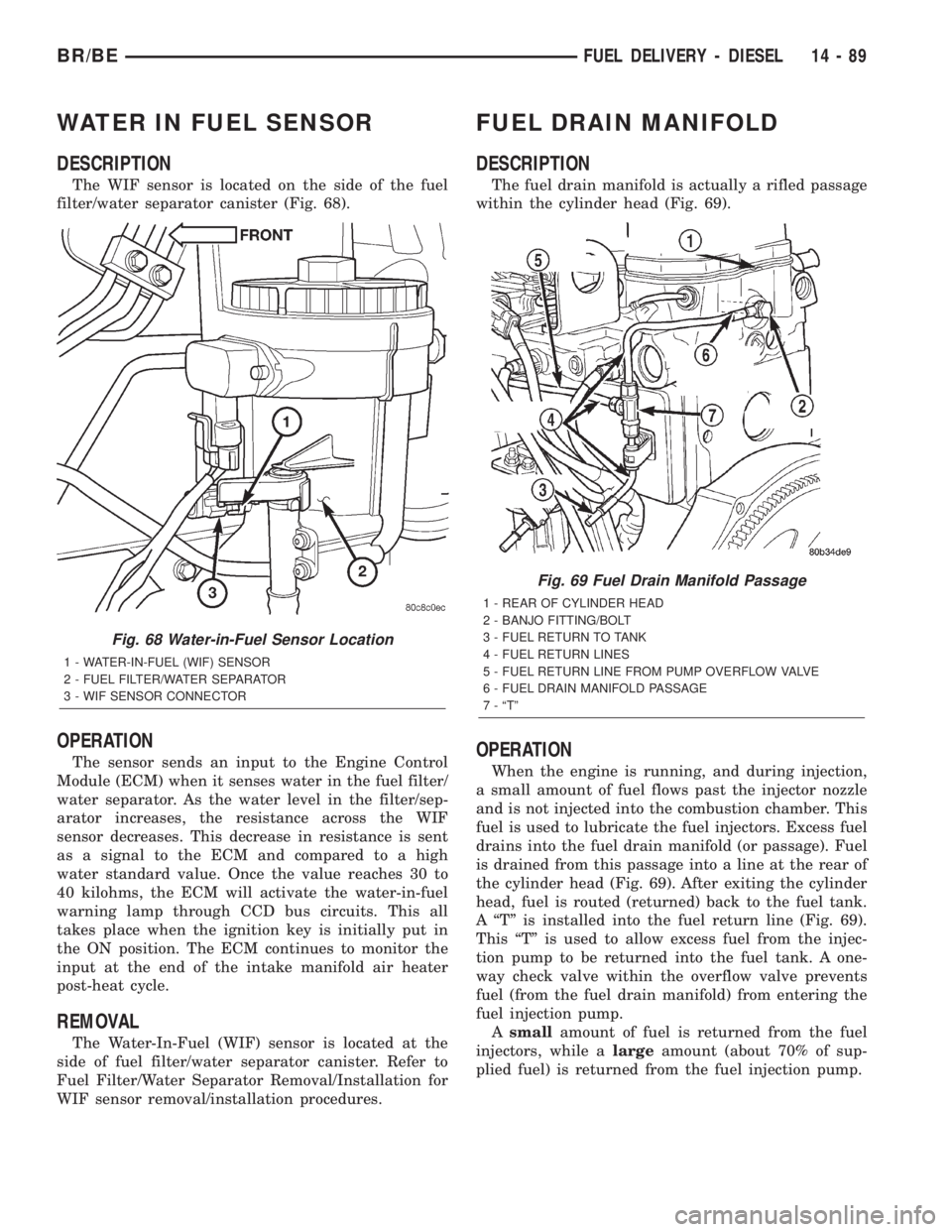
The WIF sensor is located on the side of the fuel
filter/water separator canister (Fig. 68).
OPERATION
The sensor sends an input to the Engine Control
Module (ECM) when it senses water in the fuel filter/
water separator. As the water level in the filter/sep-
arator increases, the resistance across the WIF
sensor decreases. This decrease in resistance is sent
as a signal to the ECM and compared to a high
water standard value. Once the value reaches 30 to
40 kilohms, the ECM will activate the water-in-fuel
warning lamp through CCD bus circuits. This all
takes place when the ignition key is initially put in
the ON position. The ECM continues to monitor the
input at the end of the intake manifold air heater
post-heat cycle.
REMOVAL
The Water-In-Fuel (WIF) sensor is located at the
side of fuel filter/water separator canister. Refer to
Fuel Filter/Water Separator Removal/Installation for
WIF sensor removal/installation procedures.
FUEL DRAIN MANIFOLD
DESCRIPTION
The fuel drain manifold is actually a rifled passage
within the cylinder head (Fig. 69).
OPERATION
When the engine is running, and during injection,
a small amount of fuel flows past the injector nozzle
and is not injected into the combustion chamber. This
fuel is used to lubricate the fuel injectors. Excess fuel
drains into the fuel drain manifold (or passage). Fuel
is drained from this passage into a line at the rear of
the cylinder head (Fig. 69). After exiting the cylinder
head, fuel is routed (returned) back to the fuel tank.
A ªTº is installed into the fuel return line (Fig. 69).
This ªTº is used to allow excess fuel from the injec-
tion pump to be returned into the fuel tank. A one-
way check valve within the overflow valve prevents
fuel (from the fuel drain manifold) from entering the
fuel injection pump.
Asmallamount of fuel is returned from the fuel
injectors, while alargeamount (about 70% of sup-
plied fuel) is returned from the fuel injection pump.
Fig. 68 Water-in-Fuel Sensor Location
1 - WATER-IN-FUEL (WIF) SENSOR
2 - FUEL FILTER/WATER SEPARATOR
3 - WIF SENSOR CONNECTOR
Fig. 69 Fuel Drain Manifold Passage
1 - REAR OF CYLINDER HEAD
2 - BANJO FITTING/BOLT
3 - FUEL RETURN TO TANK
4 - FUEL RETURN LINES
5 - FUEL RETURN LINE FROM PUMP OVERFLOW VALVE
6 - FUEL DRAIN MANIFOLD PASSAGE
7 - ªTº
BR/BEFUEL DELIVERY - DIESEL 14 - 89
Page 1398 of 2255
lines before opening up any fuel system component.
Always cover or cap any open fuel connections before
a fuel system repair is performed.
Each fuel injector connector tube contains an edge
filter (Fig. 13) that breaks up small contaminants
that enter the injector. The edge filter uses the injec-
tors pulsating high-pressure to break up most parti-
cles so they are small enough to pass through the
injector.The edge filters are not a substitute for
proper cleaning and covering of all fuel system
components during repair.
The bottom of each fuel injector is sealed to the
cylinder head with a1.5mmthick copper shim (gas-
ket) (Fig. 12). The correct thickness shim must
always be re-installed after removing an injector.
Fuel pressure in the injector circuit decreases after
injection. The injector needle valve is immediately
closed by the needle valve spring and fuel flow into
the combustion chamber is stopped. Exhaust gases
are prevented from entering the injector nozzle by
the needle valve.
DIAGNOSIS AND TESTINGÐFUEL INJECTOR
TEST
The fuel injectors are located in the top of the cyl-
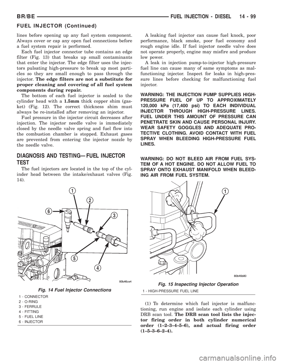
inder head between the intake/exhaust valves (Fig.
14).A leaking fuel injector can cause fuel knock, poor
performance, black smoke, poor fuel economy and
rough engine idle. If fuel injector needle valve does
not operate properly, engine may misfire and produce
low power.
A leak in injection pump-to-injector high-pressure
fuel line can cause many of same symptoms as mal-
functioning injector. Inspect for leaks in high-pres-
sure lines before checking for malfunctioning fuel
injector.
WARNING: THE INJECTION PUMP SUPPLIES HIGH-
PRESSURE FUEL OF UP TO APPROXIMATELY
120,000 kPa (17,400 psi) TO EACH INDIVIDUAL
INJECTOR THROUGH HIGH-PRESSURE LINES.
FUEL UNDER THIS AMOUNT OF PRESSURE CAN
PENETRATE SKIN AND CAUSE PERSONAL INJURY.
WEAR SAFETY GOGGLES AND ADEQUATE PRO-
TECTIVE CLOTHING. AVOID CONTACT WITH FUEL
SPRAY WHEN BLEEDING HIGH-PRESSURE FUEL
LINES.
WARNING: DO NOT BLEED AIR FROM FUEL SYS-
TEM OF A HOT ENGINE. DO NOT ALLOW FUEL TO
SPRAY ONTO EXHAUST MANIFOLD WHEN BLEED-
ING AIR FROM FUEL SYSTEM.
(1) To determine which fuel injector is malfunc-
tioning, run engine and isolate each cylinder using
DRB scan tool.The DRB scan tool lists the injec-
tor firing order in both cylinder numerical
order (1±2±3±4±5±6), and actual firing order
(1±5±3±6±2±4).
Fig. 14 Fuel Injector Connections
1 - CONNECTOR
2 - O-RING
3 - FERRULE
4 - FITTING
5 - FUEL LINE
6 - INJECTOR
Fig. 15 Inspecting Injector Operation
1 - HIGH-PRESSURE FUEL LINE
BR/BEFUEL INJECTION - DIESEL 14 - 99
FUEL INJECTOR (Continued)
Page 1399 of 2255
(2) Note RPM drop for each cylinder. As an alter-
native, loosen high-pressure fuel line fitting at fuel
injector connector tube (Fig. 15). Listen for a change
in engine speed. After testing, tighten line fitting to
40 N´m (30 ft. lbs.) torque. If engine speed drops,
injector was operating normally. If engine speed
remains same, injector may be malfunctioning. Test
all injectors in same manner one at a time.(3) Once injector has been found to be malfunc-
tioning, remove it from engine and test it. Refer to
Fuel Injector Removal/Installation.
WARNING: FUEL INJECTOR TESTERS CAN
DEVELOP EXTREMELY HIGH PRESSURES. FUEL
UNDER THIS AMOUNT OF PRESSURE CAN PENE-
TRATE SKIN AND CAUSE PERSONAL INJURY.
WEAR SAFETY GOGGLES AND ADEQUATE PRO-
TECTIVE CLOTHING. AVOID CONTACT WITH FUEL
SPRAY WHEN OPERATING INJECTOR TESTOR.
(4)
After injector has been removed, obtain bench-
mount fuel injector tester OTCt(SPXt) part number
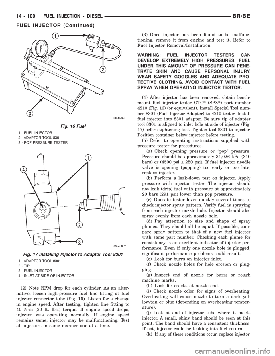
4210 (Fig. 16) (or equivalent). Install Special Tool num-
ber 8301 (Fuel Injector Adapter) to 4210 tester. Install
fuel injector into 8301 adapter. Be sure tip of adapter
tool 8301 is aligned to inlet hole at side of injector (Fig.
17) before tightening tool. Tighten tool 8301 to injector.
Position container below injector before testing.
(5) Refer to operating instructions supplied with
pressure tester for procedures.
(a) Check opening pressure or ªpopº pressure.
Pressure should be approximately 31,026 kPa (310
bars) or (4500 psi 250 psi). If fuel injector needle
valve is opening (popping) too early or too late,
replace injector.
(b) Perform a leak-down test on injector. Apply
pressure with injector tester. The injector should
not leak (drip) fuel with pressure at approximately
20 bars (291 psi) lower than pop pressure.
(c) Operate tester lever quickly several times to
check injector spray pattern. Verify fuel is spraying
from each injector nozzle hole. Injector should also
spray evenly from each nozzle hole.
(d) Pay attention to size and shape of spray
plumes. They should all be equal. If possible, com-
pare spray pattern to that of a new fuel injector
with same part number. Checking each plume for
consistency is an excellent indicator of injector per-
formance. Even if only one nozzle hole is plugged,
significant performance problems could result.
(e) Look for burrs on injector inlet.
(f) Check nozzle holes for hole erosion or plug-
ging.
(g) Inspect end of nozzle for burrs or rough
machine marks.
(h) Look for cracks at nozzle end.
(i) Check nozzle color for signs of overheating.
Overheating will cause nozzle to turn a dark yel-
low/tan or blue (depending on overheating temper-
ature).
(j)
Look at end of injector tube where it meets
injector. A small, shiny band should be seen at this
point. The band should have a consistent thickness.
If not, injector could be leaking into fuel return.
(k)If any of these conditions occur, replace injector.
Fig. 16 Fuel
1 - FUEL INJECTOR
2 - ADAPTOR TOOL 8301
3 - POP PRESSURE TESTER
Fig. 17 Installing Injector to Adaptor Tool 8301
1 - ADAPTOR TOOL 8301
2 - TIP
3 - FUEL INJECTOR
4 - INLET AT SIDE OF INJECTOR
14 - 100 FUEL INJECTION - DIESELBR/BE
FUEL INJECTOR (Continued)
Page 1415 of 2255
COLUMN
TABLE OF CONTENTS
page page
COLUMN
DESCRIPTION..........................6
OPERATION
SERVICE PRECAUTIONS................6
REMOVAL.............................6
INSTALLATION..........................8
SPECIFICATIONS
TORQUE CHART......................9
KEY-IN IGNITION SWITCH
DESCRIPTION..........................9
DIAGNOSIS AND TESTING - IGNITION
SWITCH AND KEY LOCK CYLINDER.......9
LOCK CYLINDER
REMOVAL.............................10INSTALLATION.........................10
IGNITION SWITCH
DESCRIPTION.........................11
OPERATION...........................11
DIAGNOSIS AND TESTING - IGNITION
SWITCH.............................11
REMOVAL.............................12
INSTALLATION.........................12
GEAR SHIFT LEVER
REMOVAL.............................14
INSTALLATION.........................15
STEERING WHEEL
REMOVAL.............................15
INSTALLATION.........................15
COLUMN
DESCRIPTION
The tilt and standard column (Fig. 1) has been
designed to be serviced as an assembly; less wiring,
switches, shrouds, steering wheel, etc. Most steering
column components can be serviced without remov-
ing the steering column from the vehicle.
OPERATION
SERVICE PRECAUTIONS
Safety goggles should be worn at all times when
working on steering columns.
To service the steering wheel, switches or the air-
bag, refer to the WARNINGS and CAUTIONS below.
WARNING: THE AIRBAG SYSTEM IS A SENSITIVE,
COMPLEX ELECTRO-MECHANICAL UNIT. BEFORE
ATTEMPTING TO DIAGNOSE, REMOVE OR INSTALL
THE AIRBAG SYSTEM COMPONENTS YOU MUST
FIRST DISCONNECT AND ISOLATE THE BATTERY
NEGATIVE (GROUND) CABLE. THEN WAIT TWO
MINUTES FOR THE SYSTEM CAPACITOR TO DIS-
CHARGE. FAILURE TO DO SO COULD RESULT IN
ACCIDENTAL DEPLOYMENT OF THE AIRBAG AND
POSSIBLE PERSONAL INJURY. THE FASTENERS,
SCREWS, AND BOLTS, ORIGINALLY USED FOR
THE AIRBAG COMPONENTS, HAVE SPECIAL COAT-INGS AND ARE SPECIFICALLY DESIGNED FOR THE
AIRBAG SYSTEM. THEY MUST NEVER BE
REPLACED WITH ANY SUBSTITUTES. ANYTIME A
NEW FASTENER IS NEEDED, REPLACE WITH THE
CORRECT FASTENERS PROVIDED IN THE SERVICE
PACKAGE OR FASTENERS LISTED IN THE PARTS
BOOKS.
CAUTION: Do not hammer on steering column shaft
or shift tube. This may cause the shaft/shift tube to
collapse or damage the bearing.
CAUTION: Do not attempt to remove the pivot pins
to disassemble the tilting mechanism. Do not
remove shaft lock plate, plate retainer, park lock
link or slider. This will damage the column (Fig. 2)
and (Fig. 3).
REMOVAL
(1) Position the front wheels straight ahead.
(2) Disconnect the negative (ground) cable from
the battery.
(3) Remove the airbag, (Refer to 8 - ELECTRICAL/
RESTRAINTS/DRIVER AIRBAG - REMOVAL).
(4) Remove the steering wheel with an appropriate
puller,(Refer to 19 - STEERING/COLUMN/STEER-
ING WHEEL - REMOVAL).
19 - 6 COLUMNBR/BE
Page 1442 of 2255
PUMP
TABLE OF CONTENTS
page page
PUMP
DESCRIPTION.........................33
OPERATION...........................33
DIAGNOSIS AND TESTING - PUMP LEAKAGE . 33
STANDARD PROCEDURE
STANDARD PROCEDURE - POWER
STEERING PUMP - INITIAL OPERATION....33
STANDARD PROCEDURE - FLUSHING
POWER STEERING SYSTEM............34
REMOVAL
REMOVAL - GASOLINE ENGINE..........35
REMOVAL - DIESEL ENGINE............36
INSTALLATION
INSTALLATION - GASOLINE ENGINE......37INSTALLATION - DIESEL ENGINE.........37
SPECIAL TOOLS
POWER STEERING PUMP..............38
PULLEY
REMOVAL.............................38
INSTALLATION.........................39
HOSES - PRESSURE
DESCRIPTION.........................39
OPERATION...........................39
HOSES - RETURN
DESCRIPTION.........................39
OPERATION...........................39
PUMP
DESCRIPTION
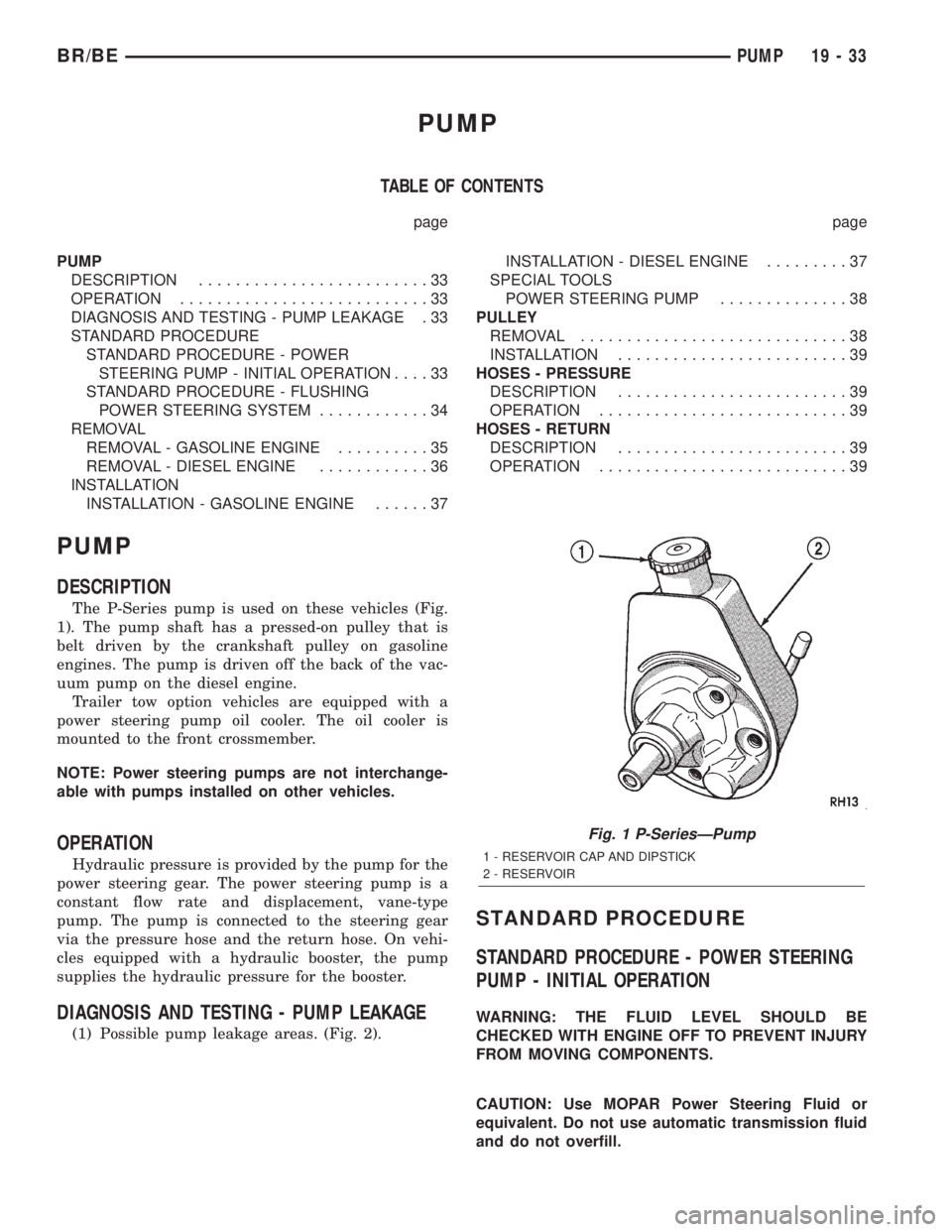
The P-Series pump is used on these vehicles (Fig.
1). The pump shaft has a pressed-on pulley that is
belt driven by the crankshaft pulley on gasoline
engines. The pump is driven off the back of the vac-
uum pump on the diesel engine.
Trailer tow option vehicles are equipped with a
power steering pump oil cooler. The oil cooler is
mounted to the front crossmember.
NOTE: Power steering pumps are not interchange-
able with pumps installed on other vehicles.
OPERATION
Hydraulic pressure is provided by the pump for the
power steering gear. The power steering pump is a
constant flow rate and displacement, vane-type
pump. The pump is connected to the steering gear
via the pressure hose and the return hose. On vehi-
cles equipped with a hydraulic booster, the pump
supplies the hydraulic pressure for the booster.
DIAGNOSIS AND TESTING - PUMP LEAKAGE
(1) Possible pump leakage areas. (Fig. 2).
STANDARD PROCEDURE
STANDARD PROCEDURE - POWER STEERING
PUMP - INITIAL OPERATION
WARNING: THE FLUID LEVEL SHOULD BE
CHECKED WITH ENGINE OFF TO PREVENT INJURY
FROM MOVING COMPONENTS.
CAUTION: Use MOPAR Power Steering Fluid or
equivalent. Do not use automatic transmission fluid
and do not overfill.
Fig. 1 P-SeriesÐPump
1 - RESERVOIR CAP AND DIPSTICK
2 - RESERVOIR
BR/BEPUMP 19 - 33