2002 DODGE RAM warning
[x] Cancel search: warningPage 943 of 2255

BRAKE PRESSURE SWITCH - BLACK 2 WAY
CAV CIRCUIT FUNCTION
1 Z1 20BK GROUND
2 G9 20GY/BK RED BRAKE WARNING INDICATOR DRIVER
BYPASS JUMPER (A/T) - GREEN 2 WAY
CAV CIRCUIT FUNCTION
1 T141 14YL/RD FUSED IGNITION SWITCH OUTPUT (START)
2 T141 14YL/RD FUSED IGNITION SWITCH OUTPUT (START)
C105 - (FOG LAMP JUMPER SIDE)
CAV CIRCUIT
1 L34 20RD/OR
2 L39 20LB
C105 - (HEADLAMP AND DASH SIDE)
CAV CIRCUIT
1 L34 20RD/OR
2 L39 20LB
C106 - BLACK (4X4 INDICATOR SIDE)
CAV CIRCUIT
1 G107 18BK/GY
2 Z1 18BK
C106 - BLACK (HEADLAMP AND DASH SIDE)
CAV CIRCUIT
1 G107 20GY
2 Z1 20BK
8W - 80 - 8 8W-80 CONNECTOR PIN-OUTSBR/BE
Page 977 of 2255
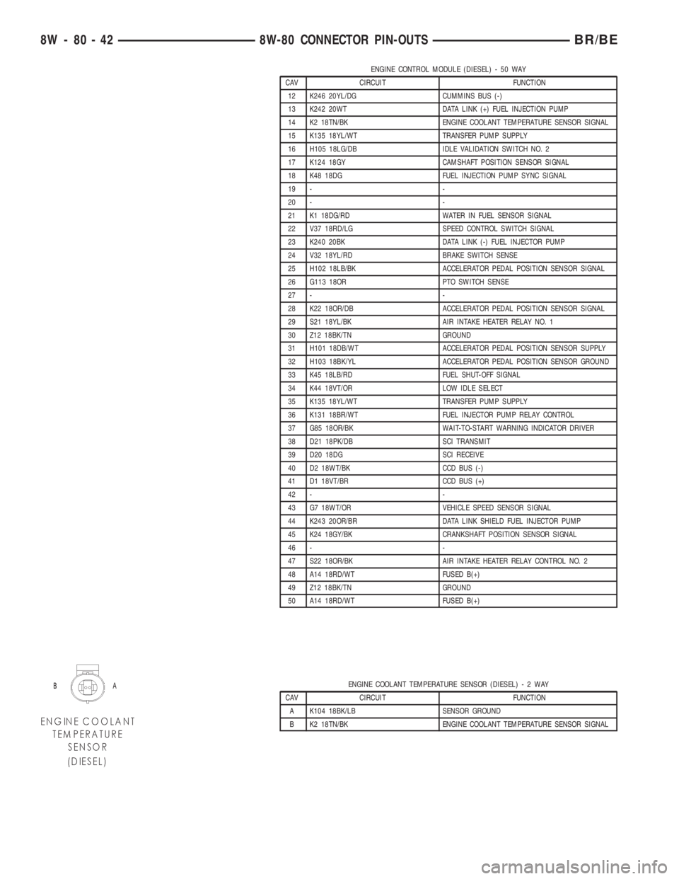
ENGINE CONTROL MODULE (DIESEL) - 50 WAY
CAV CIRCUIT FUNCTION
12 K246 20YL/DG CUMMINS BUS (-)
13 K242 20WT DATA LINK (+) FUEL INJECTION PUMP
14 K2 18TN/BK ENGINE COOLANT TEMPERATURE SENSOR SIGNAL
15 K135 18YL/WT TRANSFER PUMP SUPPLY
16 H105 18LG/DB IDLE VALIDATION SWITCH NO. 2
17 K124 18GY CAMSHAFT POSITION SENSOR SIGNAL
18 K48 18DG FUEL INJECTION PUMP SYNC SIGNAL
19 - -
20 - -
21 K1 18DG/RD WATER IN FUEL SENSOR SIGNAL
22 V37 18RD/LG SPEED CONTROL SWITCH SIGNAL
23 K240 20BK DATA LINK (-) FUEL INJECTOR PUMP
24 V32 18YL/RD BRAKE SWITCH SENSE
25 H102 18LB/BK ACCELERATOR PEDAL POSITION SENSOR SIGNAL
26 G113 18OR PTO SWITCH SENSE
27 - -
28 K22 18OR/DB ACCELERATOR PEDAL POSITION SENSOR SIGNAL
29 S21 18YL/BK AIR INTAKE HEATER RELAY NO. 1
30 Z12 18BK/TN GROUND
31 H101 18DB/WT ACCELERATOR PEDAL POSITION SENSOR SUPPLY
32 H103 18BK/YL ACCELERATOR PEDAL POSITION SENSOR GROUND
33 K45 18LB/RD FUEL SHUT-OFF SIGNAL
34 K44 18VT/OR LOW IDLE SELECT
35 K135 18YL/WT TRANSFER PUMP SUPPLY
36 K131 18BR/WT FUEL INJECTOR PUMP RELAY CONTROL
37 G85 18OR/BK WAIT-TO-START WARNING INDICATOR DRIVER
38 D21 18PK/DB SCI TRANSMIT
39 D20 18DG SCI RECEIVE
40 D2 18WT/BK CCD BUS (-)
41 D1 18VT/BR CCD BUS (+)
42 - -
43 G7 18WT/OR VEHICLE SPEED SENSOR SIGNAL
44 K243 20OR/BR DATA LINK SHIELD FUEL INJECTOR PUMP
45 K24 18GY/BK CRANKSHAFT POSITION SENSOR SIGNAL
46 - -
47 S22 18OR/BK AIR INTAKE HEATER RELAY CONTROL NO. 2
48 A14 18RD/WT FUSED B(+)
49 Z12 18BK/TN GROUND
50 A14 18RD/WT FUSED B(+)
ENGINE COOLANT TEMPERATURE SENSOR (DIESEL)-2WAY
CAV CIRCUIT FUNCTION
A K104 18BK/LB SENSOR GROUND
B K2 18TN/BK ENGINE COOLANT TEMPERATURE SENSOR SIGNAL
8W - 80 - 42 8W-80 CONNECTOR PIN-OUTSBR/BE
Page 984 of 2255
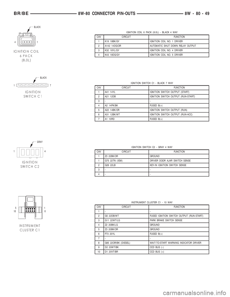
IGNITION COIL 6 PACK (8.0L) - BLACK 4 WAY
CAV CIRCUIT FUNCTION
1 K19 18BK/GY IGNITION COIL NO. 1 DRIVER
2 A142 14DG/OR AUTOMATIC SHUT DOWN RELAY OUTPUT
3 K32 18YL/GY IGNITION COIL NO. 4 DRIVER
4 K43 18DG/GY IGNITION COIL NO. 5 DRIVER
IGNITION SWITCH C1 - BLACK 7 WAY
CAV CIRCUIT FUNCTION
1 A41 14YL IGNITION SWITCH OUTPUT (START)
2 A21 12DB IGNITION SWITCH OUTPUT (RUN-START)
3- -
4 A2 14PK/BK FUSED B(+)
5 A22 14BK/OR IGNITION SWITCH OUTPUT (RUN)
6 A31 12BK/WT IGNITION SWITCH OUTPUT (RUN-ACC)
7 A1 10RD FUSED B(+)
IGNITION SWITCH C2 - GRAY 4 WAY
CAV CIRCUIT FUNCTION
1 Z3 22BK/OR GROUND
1 G75 22TN (IEM) DRIVER DOOR AJAR SWITCH SENSE
2 G26 22LB KEY-IN IGNITION SWITCH SENSE
3- -
4- -
INSTRUMENT CLUSTER C1 - 10 WAY
CAV CIRCUIT FUNCTION
1- -
2 G5 22DB/WT FUSED IGNITION SWITCH OUTPUT (RUN-START)
3 G11 22WT/LG PARK BRAKE SWITCH SENSE
4 Z2 20BK/LG GROUND
5 Z3 20BK/OR GROUND
6 F73 20YL FUSED B(+)
7- -
8 G85 22OR/BK (DIESEL) WAIT-TO-START WARNING INDICATOR DRIVER
9 D2 20WT/BK CCD BUS (-)
10 D1 20VT/BR CCD BUS (+)
BR/BE8W-80 CONNECTOR PIN-OUTS 8W - 80 - 49
Page 1061 of 2255
tribution points for the electrical current required to
operate all of the many standard and optional facto-
ry-installed electrical and electronic powertrain,
chassis, safety, security, comfort and convenience sys-
tems. At the same time, the power distribution sys-
tem was designed to provide ready access to these
electrical distribution points for the vehicle techni-
cian to use when conducting diagnosis and repair of
faulty circuits. The power distribution system can
also prove useful for the sourcing of additional elec-
trical circuits that may be required to provide the
electrical current needed to operate many accessories
that the vehicle owner may choose to have installed
in the aftermarket.
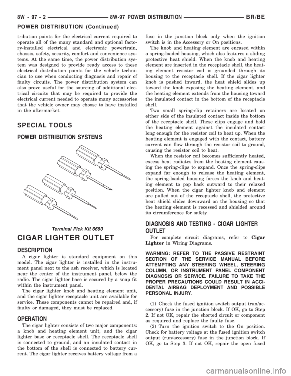
SPECIAL TOOLS
POWER DISTRIBUTION SYSTEMS
CIGAR LIGHTER OUTLET
DESCRIPTION
A cigar lighter is standard equipment on this
model. The cigar lighter is installed in the instru-
ment panel next to the ash receiver, which is located
near the center of the instrument panel, below the
radio. The cigar lighter base is secured by a snap fit
within the instrument panel.
The cigar lighter knob and heating element unit,
and the cigar lighter receptacle unit are available for
service. These components cannot be repaired and, if
faulty or damaged, they must be replaced.
OPERATION
The cigar lighter consists of two major components:
a knob and heating element unit, and the cigar
lighter base or receptacle shell. The receptacle shell
is connected to ground, and an insulated contact in
the bottom of the shell is connected to battery cur-
rent. The cigar lighter receives battery voltage from afuse in the junction block only when the ignition
switch is in the Accessory or On positions.
The knob and heating element are encased within
a spring-loaded housing, which also features a sliding
protective heat shield. When the knob and heating
element are inserted in the receptacle shell, the heat-
ing element resistor coil is grounded through its
housing to the receptacle shell. If the cigar lighter
knob is pushed inward, the heat shield slides up
toward the knob exposing the heating element, and
the heating element extends from the housing toward
the insulated contact in the bottom of the receptacle
shell.
Two small spring-clip retainers are located on
either side of the insulated contact inside the bottom
of the receptacle shell. These clips engage and hold
the heating element against the insulated contact
long enough for the resistor coil to heat up. When the
heating element is engaged with the contact, battery
current can flow through the resistor coil to ground,
causing the resistor coil to heat.
When the resistor coil becomes sufficiently heated,
excess heat radiates from the heating element caus-
ing the spring-clips to expand. Once the spring-clips
expand far enough to release the heating element,
the spring-loaded housing forces the knob and heat-
ing element to pop back outward to their relaxed
position. When the cigar lighter knob and element
are pulled out of the receptacle shell, the protective
heat shield slides downward on the housing so that
the heating element is recessed and shielded around
its circumference for safety.
DIAGNOSIS AND TESTING - CIGAR LIGHTER
OUTLET
For complete circuit diagrams, refer toCigar
Lighterin Wiring Diagrams.
WARNING: REFER TO THE PASSIVE RESTRAINT
SECTION OF THE SERVICE MANUAL BEFORE
ATTEMPTING ANY STEERING WHEEL, STEERING
COLUMN, OR INSTRUMENT PANEL COMPONENT
DIAGNOSIS OR SERVICE. FAILURE TO TAKE THE
PROPER PRECAUTIONS COULD RESULT IN ACCI-
DENTAL AIRBAG DEPLOYMENT AND POSSIBLE
PERSONAL INJURY.
(1) Check the fused ignition switch output (run/ac-
cessory) fuse in the junction block. If OK, go to Step
2. If not OK, repair the shorted circuit or component
as required and replace the faulty fuse.
(2) Turn the ignition switch to the On position.
Check for battery voltage at the fused ignition switch
output (run/accessory) fuse in the junction block. If
OK, go to Step 3. If not OK, repair the open fused
Terminal Pick Kit 6680
8W - 97 - 2 8W-97 POWER DISTRIBUTIONBR/BE
POWER DISTRIBUTION (Continued)
Page 1066 of 2255
tor between many of the engine compartment, instru-
ment panel, and body wire harnesses. The JB houses
up to nineteen blade-type fuses (two standard-type
and seventeen mini-type), up to two blade-type auto-
matic resetting circuit breakers, the electronic combi-
nation turn signal and hazard warning flasher, and
one International Standards Organization (ISO)
micro-relay.
The molded plastic JB housing has integral mount-
ing brackets that are secured with two screws to the
left instrument panel end bracket. The left end of the
instrument panel cover has a snap-fit fuse access
panel that can be removed for service of the JB. A
fuse puller and spare fuse holders are located on the
back of the fuse access cover, as well as an adhesive-
backed fuse layout map to ensure proper fuse identi-
fication.
The JB unit cannot be repaired and is only ser-
viced as an assembly. If any internal circuit or the JB
housing is faulty or damaged, the entire JB unit
must be replaced.
OPERATION
All of the circuits entering and leaving the JB do
so through up to nine wire harness connectors, which
are connected to the JB through integral connector
receptacles molded into the JB housing. Internal con-
nection of all of the JB circuits is accomplished by an
intricate combination of hard wiring and bus bars.
Refer toWiring Diagramsfor the location of com-
plete JB circuit diagrams.
DIAGNOSIS AND TESTING - JUNCTION BLOCK
The junction block does not incorporate any self
diagnostic capability. Most of the electrical circuits
incorporated into the vehicle must pass through the
junction block at one point or another. The most effi-
cient means of diagnosing a suspected junction block
problem involves a simple continuity tester or ohm
meter. Using the Wiring Diagrams as a guide trace
the problem circuit to the proper junction block cav-
ity and test all circuits in the effected circuit for
proper continuity. A open or high resistance circuit is
a sign of a problem. Some other possible junction
block problems to look for are:
²Loose fuse receptacle terminals.
²Loose relay / circuit breaker receptacle termi-
nals.
²Bent or distorted electrical circuit pins.
²Incorrect size fuse installed in junction block
fuse cavity.
²Dark areas identifying a source of excess heat.
²Defective fuse, relay or circuit breaker installed
in junction block cavity.
REMOVAL
(1) Disconnect and isolate the battery negative
cable.
(2) Remove the fuse access bezel from the instru-
ment panel.
(3) Remove the steering column cover (Refer to 23
- BODY/INSTRUMENT PANEL/STEERING COL-
UMN OPENING COVER - REMOVAL).
(4) Remove the hood release handle retaining
screws and position the handle assembly out of the
way.
(5) Remove the lower knee blocker from the instru-
ment panel.
(6) Pull drivers side carpet down, out of the way.
(7) Remove the parking brake switch connector,
release linkage and retaining fasteners and position
the assembly out the drivers door opening.
(8) Remove the electrical ground connections,
located behind park brake mounting location.
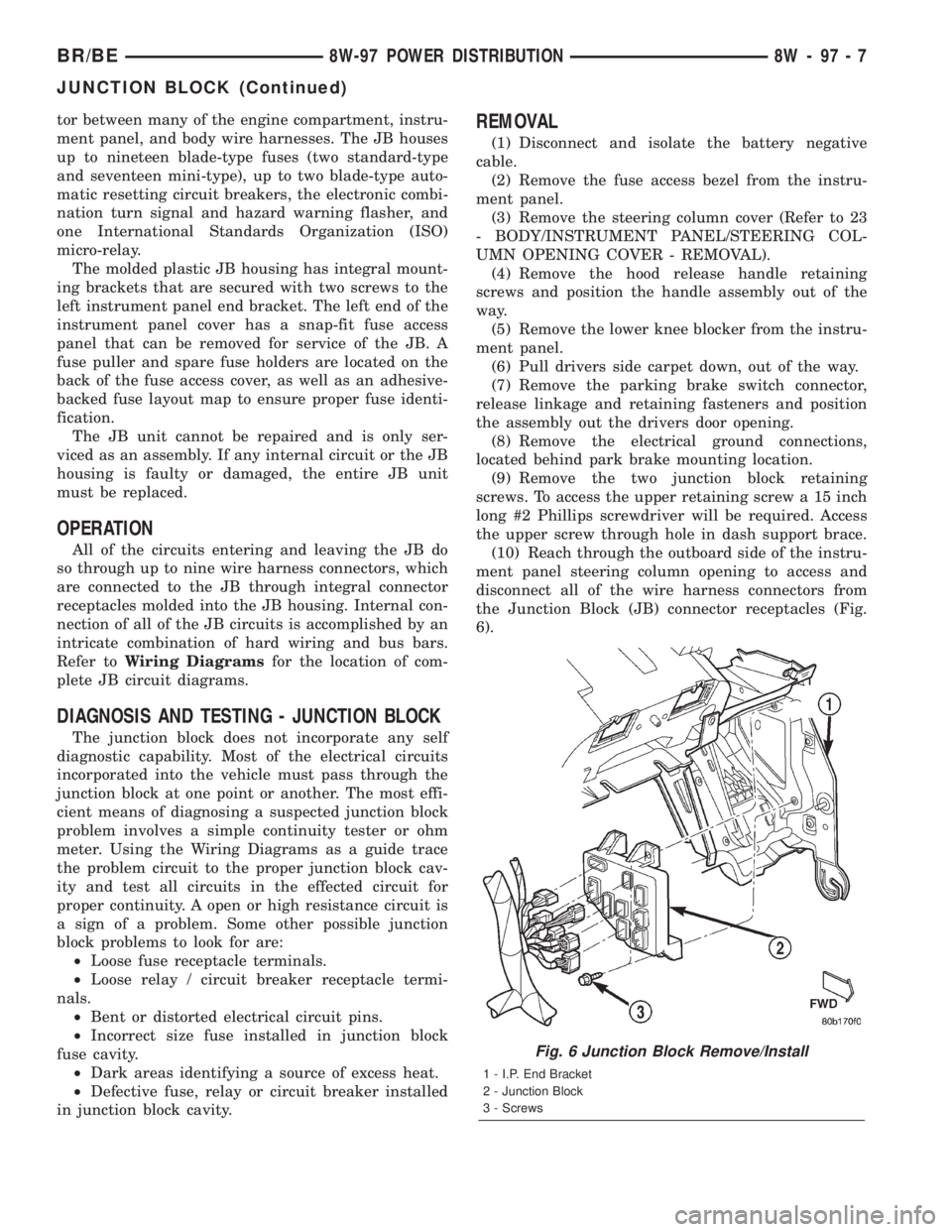
(9) Remove the two junction block retaining
screws. To access the upper retaining screw a 15 inch
long #2 Phillips screwdriver will be required. Access
the upper screw through hole in dash support brace.
(10) Reach through the outboard side of the instru-
ment panel steering column opening to access and
disconnect all of the wire harness connectors from
the Junction Block (JB) connector receptacles (Fig.
6).
Fig. 6 Junction Block Remove/Install
1 - I.P. End Bracket
2 - Junction Block
3 - Screws
BR/BE8W-97 POWER DISTRIBUTION 8W - 97 - 7
JUNCTION BLOCK (Continued)
Page 1071 of 2255
(4) Press firmly on the cigar lighter or power out-
let receptacle base until the retaining bosses of the
mount are fully engaged in their receptacles.
(5) Install the cigar lighter knob and element into
the cigar lighter receptacle base, or the protective cap
into the power outlet receptacle base.
(6) Reconnect the battery negative cable.
HORN RELAY
DESCRIPTION
The horn relay is a International Standards Orga-
nization (ISO) micro-relay. The terminal designations
and functions are the same as a conventional ISO
relay. However, the micro-relay terminal orientation
(or footprint) is different, current capacity is lower,
and the relay case dimensions are smaller than those
of the conventional ISO relay.
The horn relay is a electromechanical device that
switches battery current to the horn when the horn
switch or when the high-line or premium Central
Timer Module (CTM) grounds the relay coil. See
Horn Relay in the Diagnosis and Testing section of
this group for more information.
The horn relay is located in the Power Distribution
Center (PDC), in the engine compartment. Refer to
the PDC label for relay identification and location.
If a problem is encountered with a continuously
sounding horn, it can usually be quickly resolved by
removing the horn relay from the PDC until further
diagnosis is completed.
The horn relay cannot be repaired and, if faulty or
damaged, it must be replaced.
DIAGNOSIS AND TESTING - HORN RELAY
The headlamp (or security) relay and the horn
relay are located in the Power Distribution Center
(PDC) in the engine compartment. Each of these
relays can be tested as described in the following pro-
cedure, however the circuits they are used in do vary.
To test the relay circuits, refer to the circuit descrip-
tions and diagrams in Wiring Diagrams.
WARNING: ON VEHICLES EQUIPPED WITH AIR-
BAGS, REFER TO THE RESTRAINTS SECTION OF
THE SERVICE MANUAL BEFORE ATTEMPTING ANY
STEERING WHEEL, STEERING COLUMN, OR
INSTRUMENT PANEL COMPONENT DIAGNOSIS OR
SERVICE. FAILURE TO TAKE THE PROPER PRE-
CAUTIONS COULD RESULT IN ACCIDENTAL AIR-
BAG DEPLOYMENT AND POSSIBLE PERSONAL
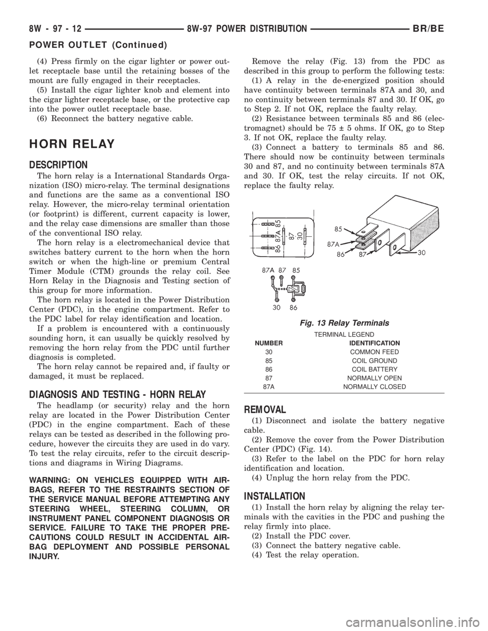
INJURY.Remove the relay (Fig. 13) from the PDC as
described in this group to perform the following tests:
(1) A relay in the de-energized position should
have continuity between terminals 87A and 30, and
no continuity between terminals 87 and 30. If OK, go
to Step 2. If not OK, replace the faulty relay.
(2) Resistance between terminals 85 and 86 (elec-
tromagnet) should be 75 5 ohms. If OK, go to Step
3. If not OK, replace the faulty relay.
(3) Connect a battery to terminals 85 and 86.
There should now be continuity between terminals
30 and 87, and no continuity between terminals 87A
and 30. If OK, test the relay circuits. If not OK,
replace the faulty relay.REMOVAL
(1) Disconnect and isolate the battery negative
cable.
(2) Remove the cover from the Power Distribution
Center (PDC) (Fig. 14).
(3) Refer to the label on the PDC for horn relay
identification and location.
(4) Unplug the horn relay from the PDC.
INSTALLATION
(1) Install the horn relay by aligning the relay ter-
minals with the cavities in the PDC and pushing the
relay firmly into place.
(2) Install the PDC cover.
(3) Connect the battery negative cable.
(4) Test the relay operation.
Fig. 13 Relay Terminals
TERMINAL LEGEND
NUMBER IDENTIFICATION
30 COMMON FEED
85 COIL GROUND
86 COIL BATTERY
87 NORMALLY OPEN
87A NORMALLY CLOSED
8W - 97 - 12 8W-97 POWER DISTRIBUTIONBR/BE
POWER OUTLET (Continued)
Page 1084 of 2255
CONDITION POSSIBLE CAUSES CORRECTION
OIL PUMPING AT RINGS; SPARK
PLUGS FOULING1. Worn or damaged rings. 1. Hone cylinder bores and replace
rings.
2. Carbon in oil ring slots. 2. Replace rings.
3. Incorrect ring size installed. 3. Replace rings.
4. Worn valve guides. 4. Ream guides and replace valves.
5. Leaking intake gasket. 5. Replace intake gaskets.
6. Leaking valve guide seals. 6. Replace valve guide seals.
DIAGNOSIS AND TESTINGÐCYLINDER
COMPRESSION PRESSURE
The results of a cylinder compression pressure test
can be utilized to diagnose several engine malfunc-
tions.
Ensure the battery is completely charged and the
engine starter motor is in good operating condition.
Otherwise, the indicated compression pressures may
not be valid for diagnosis purposes.
(1) Clean the spark plug recesses with compressed
air.
(2) Remove the spark plugs (Refer to 8 - ELEC-
TRICAL/IGNITION CONTROL/SPARK PLUG -
REMOVAL).
(3) Secure the throttle in the wide-open position.
(4) Disconnect the ignition coil.
(5) Insert a compression pressure gauge and rotate
the engine with the engine starter motor for three
revolutions.
(6) Record the compression pressure on the third
revolution. Continue the test for the remaining cylin-
ders.
(Refer to 9 - ENGINE - SPECIFICATIONS) for the
correct engine compression pressures.
DIAGNOSIS AND TESTING - CYLINDER
COMBUSTION PRESSURE LEAKAGE
The combustion pressure leakage test provides an
accurate means for determining engine condition.
Combustion pressure leakage testing will detect:
²Exhaust and intake valve leaks (improper seat-
ing)
²Leaks between adjacent cylinders or into water
jacket²Any causes for combustion/compression pressure
loss
WARNING: DO NOT REMOVE THE RADIATOR CAP
WITH THE SYSTEM HOT AND UNDER PRESSURE.
SERIOUS BURNS FROM HOT COOLANT CAN
OCCUR.
Check the coolant level and fill as required. DO
NOT install the radiator cap.
Start and operate the engine until it attains nor-
mal operating temperature, then turn OFF the
engine.
Remove the spark plugs.
Remove the oil filler cap.
Remove the air cleaner.
Calibrate the tester according to the manufactur-
er's instructions. The shop air source for testing
should maintain 483 kPa (70 psi) minimum, 1,379
kPa (200 psi) maximum and 552 kPa (80 psi) recom-
mended.
Perform the test procedure on each cylinder accord-
ing to the tester manufacturer's instructions. While
testing, listen for pressurized air escaping through
the throttle body, tailpipe or oil filler cap opening.
Check for bubbles in the radiator coolant.
All gauge pressure indications should be equal,
with no more than 25% leakage.
FOR EXAMPLE:At 552 kPa (80 psi) input pres-
sure, a minimum of 414 kPa (60 psi) should be main-
tained in the cylinder CYLINDER COMBUSTION
PRESSURE LEAKAGE DIAGNOSIS CHART .
BR/BEENGINE 5.9L 9 - 9
ENGINE 5.9L (Continued)
Page 1096 of 2255
OPERATION
OPERATIONÐCYLINDER HEAD
The cylinder head closes the combustion chamber
allowing the pistons to compress the air fuel mixture
to the correct ratio for ignition. The valves located in
the cylinder head open and close to either allow clean
air into the combustion chamber or to allow the
exhaust gases out, depending on the stroke of the
engine.
OPERATION - CYLINDER HEAD COVER
GASKET
The steel-backed silicone gasket is designed to seal
the cylinder head cover for long periods of time
through extensive heat and cold, without failure. The
gasket is designed to be reusable.
DIAGNOSIS AND TESTINGÐCYLINDER HEAD
GASKET FAILURE
A cylinder head gasket leak can be located between
adjacent cylinders or between a cylinder and the
adjacent water jacket.
²Possible indications of the cylinder head gasket
leaking between adjacent cylinders are:
²Loss of engine power
²Engine misfiring
²Poor fuel economy
²Possible indications of the cylinder head gasket
leaking between a cylinder and an adjacent water
jacket are:
²Engine overheating
²Loss of coolant
²Excessive steam (white smoke) emitting from
exhaust
²Coolant foaming
CYLINDER-TO-CYLINDER LEAKAGE TEST
To determine if an engine cylinder head gasket is
leaking between adjacent cylinders, follow the proce-
dures in Cylinder Compression Pressure Test in this
section. An engine cylinder head gasket leaking
between adjacent cylinders will result in approxi-
mately a 50±70% reduction in compression pressure.
CYLINDER-TO-WATER JACKET LEAKAGE TEST
WARNING: USE EXTREME CAUTION WHEN THE
ENGINE IS OPERATING WITH COOLANT PRES-
SURE CAP REMOVED.
VISUAL TEST METHOD
With the engine cool, remove the coolant pressure
cap. Start the engine and allow it to warm up until
thermostat opens.If a large combustion/compression pressure leak
exists, bubbles will be visible in the coolant.
COOLING SYSTEM TESTER METHOD
WARNING: WITH COOLING SYSTEM TESTER IN
PLACE, PRESSURE WILL BUILD UP FAST. EXCES-
SIVE PRESSURE BUILT UP, BY CONTINUOUS
ENGINE OPERATION, MUST BE RELEASED TO A
SAFE PRESSURE POINT. NEVER PERMIT PRES-
SURE TO EXCEED 138 kPa (20 psi).
Install Cooling System Tester 7700 or equivalent to
pressure cap neck. Start the engine and observe the
tester's pressure gauge. If gauge pulsates with every
power stroke of a cylinder a combustion pressure
leak is evident.
CHEMICAL TEST METHOD
Combustion leaks into the cooling system can also
be checked by using Bloc-Chek Kit C-3685-A or
equivalent. Perform test following the procedures
supplied with the tool kit.
REMOVAL
(1) Disconnect the battery negative cable.
(2) Drain cooling system (Refer to 7 - COOLING -
STANDARD PROCEDURE).
(3) Remove the air cleaner resonator and duct
work.
(4) Remove the intake manifold-to-generator
bracket support rod. Remove the generator.
(5) Remove closed crankcase ventilation system.
(6) Disconnect the evaporation control system.
(7) Perform the Fuel System Pressure Release pro-
cedure (Refer to 14 - FUEL SYSTEM/FUEL DELIV-
ERY - STANDARD PROCEDURE). Disconnect the
fuel supply line (Refer to 14 - FUEL SYSTEM/FUEL
DELIVERY/QUICK CONNECT FITTING - STAN-
DARD PROCEDURE).
(8) Disconnect accelerator linkage and if so
equipped, the speed control and transmission kick-
down cables.
(9) Remove distributor cap and wires.
(10) Disconnect the coil wires.
(11) Disconnect heat indicator sending unit wire.
(12) Disconnect heater hoses and bypass hose.
(13) Remove cylinder head covers and gaskets
(Refer to 9 - ENGINE/CYLINDER HEAD/CYLIN-
DER HEAD COVER(S) - REMOVAL).
(14) Remove intake manifold (Refer to 9 -
ENGINE/MANIFOLDS/INTAKE MANIFOLD -
REMOVAL) and throttle body as an assembly. Dis-
card the flange side gaskets and the front and rear
cross-over gaskets.
BR/BEENGINE 5.9L 9 - 21
CYLINDER HEAD (Continued)