2002 DODGE RAM seat adjustment
[x] Cancel search: seat adjustmentPage 63 of 2255
CENTER BEARING
REMOVAL
(1) Remove rear propeller shaft.
(2) Remove slip joint boot clamp and separate the
two half-shafts.
(3) Use hammer and punch to tap slinger away
from shaft to provide room for bearing splitter.
(4) Position Bearing Splitter Tool 1130 between
slinger and shaft.
CAUTION: Do not damage shaft spline during
removal of center bearing.
(5)
Set shaft in press and press bearing off the shaft.
INSTALLATION
NOTE: Two types of center bearings are used and
are not interchangeable. Install the same type as
the vehicle was built with.
(1) Install new slinger on shaft and drive into posi-
tion with appropriate installer tool.
(2) Install new center bearing on shaft with Bear-
ing Installer Tool 6052. Drive on shaft with hammer
until bearing is seated.
(3) Clean shaft splines and apply a coat of multi-
purpose grease.
(4) Align master splines and slide front and rear
half-shafts together. Reposition slip yoke boot and
install new clamp.
(5) Install propeller shaft in vehicle.
ADJUSTMENTS
ADJUSTMENT - CENTER BEARING
Launch shudder is a vibration that occurs at first
acceleration from a stop. Shudder vibration usually
peaks at the engines highest torque output. Shudder is
a symptom associated with vehicles using a two-piece
propeller shaft. To decrease shudder, lower the center
bearing in 1/8 inch increments. Use shim stock or fab-
ricated plates. Plate stock must be used to maintain
compression of the rubber insulator around the bearing.
Do not use washers. Replace the original bolts with the
appropriate increased length bolts.
SINGLE CARDAN UNIVERSAL
JOINTS
DISASSEMBLY
Individual components of cardan universal joints
are not serviceable. If worn or leaking, they must be
replaced as an assembly.
(1) Remove the propeller shaft.
(2) With a soft drift, tap the outside of the bearing
cap assembly to loosen snap ring.
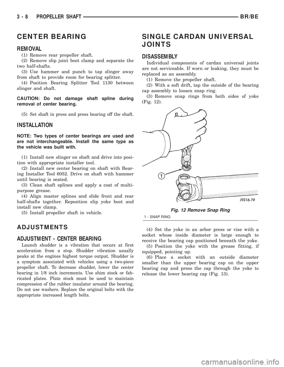
(3) Remove snap rings from both sides of yoke
(Fig. 12).
(4) Set the yoke in an arbor press or vise with a
socket whose inside diameter is large enough to
receive the bearing cap positioned beneath the yoke.
(5) Position the yoke with the grease fitting, if
equipped, pointing up.
(6) Place a socket with an outside diameter
smaller than the upper bearing cap on the upper
bearing cap and press the cap through the yoke to
release the lower bearing cap (Fig. 13).
Fig. 12 Remove Snap Ring
1 - SNAP RING
3 - 8 PROPELLER SHAFTBR/BE
Page 94 of 2255

INSTALLATION
NOTE: If replacement differential bearings or differ-
ential case are being installed, differential side
bearing shim requirements may change. Refer to
Adjustments (Differential Bearing Preload and Gear
Backlash) procedures to determine proper shim
selection.
(1) Position Spreader W-129-B with the tool dowel
pins seated in the locating holes. Install the hold
down clamps and tighten the tool turnbuckle finger-
tight.
(2) Install a Pilot Stud C-3288-B at the left side of
the differential housing and attach dial indicator to
the pilot stud. Load the indicator plunger against the
opposite side of the housing and zero the dial indica-
tor.
(3) Spread the housing enough to install the case
in the housing. Measure the distance with the dial
indicator.
CAUTION: Never spread the housing over 0.50 mm
(0.020 in). If housing is over-spread, it could be dis-
torted or damaged.
(4) Remove the dial indicator.(5) Install differential into the housing. Tap the
differential case with a rawhide/rubber hammer to
ensure the bearings are seated in housing (Fig. 42).
(6) Remove the spreader.
(7) Install bearing caps in their original locations
(Fig. 43) and tighten bearing cap bolts in a criss-
cross pattern to 109 N´m (80 ft. lbs.).
(8) Install axle shafts.
(9) Install the hub bearings.
Fig. 41 Pinion Mate Shaft Roll-Pin
1 - PUNCH
2 - PINION MATE SHAFT
3 - MATE SHAFT LOCKPIN
Fig. 42 DIFFERENTIAL CASE
1 - RAWHIDE HAMMER
Fig. 43 Bearing Cap Reference
1 - REFERENCE LETTERS
2 - REFERENCE LETTERS
BR/BEFRONT AXLE - 248FBI 3 - 39
DIFFERENTIAL (Continued)
Page 98 of 2255
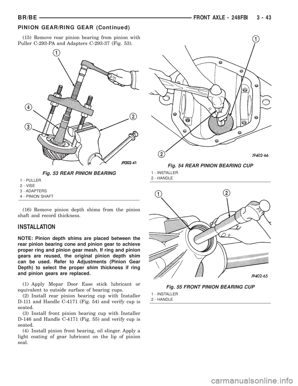
(15) Remove rear pinion bearing from pinion with
Puller C-293-PA and Adapters C-293-37 (Fig. 53).
(16) Remove pinion depth shims from the pinion
shaft and record thickness.
INSTALLATION
NOTE: Pinion depth shims are placed between the
rear pinion bearing cone and pinion gear to achieve
proper ring and pinion gear mesh. If ring and pinion
gears are reused, the original pinion depth shim
can be used. Refer to Adjustments (Pinion Gear
Depth) to select the proper shim thickness if ring
and pinion gears are replaced.
(1) Apply Mopar Door Ease stick lubricant or
equivalent to outside surface of bearing cups.
(2) Install rear pinion bearing cup with Installer
D-111 and Handle C-4171 (Fig. 54) and verify cup is
seated.
(3) Install front pinion bearing cup with Installer
D-146 and Handle C-4171 (Fig. 55) and verify cup is
seated.
(4) Install pinion front bearing, oil slinger. Apply a
light coating of gear lubricant on the lip of pinion
seal.
Fig. 53 REAR PINION BEARING
1 - PULLER
2 - VISE
3 - ADAPTERS
4 - PINION SHAFT
Fig. 54 REAR PINION BEARING CUP
1 - INSTALLER
2 - HANDLE
Fig. 55 FRONT PINION BEARING CUP
1 - INSTALLER
2 - HANDLE
BR/BEFRONT AXLE - 248FBI 3 - 43
PINION GEAR/RING GEAR (Continued)
Page 121 of 2255

(4) Remove the differential side gears and thrust
washers.
ASSEMBLY
(1) Install the differential side gears and thrust
washers.
(2) Install the pinion mate gears and thrust wash-
ers.
(3) Install the pinion gear mate shaft.
(4) Align the hole in the pinion gear mate shaft
with the hole in the differential case.
(5) Install and seat the pinion mate shaft roll-pin
in the differential case and mate shaft with a punch
and hammer (Fig. 32). Peen the edge of the roll-pin
hole in the differential case slightly in two places,
180É apart.
(6) Lubricate all differential components with
hypoid gear lubricant.
INSTALLATION
NOTE: If replacement differential bearings or differ-
ential case are being installed, differential side
bearing shim requirements may change. Refer to
Adjustments (Differential Bearing Preload and Gear
Backlash) procedures to determine proper shim
selection.(1) Position Spreader W-129-B with the tool dowel
pins seated in the locating holes. Install the hold
down clamps and tighten the tool turnbuckle finger-
tight.
(2) Install a Pilot Stud C-3288-B at the left side of
the differential housing and attach dial indicator to
the pilot stud. Load the indicator plunger against the
opposite side of the housing and zero the dial indica-
tor.
(3) Spread the housing enough to install the case
in the housing. Measure the distance with the dial
indicator.
CAUTION: Never spread the housing over 0.50 mm
(0.020 in). If housing is over-spread, it could be dis-
torted or damaged.
(4) Remove the dial indicator.
(5) Install differential into the housing. Tap the
differential case with a rawhide/rubber hammer to
ensure the bearings are seated in housing (Fig. 33).
(6) Remove the spreader.
(7) Install bearing caps in their original locations
(Fig. 34) and tighten bearing cap bolts in a criss-
cross pattern to 109 N´m (80 ft. lbs.).
(8) Install axle shafts.
(9) Install the hub bearings.
(10) Apply a bead of red Mopar Silicone Rubber
Sealant or equivalent to the housing cover (Fig. 35).
Fig. 31 PINION MATE/SIDE GEAR
1 - THRUST WASHER
2 - SIDE GEAR
3 - PINION MATE GEARFig. 32 PINION MATE SHAFT ROLL-PIN
1 - PUNCH
2 - PINION MATE SHAFT
3 - MATE SHAFT LOCKPIN
3 - 66 REAR AXLE - 248RBIBR/BE
DIFFERENTIAL (Continued)
Page 130 of 2255
INSTALLATION
(1) Apply Mopar Door Ease stick or equivalent
lubricant to outside surface of bearing cups.
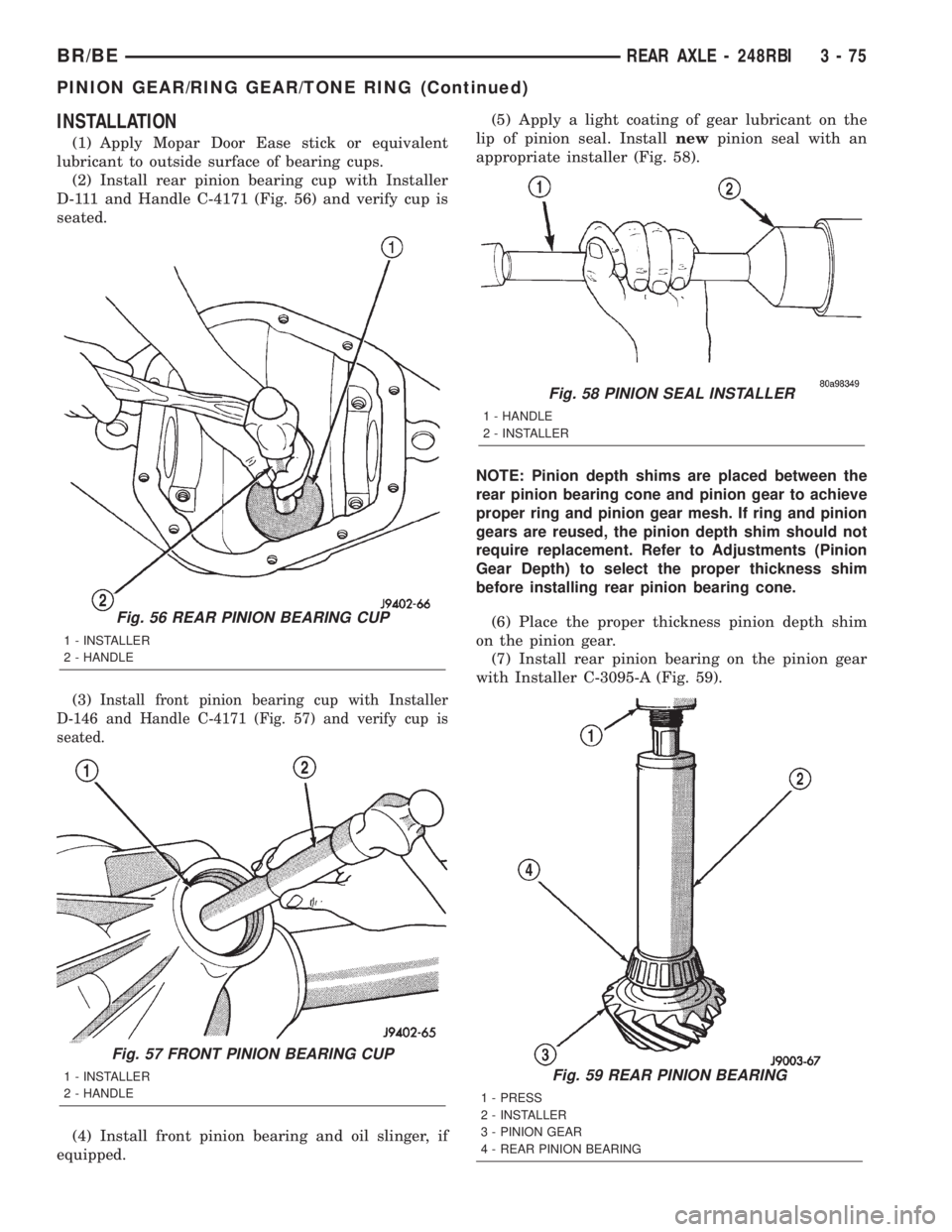
(2) Install rear pinion bearing cup with Installer
D-111 and Handle C-4171 (Fig. 56) and verify cup is
seated.
(3)
Install front pinion bearing cup with Installer
D-146 and Handle C-4171 (Fig. 57) and verify cup is
seated.
(4) Install front pinion bearing and oil slinger, if
equipped.(5) Apply a light coating of gear lubricant on the
lip of pinion seal. Installnewpinion seal with an
appropriate installer (Fig. 58).
NOTE: Pinion depth shims are placed between the
rear pinion bearing cone and pinion gear to achieve
proper ring and pinion gear mesh. If ring and pinion
gears are reused, the pinion depth shim should not
require replacement. Refer to Adjustments (Pinion
Gear Depth) to select the proper thickness shim
before installing rear pinion bearing cone.
(6) Place the proper thickness pinion depth shim
on the pinion gear.
(7) Install rear pinion bearing on the pinion gear
with Installer C-3095-A (Fig. 59).
Fig. 59 REAR PINION BEARING
1 - PRESS
2 - INSTALLER
3 - PINION GEAR
4 - REAR PINION BEARING
Fig. 56 REAR PINION BEARING CUP
1 - INSTALLER
2 - HANDLE
Fig. 57 FRONT PINION BEARING CUP
1 - INSTALLER
2 - HANDLE
Fig. 58 PINION SEAL INSTALLER
1 - HANDLE
2 - INSTALLER
BR/BEREAR AXLE - 248RBI 3 - 75
PINION GEAR/RING GEAR/TONE RING (Continued)
Page 152 of 2255
DISASSEMBLY
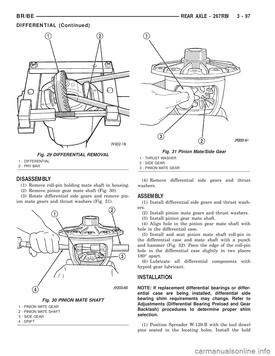
(1) Remove roll-pin holding mate shaft in housing.
(2) Remove pinion gear mate shaft (Fig. 30).
(3) Rotate differential side gears and remove pin-
ion mate gears and thrust washers (Fig. 31).(4) Remove differential side gears and thrust
washers.
ASSEMBLY
(1) Install differential side gears and thrust wash-
ers.
(2) Install pinion mate gears and thrust washers.
(3) Install pinion gear mate shaft.
(4) Align hole in the pinion gear mate shaft with
hole in the differential case.
(5) Install and seat pinion mate shaft roll-pin in
the differential case and mate shaft with a punch
and hammer (Fig. 32). Peen the edge of the roll-pin
hole in the differential case slightly in two places
180É apart.
(6) Lubricate all differential components with
hypoid gear lubricant.
INSTALLATION
NOTE: If replacement differential bearings or differ-
ential case are being installed, differential side
bearing shim requirements may change. Refer to
Adjustments (Differential Bearing Preload and Gear
Backlash) procedures to determine proper shim
selection.
(1) Position Spreader W-129-B with the tool dowel
pins seated in the locating holes. Install the hold
Fig. 29 DIFFERENTIAL REMOVAL
1 - DIFFERENTIAL
2-PRYBAR
Fig. 30 PINION MATE SHAFT
1 - PINION MATE GEAR
2 - PINION MATE SHAFT
3 - SIDE GEAR
4 - DRIFT
Fig. 31 Pinion Mate/Side Gear
1 - THRUST WASHER
2 - SIDE GEAR
3 - PINION MATE GEAR
BR/BEREAR AXLE - 267RBI 3 - 97
DIFFERENTIAL (Continued)
Page 160 of 2255
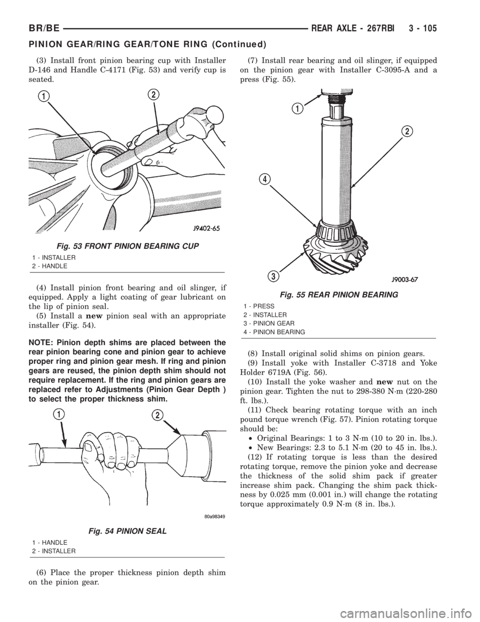
(3) Install front pinion bearing cup with Installer
D-146 and Handle C-4171 (Fig. 53) and verify cup is
seated.
(4) Install pinion front bearing and oil slinger, if
equipped. Apply a light coating of gear lubricant on
the lip of pinion seal.
(5) Install anewpinion seal with an appropriate
installer (Fig. 54).
NOTE: Pinion depth shims are placed between the
rear pinion bearing cone and pinion gear to achieve
proper ring and pinion gear mesh. If ring and pinion
gears are reused, the pinion depth shim should not
require replacement. If the ring and pinion gears are
replaced refer to Adjustments (Pinion Gear Depth )
to select the proper thickness shim.
(6) Place the proper thickness pinion depth shim
on the pinion gear.(7) Install rear bearing and oil slinger, if equipped
on the pinion gear with Installer C-3095-A and a
press (Fig. 55).
(8) Install original solid shims on pinion gears.
(9) Install yoke with Installer C-3718 and Yoke
Holder 6719A (Fig. 56).
(10) Install the yoke washer andnewnut on the
pinion gear. Tighten the nut to 298-380 N´m (220-280
ft. lbs.).
(11) Check bearing rotating torque with an inch
pound torque wrench (Fig. 57). Pinion rotating torque
should be:
²Original Bearings: 1 to 3 N´m (10 to 20 in. lbs.).
²New Bearings: 2.3 to 5.1 N´m (20 to 45 in. lbs.).
(12) If rotating torque is less than the desired
rotating torque, remove the pinion yoke and decrease
the thickness of the solid shim pack if greater
increase shim pack. Changing the shim pack thick-
ness by 0.025 mm (0.001 in.) will change the rotating
torque approximately 0.9 N´m (8 in. lbs.).
Fig. 53 FRONT PINION BEARING CUP
1 - INSTALLER
2 - HANDLE
Fig. 54 PINION SEAL
1 - HANDLE
2 - INSTALLER
Fig. 55 REAR PINION BEARING
1 - PRESS
2 - INSTALLER
3 - PINION GEAR
4 - PINION BEARING
BR/BEREAR AXLE - 267RBI 3 - 105
PINION GEAR/RING GEAR/TONE RING (Continued)
Page 181 of 2255
(14) Remove the case from housing. Tag bearing
cups to indicate their location.
DISASSEMBLY
(1) Remove roll-pin holding mate shaft in housing.
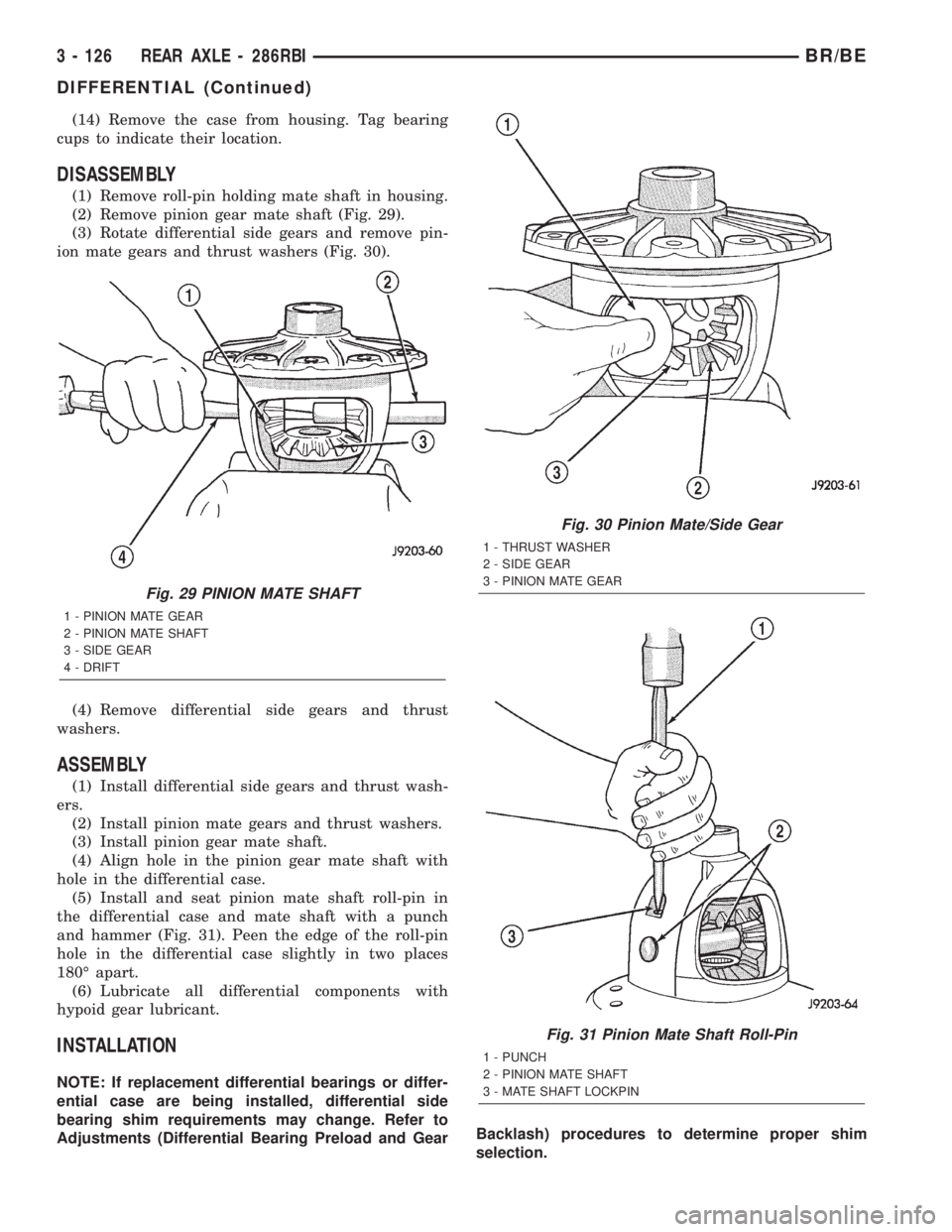
(2) Remove pinion gear mate shaft (Fig. 29).
(3) Rotate differential side gears and remove pin-
ion mate gears and thrust washers (Fig. 30).
(4) Remove differential side gears and thrust
washers.
ASSEMBLY
(1) Install differential side gears and thrust wash-
ers.
(2) Install pinion mate gears and thrust washers.
(3) Install pinion gear mate shaft.
(4) Align hole in the pinion gear mate shaft with
hole in the differential case.
(5) Install and seat pinion mate shaft roll-pin in
the differential case and mate shaft with a punch
and hammer (Fig. 31). Peen the edge of the roll-pin
hole in the differential case slightly in two places
180É apart.
(6) Lubricate all differential components with
hypoid gear lubricant.
INSTALLATION
NOTE: If replacement differential bearings or differ-
ential case are being installed, differential side
bearing shim requirements may change. Refer to
Adjustments (Differential Bearing Preload and GearBacklash) procedures to determine proper shim
selection.
Fig. 29 PINION MATE SHAFT
1 - PINION MATE GEAR
2 - PINION MATE SHAFT
3 - SIDE GEAR
4 - DRIFT
Fig. 30 Pinion Mate/Side Gear
1 - THRUST WASHER
2 - SIDE GEAR
3 - PINION MATE GEAR
Fig. 31 Pinion Mate Shaft Roll-Pin
1 - PUNCH
2 - PINION MATE SHAFT
3 - MATE SHAFT LOCKPIN
3 - 126 REAR AXLE - 286RBIBR/BE
DIFFERENTIAL (Continued)