2002 DODGE RAM seat adjustment
[x] Cancel search: seat adjustmentPage 1223 of 2255
INSTALLATION
(1) If previously removed, install the push rods in
their original location (Fig. 62).Verify that they
are seated in the tappets.
(2) Lubricate the valve tips and install the cross-
heads in their original locations.
(3) Lubricate the crossheads and push rod sockets
and install the rocker arms and pedestals (Fig. 60) in
their original locations. Tighten bolts to 36 N´m (27
ft. lbs.) torque.
(4)Verify valve lash adjustment (Refer to 9 -
ENGINE/CYLINDER HEAD/INTAKE/EXHAUST
VALVES & SEATS - STANDARD PROCEDURE).
(5) Install cylinder head cover and reusable gasket
(Fig. 59) (Refer to 9 - ENGINE/CYLINDER HEAD/
CYLINDER HEAD COVER(S) - INSTALLATION).
(6) Connect battery negative cables.
ENGINE BLOCK
STANDARD PROCEDURE
STANDARD PROCEDURE - CYLINDER BLOCK
REFACING
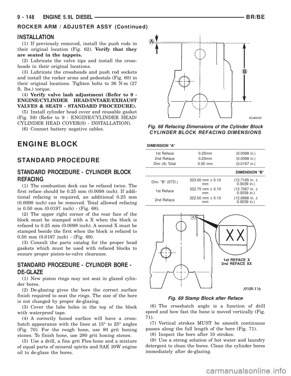
(1) The combustion deck can be refaced twice. The
first reface should be 0.25 mm (0.0098 inch). If addi-
tional refacing is required, an additional 0.25 mm
(0.0098 inch) can be removed. Total allowed refacing
is 0.50 mm (0.0197 inch) - (Fig. 68).
(2) The upper right corner of the rear face of the
block must be stamped with a X when the block is
refaced to 0.25 mm (0.0098 inch). A second X must be
stamped beside the first when the block is refaced to
0.50 mm (0.0197 inch) - (Fig. 69).
(3) Consult the parts catalog for the proper head
gaskets which must be used with refaced blocks to
ensure proper piston-to-valve clearance.
STANDARD PROCEDURE - CYLINDER BORE -
DE-GLAZE
(1) New piston rings may not seat in glazed cylin-
der bores.
(2) De-glazing gives the bore the correct surface
finish required to seat the rings. The size of the bore
is not changed by proper de-glazing.
(3) Cover the lube holes in the top of the block
with waterproof tape.
(4) A correctly honed surface will have a cross-
hatch appearance with the lines at 15É to 25É angles
(Fig. 70). For the rough hone, use 80 grit honing
stones. To finish hone, use 280 grit honing stones.
(5) Use a drill, a fine grit Flex-hone and a mixture
of equal parts of mineral spirits and SAE 30W engine
oil to de-glaze the bores.(6) The crosshatch angle is a function of drill
speed and how fast the hone is moved vertically (Fig.
71).
(7) Vertical strokes MUST be smooth continuous
passes along the full length of the bore (Fig. 71).
(8) Inspect the bore after 10 strokes.
(9) Use a strong solution of hot water and laundry
detergent to clean the bores. Clean the cylinder bores
immediately after de-glazing.
Fig. 68 Refacing Dimensions of the Cylinder Block
CYLINDER BLOCK REFACING DIMENSIONS
DIMENSION(A(
1st Reface 0.25mm (0.0098 in.)
2nd Reface 0.25mm (0.0098 in.)
Dim (A) Total 0.50 mm (0.0197 in.)
DIMENSION(B(
Dim.9B9(STD.)323.00 mm 0.10
mm(12.7165 in.
0.0039 in.)
1st Reface322.75 mm 0.10
mm(12.7067 in.
0.0039 in.)
2nd Reface322.50 mm 0.10
mm(12.6968 in.
0.0039 in.)
Fig. 69 Stamp Block after Reface
9 - 148 ENGINE 5.9L DIESELBR/BE
ROCKER ARM / ADJUSTER ASSY (Continued)
Page 1232 of 2255
Thrust Plate
Inspect the camshaft thrust plate for excessive
wear in the camshaft contact area. Measure thrust
plate thickness using the CAMSHAFT THRUST
PLATE THICKNESS CHART . Replace any thrust
plate that falls outside of these specifications:
CAMSHAFT THRUST PLATE THICKNESS CHART
9.34 mm (0.368 in.) MIN.
9.58 mm (0.377 in.) MAX.
INSTALLATION
INSTALLATIONÐCAMSHAFT BEARINGS
(1) Apply a coating of Loctitet640 Adhesive to the
backside of the new bushing. Avoid getting adhesive
in the oil hole.
(2) Use a universal cam bushing installation tool
and install the bushing so that it is even with the
front face of the cylinder block. The oil hole must be
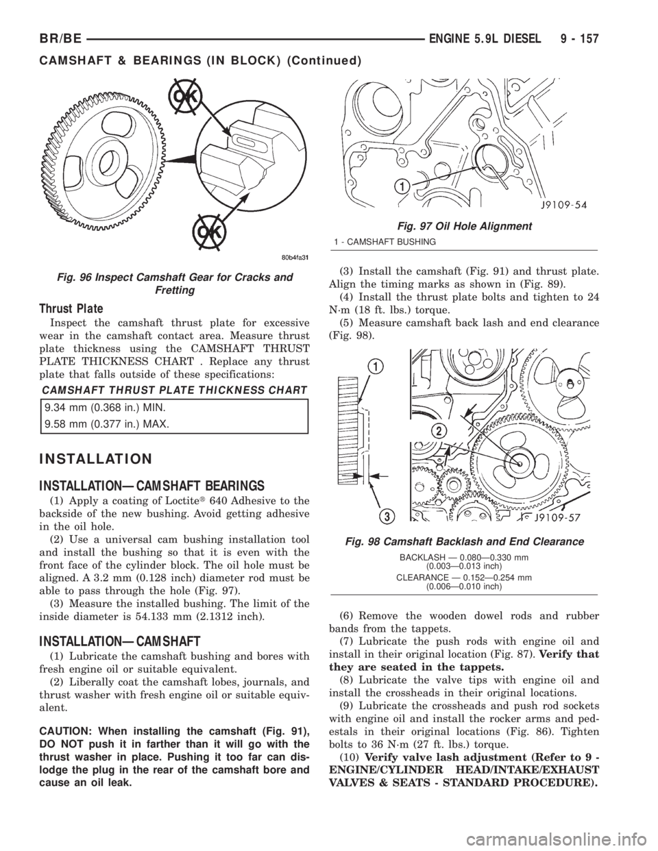
aligned. A 3.2 mm (0.128 inch) diameter rod must be
able to pass through the hole (Fig. 97).
(3) Measure the installed bushing. The limit of the
inside diameter is 54.133 mm (2.1312 inch).
INSTALLATIONÐCAMSHAFT
(1) Lubricate the camshaft bushing and bores with
fresh engine oil or suitable equivalent.
(2) Liberally coat the camshaft lobes, journals, and
thrust washer with fresh engine oil or suitable equiv-
alent.
CAUTION: When installing the camshaft (Fig. 91),
DO NOT push it in farther than it will go with the
thrust washer in place. Pushing it too far can dis-
lodge the plug in the rear of the camshaft bore and
cause an oil leak.(3) Install the camshaft (Fig. 91) and thrust plate.
Align the timing marks as shown in (Fig. 89).
(4) Install the thrust plate bolts and tighten to 24
N´m (18 ft. lbs.) torque.
(5) Measure camshaft back lash and end clearance
(Fig. 98).
(6) Remove the wooden dowel rods and rubber
bands from the tappets.
(7) Lubricate the push rods with engine oil and
install in their original location (Fig. 87).Verify that
they are seated in the tappets.
(8) Lubricate the valve tips with engine oil and
install the crossheads in their original locations.
(9) Lubricate the crossheads and push rod sockets
with engine oil and install the rocker arms and ped-
estals in their original locations (Fig. 86). Tighten
bolts to 36 N´m (27 ft. lbs.) torque.
(10)Verify valve lash adjustment (Refer to 9 -
ENGINE/CYLINDER HEAD/INTAKE/EXHAUST
VALVES & SEATS - STANDARD PROCEDURE).
Fig. 96 Inspect Camshaft Gear for Cracks and
Fretting
Fig. 97 Oil Hole Alignment
1 - CAMSHAFT BUSHING
Fig. 98 Camshaft Backlash and End Clearance
BACKLASH Ð 0.080Ð0.330 mm
(0.003Ð0.013 inch)
CLEARANCE Ð 0.152Ð0.254 mm
(0.006Ð0.010 inch)
BR/BEENGINE 5.9L DIESEL 9 - 157
CAMSHAFT & BEARINGS (IN BLOCK) (Continued)
Page 1418 of 2255
(3) Remove the shipping lock pin if necessary.
(4) Install the column through the floor pan.
(5) Position the column bracket breakaway cap-
sules on the mounting studs. Install, butloose
assemblethe two upper bracket nuts.
(6) With the front wheels in the straight-ahead
position. Align steering column shaft to the coupler.
Install anewpinch bolt and tighten to 49 N´m (36
ft. lbs.).
(7) Clip the wiring harness on the steering column.
Connect the multi- function switch wiring and
tighten with 7mm socket.
(8) Install the upper fixed shroud.
(9) Be sure both breakaway capsules are fully
seated in the slots in the column support bracket.
Pull the column rearward then tighten upper bracket
nuts to 12 N´m (105 in. lbs.).
(10) Tighten the toe plate to floor pan attaching
nuts to 22.5 N´m (200 in. lbs.).
(11) Install the wiring connections to the column.
Install the lower fixed shroud.
(12) Column shift vehicles, install the PRNDL
driver cable. Place shifter in Park position. If indica-tor needs adjusting, turn thumb screw on cable
retainer to adjust cable.
(13) Install the lock housing shrouds. Install the
tilt lever (if equipped).
(14) Install the knee blocker and steering column
opening cover, (Refer to 23 - BODY/INSTRUMENT
PANEL/STEERING COLUMN OPENING COVER -
INSTALLATION).
(15) Install steering wheel and tighten nut to 61
N´m (45 ft. lbs.), (Refer to 19 - STEERING/COL-
UMN/STEERING WHEEL - INSTALLATION).
(16) Install the airbag, (Refer to 8 - ELECTRICAL/
RESTRAINTS/DRIVER AIRBAG - INSTALLATION).
(17) Column shift vehicles, connect the shift link
rod to the transmission shift lever. Use multi-purpose
lubricant, or an equivalent product, to aid the instal-
lation.
(18) Install the battery ground (negative) cable.
(19) Verify operation of the automatic transmission
shift linkage and adjust as necessary, (Refer to 21 -
TRANSMISSION/TRANSAXLE/AUTOMATIC -
44RE/GEAR SHIFT CABLE - ADJUSTMENTS).
SPECIFICATIONS
TORQUE CHART
TORQUE SPECIFICATIONS
DESCRIPTION N´m Ft. Lbs. In. Lbs.
Steering Wheel
Nut61 45 Ð
Steering Coupler
Bolt49 36 Ð
Steering Column
Upper Bracket12 Ð 105
Steering Column
Toe Plate23 Ð 200
KEY-IN IGNITION SWITCH
DESCRIPTION
The key-in ignition switch is integral to the igni-
tion switch, which is mounted on the left side of the
steering column. It closes a path to ground for the
Central Timer Module (CTM) when the ignition key
is inserted in the ignition lock cylinder and the
driver door ajar switch is closed (driver door is open).
The key-in ignition switch opens the ground path
when the key is removed from the ignition lock cyl-
inder. The ground path is also opened when the
driver door ajar switch is open (driver door is closed).The key-in ignition switch cannot be repaired and,
if faulty or damaged, the entire ignition switch must
be replaced, (Refer to 19 - STEERING/COLUMN/IG-
NITION SWITCH - REMOVAL).
DIAGNOSIS AND TESTING - IGNITION SWITCH
AND KEY LOCK CYLINDER
ELECTRICAL DIAGNOSIS
For ignition switch electrical schematics, refer to
Ignition Switch in the appropriate section of Electri-
cal Wiring Diagrams.
BR/BECOLUMN 19 - 9
COLUMN (Continued)
Page 1434 of 2255
INSTALLATION
(1) Install pitman shaft bearing into housing with
a bearing driver and handle.
(2) Coat the oil seal and washer withspecial
greasesupplied with the new seal.
(3) Install the oil seal with a driver and handle.
(4) Install backup washer.
(5) Install the retainer ring with snap ring pliers.
(6) Coat the dust seal withspecial greasesup-
plied with the new seal.
(7) Install dust seal with a driver and handle.
(8) Install pitman shaft to side cover by screwing
shaft in until it fully seats to side cover.
(9) Install preload adjuster nut.Do not tighten
nut until after Over-Center Rotation Torque
adjustment has been made.
(10) Install gasket to side cover and bend tabs
around edges of side cover (Fig. 11).
(11) Install pitman shaft assembly and side cover
to housing.
(12) Install side cover bolts and tighten to 60 N´m
(44 ft. lbs.).
(13) Perform over-center rotation torque adjust-
ment, (Refer to 19 - STEERING/GEAR - ADJUST-
MENTS).
PITMAN SHAFT SEAL
REMOVAL
(1) Clean exposed end of pitman shaft and housing
with a wire brush.
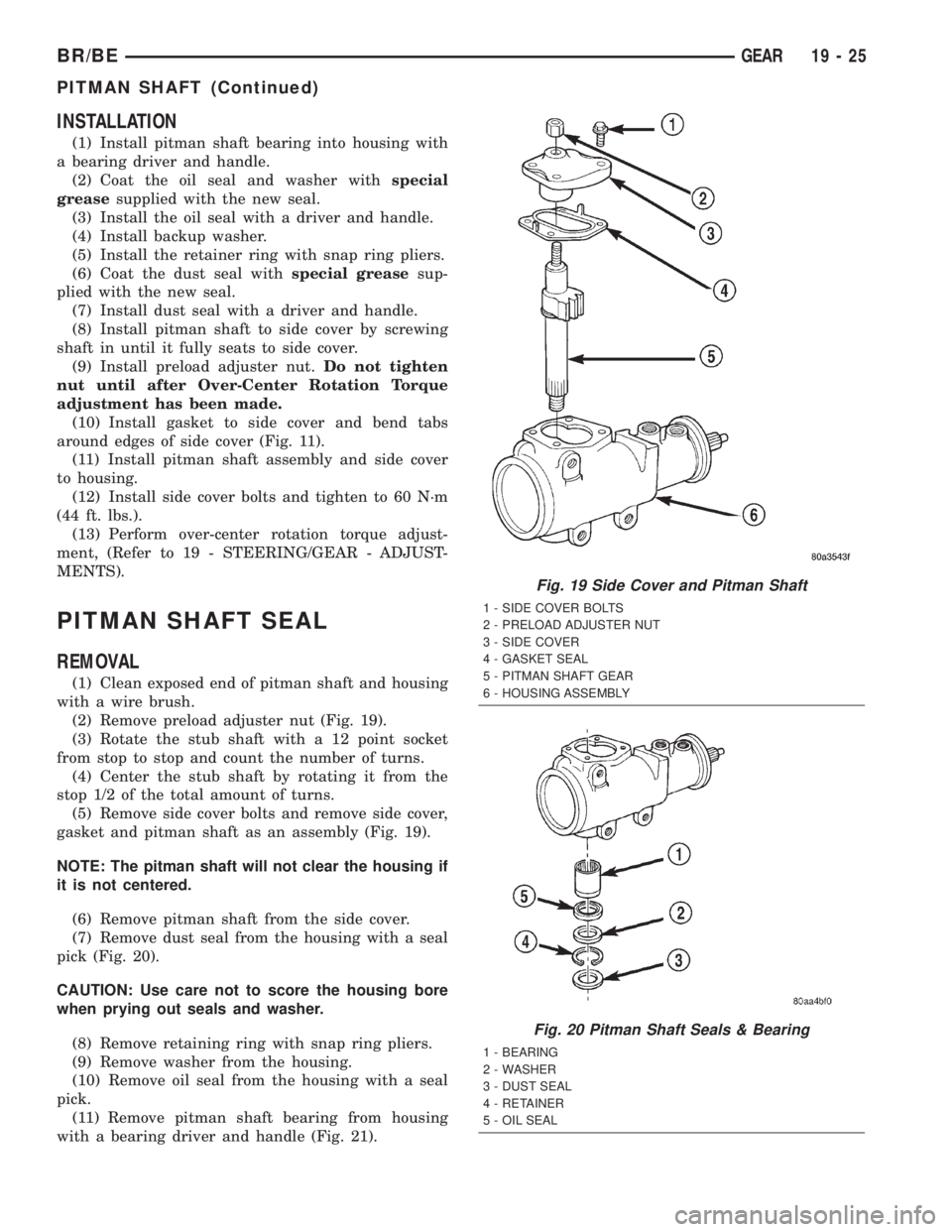
(2) Remove preload adjuster nut (Fig. 19).
(3) Rotate the stub shaft with a 12 point socket
from stop to stop and count the number of turns.
(4) Center the stub shaft by rotating it from the
stop 1/2 of the total amount of turns.
(5) Remove side cover bolts and remove side cover,
gasket and pitman shaft as an assembly (Fig. 19).
NOTE: The pitman shaft will not clear the housing if
it is not centered.
(6) Remove pitman shaft from the side cover.
(7) Remove dust seal from the housing with a seal
pick (Fig. 20).
CAUTION: Use care not to score the housing bore
when prying out seals and washer.
(8) Remove retaining ring with snap ring pliers.
(9) Remove washer from the housing.
(10) Remove oil seal from the housing with a seal
pick.
(11) Remove pitman shaft bearing from housing
with a bearing driver and handle (Fig. 21).
Fig. 19 Side Cover and Pitman Shaft
1 - SIDE COVER BOLTS
2 - PRELOAD ADJUSTER NUT
3 - SIDE COVER
4 - GASKET SEAL
5 - PITMAN SHAFT GEAR
6 - HOUSING ASSEMBLY
Fig. 20 Pitman Shaft Seals & Bearing
1 - BEARING
2 - WASHER
3 - DUST SEAL
4 - RETAINER
5 - OIL SEAL
BR/BEGEAR 19 - 25
PITMAN SHAFT (Continued)
Page 1438 of 2255
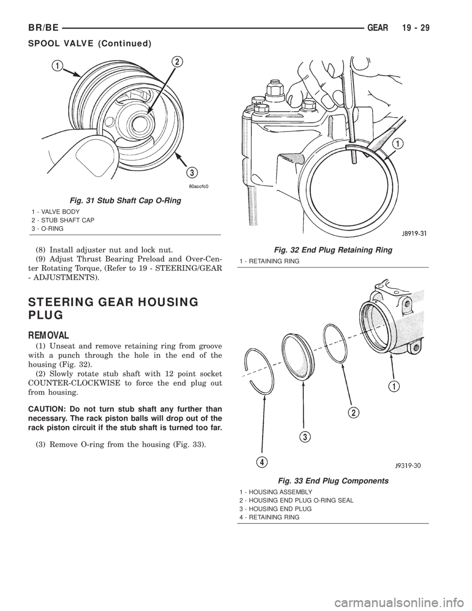
(8) Install adjuster nut and lock nut.
(9) Adjust Thrust Bearing Preload and Over-Cen-
ter Rotating Torque, (Refer to 19 - STEERING/GEAR
- ADJUSTMENTS).
STEERING GEAR HOUSING
PLUG
REMOVAL
(1) Unseat and remove retaining ring from groove
with a punch through the hole in the end of the
housing (Fig. 32).
(2) Slowly rotate stub shaft with 12 point socket
COUNTER-CLOCKWISE to force the end plug out
from housing.
CAUTION: Do not turn stub shaft any further than
necessary. The rack piston balls will drop out of the
rack piston circuit if the stub shaft is turned too far.
(3) Remove O-ring from the housing (Fig. 33).
Fig. 31 Stub Shaft Cap O-Ring
1 - VALVE BODY
2 - STUB SHAFT CAP
3 - O-RING
Fig. 32 End Plug Retaining Ring
1 - RETAINING RING
Fig. 33 End Plug Components
1 - HOUSING ASSEMBLY
2 - HOUSING END PLUG O-RING SEAL
3 - HOUSING END PLUG
4 - RETAINING RING
BR/BEGEAR 19 - 29
SPOOL VALVE (Continued)
Page 1441 of 2255
CAUTION: The rack piston balls must be installed
alternately into the rack piston and ball guide. This
maintains worm shaft preload. There are 12 black
balls and 12 silver (Chrome) balls. The black balls
are smaller than the silver balls.
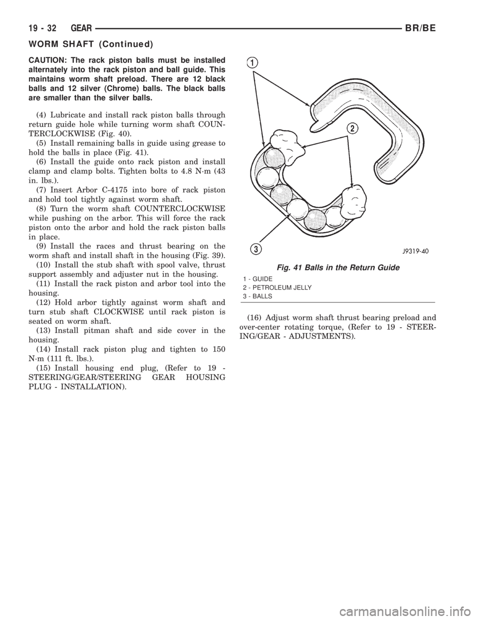
(4) Lubricate and install rack piston balls through
return guide hole while turning worm shaft COUN-
TERCLOCKWISE (Fig. 40).
(5) Install remaining balls in guide using grease to
hold the balls in place (Fig. 41).
(6) Install the guide onto rack piston and install
clamp and clamp bolts. Tighten bolts to 4.8 N´m (43
in. lbs.).
(7) Insert Arbor C-4175 into bore of rack piston
and hold tool tightly against worm shaft.
(8) Turn the worm shaft COUNTERCLOCKWISE
while pushing on the arbor. This will force the rack
piston onto the arbor and hold the rack piston balls
in place.
(9) Install the races and thrust bearing on the
worm shaft and install shaft in the housing (Fig. 39).
(10) Install the stub shaft with spool valve, thrust
support assembly and adjuster nut in the housing.
(11) Install the rack piston and arbor tool into the
housing.
(12) Hold arbor tightly against worm shaft and
turn stub shaft CLOCKWISE until rack piston is
seated on worm shaft.
(13) Install pitman shaft and side cover in the
housing.
(14) Install rack piston plug and tighten to 150
N´m (111 ft. lbs.).
(15) Install housing end plug, (Refer to 19 -
STEERING/GEAR/STEERING GEAR HOUSING
PLUG - INSTALLATION).(16) Adjust worm shaft thrust bearing preload and
over-center rotating torque, (Refer to 19 - STEER-
ING/GEAR - ADJUSTMENTS).
Fig. 41 Balls in the Return Guide
1 - GUIDE
2 - PETROLEUM JELLY
3 - BALLS
19 - 32 GEARBR/BE
WORM SHAFT (Continued)
Page 1486 of 2255
MAINSHAFT END PLAY
(1) Install mainshaft rear bearing cup in case and
over bearing. Tap bearing cup into place with plastic
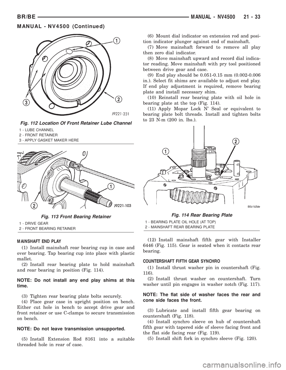
mallet.
(2) Install rear bearing plate to hold mainshaft
and rear bearing in position (Fig. 114).
NOTE: Do not install any end play shims at this
time.
(3) Tighten rear bearing plate bolts securely.
(4) Place gear case in upright position on bench.
Either cut hole in bench to accept drive gear and
front retainer or use C-clamps to secure transmission
on bench.
NOTE: Do not leave transmission unsupported.
(5) Install Extension Rod 8161 into a suitable
threaded hole in rear of case.(6) Mount dial indicator on extension rod and posi-
tion indicator plunger against end of mainshaft.
(7) Move mainshaft forward to remove all play
then zero dial indicator.
(8) Move mainshaft upward and record dial indica-
tor reading. Move mainshaft with pry tool positioned
between drive gear and case.
(9) End play should be 0.051-0.15 mm (0.002-0.006
in.). Select fit shims are available to adjust end play.
If end play adjustment is required, remove bearing
plate and install necessary shim.
(10) Reinstall rear bearing plate with oil hole in
bearing plate at the top (Fig. 114).
(11) Apply Mopar Lock N' Seal or equivalent to
bearing plate bolt threads. Install and tighten bolts
to 23 N´m (200 in. lbs.).
(12) Install mainshaft fifth gear with Installer
6446 (Fig. 115). Gear is seated when it contacts rear
bearing.
COUNTERSHAFT FIFTH GEAR SYNCHRO
(1) Install thrust washer pin in countershaft (Fig.
116).
(2) Install thrust washer on countershaft. Turn
washer until pin engages in washer notch (Fig. 117).
NOTE: The flat side of washer faces the rear and
cone side faces the front.
(3) Lubricate and install fifth gear bearing on
countershaft (Fig. 118).
(4) Install synchro sleeve on hub of countershaft
fifth gear with tapered side of sleeve facing front and
the flat side facing rear (Fig. 119).
(5) Install shift fork in synchro sleeve (Fig. 120).
Fig. 112 Location Of Front Retainer Lube Channel
1 - LUBE CHANNEL
2 - FRONT RETAINER
3 - APPLY GASKET MAKER HERE
Fig. 113 Front Bearing Retainer
1 - DRIVE GEAR
2 - FRONT BEARING RETAINER
Fig. 114 Rear Bearing Plate
1 - BEARING PLATE OIL HOLE (AT TOP)
2 - MAINSHAFT REAR BEARING PLATE
BR/BEMANUAL - NV4500 21 - 33
MANUAL - NV4500 (Continued)
Page 1582 of 2255
INPUT SHAFT END PLAY CHECK
NOTE: Overdrive unit must be installed in order to
correctly measure the input shaft end-play.
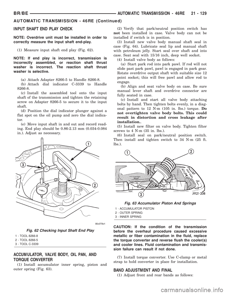
(1) Measure input shaft end play (Fig. 62).
NOTE: If end play is incorrect, transmission is
incorrectly assembled, or reaction shaft thrust
washer is incorrect. The reaction shaft thrust
washer is selective.
(a) Attach Adapter 8266-5 to Handle 8266-8.
(b) Attach dial indicator C-3339 to Handle
8266-8.
(c) Install the assembled tool onto the input
shaft of the transmission and tighten the retaining
screw on Adapter 8266-5 to secure it to the input
shaft.
(d) Position the dial indicator plunger against a
flat spot on the oil pump and zero the dial indica-
tor.
(e) Move input shaft in and out and record read-
ing. End play should be 0.86-2.13 mm (0.034-0.084
in.). Adjust as necessary.
ACCUMULATOR, VALVE BODY, OIL PAN, AND
TORQUE CONVERTER
(1) Install accumulator inner spring, piston and
outer spring (Fig. 63).(2) Verify that park/neutral position switch has
notbeen installed in case. Valve body can not be
installed if switch is in position.
(3) Install new valve body manual shaft seal in
case (Fig. 64). Lubricate seal lip and manual shaft
with petroleum jelly. Start seal over shaft and into
case. Seat seal with 15/16 inch, deep well socket.
(4) Install valve body as follows:
(a) Start park rod into park pawl. If rod will not
slide past park pawl, pawl is engaged in park gear.
Rotate overdrive output shaft with suitable size 12
point socket; this will free pawl and allow rod to
engage.
(b) Align and seat valve body on case. Be sure
manual lever shaft and overdrive connector are
fully seated in case.
(c) Install and start all valve body attaching
bolts by hand. Then tighten bolts evenly, in a diag-
onal pattern to 12 N´m (105 in. lbs.) torque.Do
not overtighten valve body bolts. This could
result in distortion and cross leakage after
installation..
(5) Install new filter on valve body. Tighten filter
screws to 4 N´m (35 in. lbs.).
(6) Install seal on park/neutral position switch.
Then install and tighten switch to 34 N´m (25 ft.
lbs.).
CAUTION: If the condition of the transmission
before the overhaul procedure caused excessive
metallic or fiber contamination in the fluid, replace
the torque converter and reverse flush the cooler(s)
and cooler lines. Fluid contamination and transmis-
sion failure can result if not done.
(7) Install torque converter. Use C-clamp or metal
strap to hold converter in place for installation.
BAND ADJUSTMENT AND FINAL
(1) Adjust front and rear bands as follows:
Fig. 62 Checking Input Shaft End Play
1 - TOOL 8266-8
2 - TOOL 8266-5
3 - TOOL C-3339
Fig. 63 Accumulator Piston And Springs
1 - ACCUMULATOR PISTON
2 - OUTER SPRING
3 - INNER SPRING
BR/BEAUTOMATIC TRANSMISSION - 46RE 21 - 129
AUTOMATIC TRANSMISSION - 46RE (Continued)