2002 DODGE RAM auxiliary battery location
[x] Cancel search: auxiliary battery locationPage 1233 of 2255

(11) Install the cylinder head cover and reusable
gasket (Fig. 85) (Refer to 9 - ENGINE/CYLINDER
HEAD/CYLINDER HEAD COVER(S) - INSTALLA-
TION).
(12) Install gear housing cover (Refer to 9 -
ENGINE/VALVE TIMING/GEAR HOUSING COVER
- INSTALLATION).
(13) Install the crankshaft damper (Fig. 83) (Refer
to 9 - ENGINE/ENGINE BLOCK/VIBRATION
DAMPER - INSTALLATION).
(14) Install the fan support/hub assembly (Fig. 82)
and tighten bolts to 24 N´m (18 ft. lbs.) torque.
(15) Install the crankcase breather housing (Refer
to 9 - ENGINE - INSTALLATION).
(16) Install the charge air cooler (with a/c con-
denser and auxiliary transmission oil cooler, if
equipped) and tighten the mounting bolts to 2 N´m
(17 in. lbs.) torque.
(17) Connect charge air cooler inlet and outlet
pipes. Tighten clamps to 10 N´m (100 in. lbs.) torque.
(18) Install the radiator upper support panel.
(19) Close radiator petcock and lower the radiator
into the engine compartment. Tighten the mounting
bolts to 11 N´m (95 in. lbs.) torque.
(20) Raise vehicle on hoist.
(21) Connect radiator lower hose and install
clamp.
(22) Connect transmission auxiliary oil cooler lines
(if equipped).
(23) Lower vehicle.
(24) Install the fan shroud and tighten the mount-
ing screws to 6 N´m (50 in. lbs.) torque.
(25) Install the viscous fan/drive assembly (Refer
to 7 - COOLING/ENGINE/RADIATOR FAN -
INSTALLATION).
(26) Install the coolant recovery and windshield
washer fluid reservoirs to the fan shroud.
(27) Connect the coolant recovery hose to the radi-
ator filler neck.
(28) Install the accessory drive belt (Refer to 7 -
COOLING/ACCESSORY DRIVE/DRIVE BELTS -
INSTALLATION).
(29) Install the front bumper assembly (Refer to 13
- FRAMES & BUMPERS/BUMPERS/FRONT
BUMPER - INSTALLATION).
(30) Add engine coolant (Refer to 7 - COOLING -
STANDARD PROCEDURE).
(31) Charge A/C system with refrigerant (if A/C
equipped) (Refer to 24 - HEATING & AIR CONDI-
TIONING/PLUMBING - STANDARD PROCEDURE).
(32) Connect the battery negative cables.
(33) Start engine and check for engine oil and cool-
ant leaks.CONNECTING ROD BEARINGS
STANDARD PROCEDUREÐCONNECTING ROD
BEARING AND CRANKSHAFT JOURNAL
CLEARANCE
Measure the connecting rod bore with the bearings
installed and the bolts tightened to 100 N´m (73 ft.
lbs.) torque.
Record the smaller diameter.
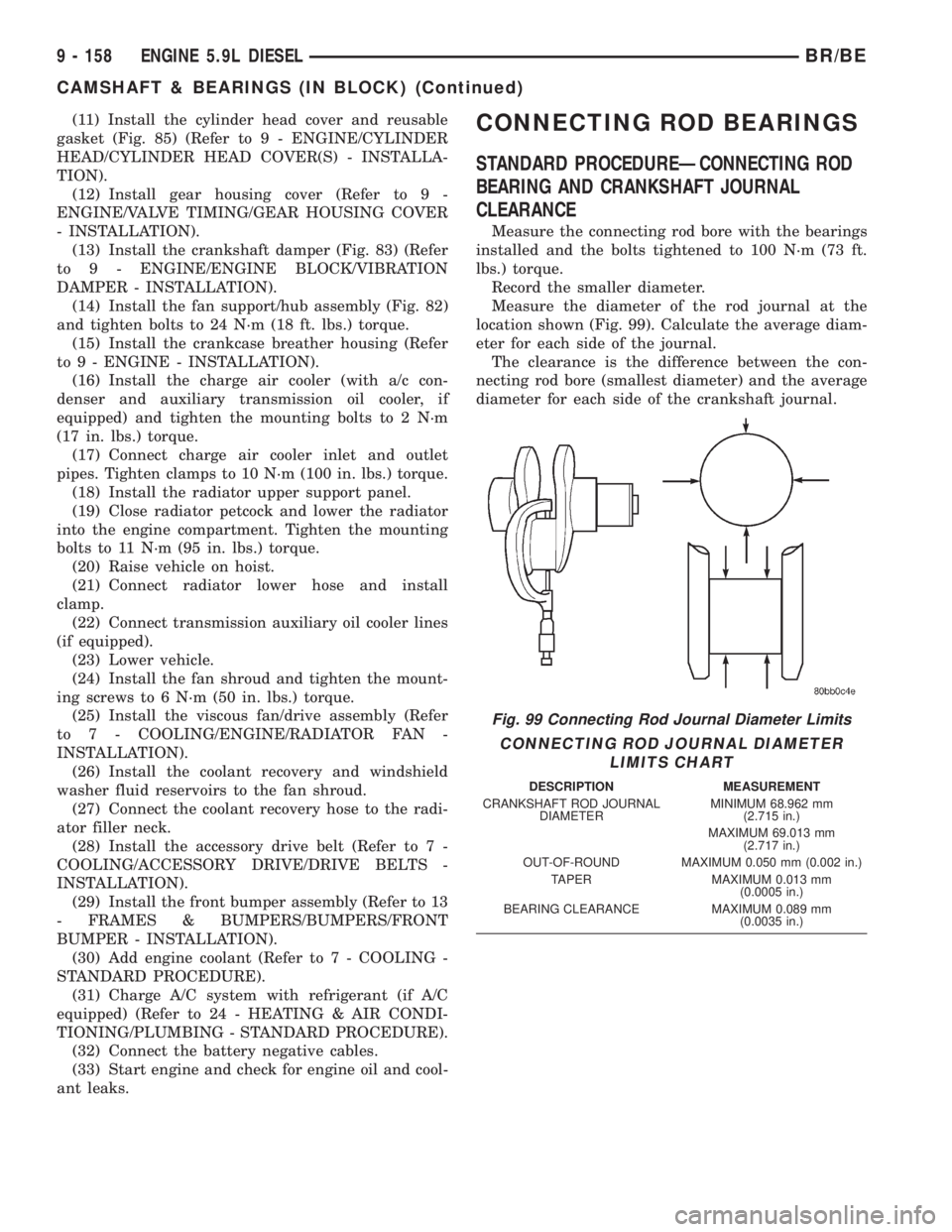
Measure the diameter of the rod journal at the
location shown (Fig. 99). Calculate the average diam-
eter for each side of the journal.
The clearance is the difference between the con-
necting rod bore (smallest diameter) and the average
diameter for each side of the crankshaft journal.
Fig. 99 Connecting Rod Journal Diameter Limits
CONNECTING ROD JOURNAL DIAMETER
LIMITS CHART
DESCRIPTION MEASUREMENT
CRANKSHAFT ROD JOURNAL
DIAMETERMINIMUM 68.962 mm
(2.715 in.)
MAXIMUM 69.013 mm
(2.717 in.)
OUT-OF-ROUND MAXIMUM 0.050 mm (0.002 in.)
TAPER MAXIMUM 0.013 mm
(0.0005 in.)
BEARING CLEARANCE MAXIMUM 0.089 mm
(0.0035 in.)
9 - 158 ENGINE 5.9L DIESELBR/BE
CAMSHAFT & BEARINGS (IN BLOCK) (Continued)
Page 1320 of 2255

ule is being installed, refer to Fuel Tank Module
Removal/Installation in this group.
(2) Place fuel tank on top of transmission jack.
(3) Install rubber fill and vent lines to tank.
Tighten hose clamps to 2.3 N´m (20 in. lbs.) torque.
(4) Raise tank into position while guiding fill and
vent hoses to body. Raise tank only enough to allow
access to top of tank.
(5)Gas Powered Engines:
(a) Connect electrical connector to fuel pump
module.
(b) Connect EVAP hoses at rollover valves.
(c) Connect fuel supply line at fuel filter/fuel
pressure regulator. Refer to Quick-Connect Fittings
for procedures.
(6)Diesel Powered Engines:
(a) Connect electrical connector to fuel tank
module.
(b) Connect fuel supply and fuel return lines to
fuel tank module fittings. Refer to Quick-Connect
Fittings in this group.
(7) Connect two mounting straps and mounting
strap nuts.
(8) Tighten strap nuts to 41 N´m (30 ft. lbs.)
torque. Do not over tighten retaining strap nuts.
(9) Remove transmission jack.
(10) Connect fuel filler tube assembly to body.
(11) If equipped, connect grounding wire (strap)
and screw.
(12) Refill fuel tank and inspect all hoses and lines
for leaks.
(13) Connect negative battery cable(s) to bat-
tery(s).
FUEL TANK CHECK VALVE
DESCRIPTION
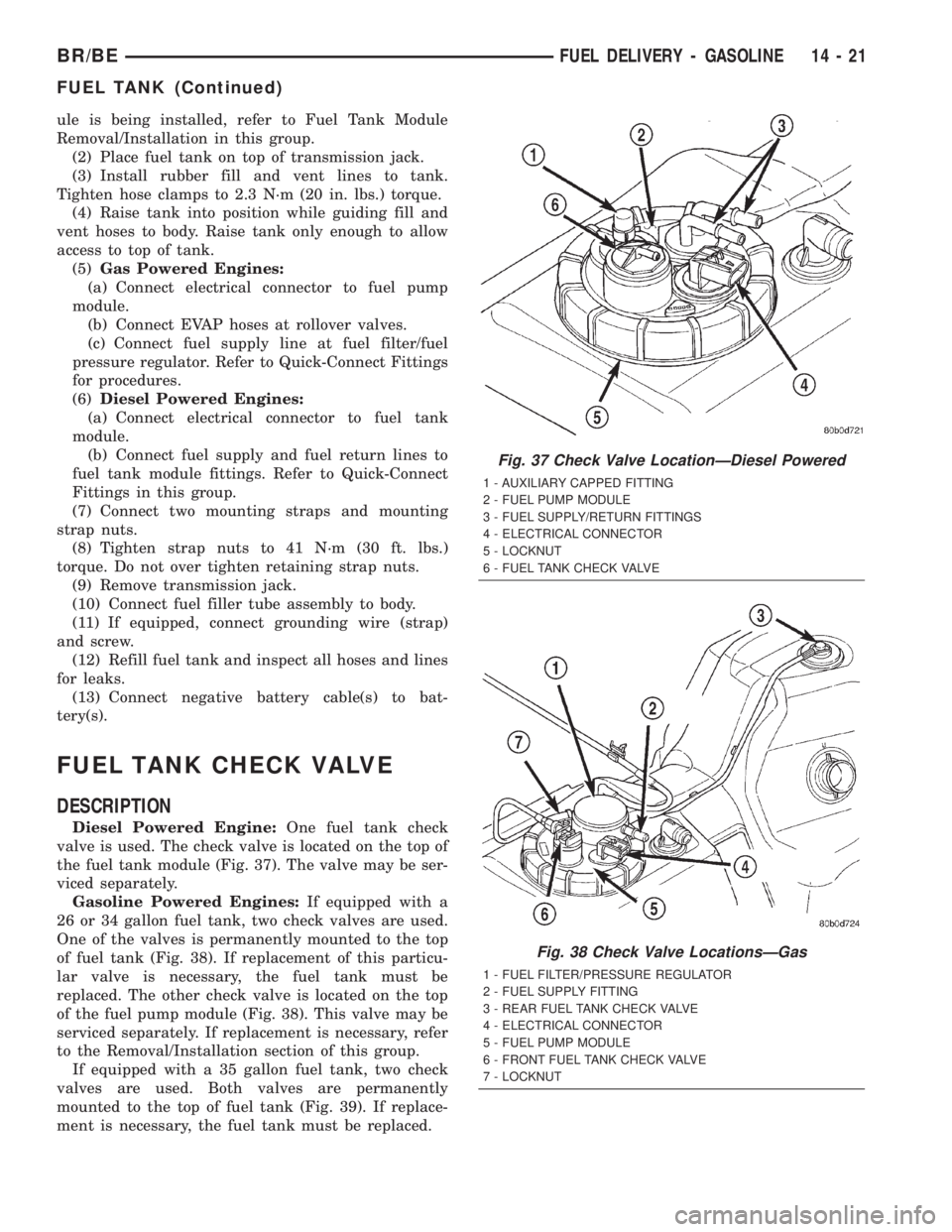
Diesel Powered Engine:One fuel tank check
valve is used. The check valve is located on the top of
the fuel tank module (Fig. 37). The valve may be ser-
viced separately.
Gasoline Powered Engines:If equipped with a
26 or 34 gallon fuel tank, two check valves are used.
One of the valves is permanently mounted to the top
of fuel tank (Fig. 38). If replacement of this particu-
lar valve is necessary, the fuel tank must be
replaced. The other check valve is located on the top
of the fuel pump module (Fig. 38). This valve may be
serviced separately. If replacement is necessary, refer
to the Removal/Installation section of this group.
If equipped with a 35 gallon fuel tank, two check
valves are used. Both valves are permanently
mounted to the top of fuel tank (Fig. 39). If replace-
ment is necessary, the fuel tank must be replaced.
Fig. 37 Check Valve LocationÐDiesel Powered
1 - AUXILIARY CAPPED FITTING
2 - FUEL PUMP MODULE
3 - FUEL SUPPLY/RETURN FITTINGS
4 - ELECTRICAL CONNECTOR
5 - LOCKNUT
6 - FUEL TANK CHECK VALVE
Fig. 38 Check Valve LocationsÐGas
1 - FUEL FILTER/PRESSURE REGULATOR
2 - FUEL SUPPLY FITTING
3 - REAR FUEL TANK CHECK VALVE
4 - ELECTRICAL CONNECTOR
5 - FUEL PUMP MODULE
6 - FRONT FUEL TANK CHECK VALVE
7 - LOCKNUT
BR/BEFUEL DELIVERY - GASOLINE 14 - 21
FUEL TANK (Continued)
Page 1321 of 2255

REMOVAL
WARNING: THE FUEL SYSTEM IS UNDER A CON-
STANT PRESSURE (EVEN WITH THE ENGINE OFF).
BEFORE SERVICING THE CHECK VALVE, FUEL
SYSTEM PRESSURE MUST BE RELEASED (GASO-
LINE POWERED ENGINES ONLY). REFER TO THE
FUEL PRESSURE RELEASE PROCEDURE IN
GROUP 14, FUEL SYSTEM.
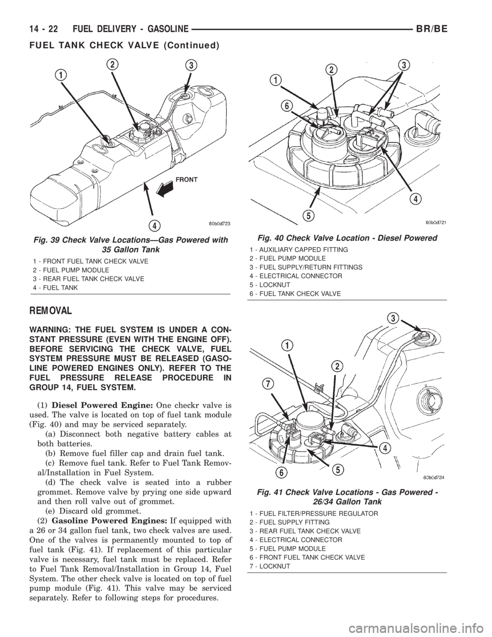
(1)Diesel Powered Engine:One checkr valve is
used. The valve is located on top of fuel tank module
(Fig. 40) and may be serviced separately.
(a) Disconnect both negative battery cables at
both batteries.
(b) Remove fuel filler cap and drain fuel tank.
(c) Remove fuel tank. Refer to Fuel Tank Remov-
al/Installation in Fuel System.
(d) The check valve is seated into a rubber
grommet. Remove valve by prying one side upward
and then roll valve out of grommet.
(e) Discard old grommet.
(2)Gasoline Powered Engines:
If equipped with
a 26 or 34 gallon fuel tank, two check valves are used.
One of the valves is permanently mounted to top of
fuel tank (Fig. 41). If replacement of this particular
valve is necessary, fuel tank must be replaced. Refer
to Fuel Tank Removal/Installation in Group 14, Fuel
System. The other check valve is located on top of fuel
pump module (Fig. 41). This valve may be serviced
separately. Refer to following steps for procedures.
Fig. 39 Check Valve LocationsÐGas Powered with
35 Gallon Tank
1 - FRONT FUEL TANK CHECK VALVE
2 - FUEL PUMP MODULE
3 - REAR FUEL TANK CHECK VALVE
4 - FUEL TANK
Fig. 40 Check Valve Location - Diesel Powered
1 - AUXILIARY CAPPED FITTING
2 - FUEL PUMP MODULE
3 - FUEL SUPPLY/RETURN FITTINGS
4 - ELECTRICAL CONNECTOR
5 - LOCKNUT
6 - FUEL TANK CHECK VALVE
Fig. 41 Check Valve Locations - Gas Powered -
26/34 Gallon Tank
1 - FUEL FILTER/PRESSURE REGULATOR
2 - FUEL SUPPLY FITTING
3 - REAR FUEL TANK CHECK VALVE
4 - ELECTRICAL CONNECTOR
5 - FUEL PUMP MODULE
6 - FRONT FUEL TANK CHECK VALVE
7 - LOCKNUT
14 - 22 FUEL DELIVERY - GASOLINEBR/BE
FUEL TANK CHECK VALVE (Continued)