2002 DODGE RAM seat adjustment
[x] Cancel search: seat adjustmentPage 219 of 2255

(3) Remove the front cable from the cable connec-
tor.
(4) Compress cable end fitting at underbody
bracket and remove the cable from the bracket.
(5) Lower vehicle.
(6) Push ball end of cable out of pedal clevis with
small screwdriver.
(7) Compress cable end fitting at the pedal bracket
and remove the cable (Fig. 55).
(8) Remove the left cowl trim and sill plate.
(9) Pull up the carpet and remove the cable from
the body clip.
(10) Pull up on the cable and remove the cable
with the body grommet.
INSTALLATION
INSTALLATION - REAR PARK BRAKE CABLE
(1) Push each cable end through the brake cable
support plate hole until the cable end fitting tabs
lock into place.
NOTE: Pull on the cable to ensure it is locked into
place.
(2) Push the cable through the frame bracket.
(3) Lock the left cable end fitting tabs into the
frame bracket hole.
(4) Install the rear cables into the tensioner rod
behind the rear of the brake assembly.(5) Install the cable to the intermediate cable con-
nector.
(6) Release and remove the lock out device.
(7) Perform the park brake adjustment procedure,
(Refer to 5 - BRAKES/PARKING BRAKE/CABLE
TENSIONER - ADJUSTMENTS).
(8) Remove the supports and lower the vehicle.
INSTALLATION - FRONT PARKING BRAKE
CABLE
(1) From inside the vehicle, insert the cable end
fitting into the hole in the pedal assembly.
(2) Seat the cable retainer in the pedal assembly.
(3) Engage the cable ball end in clevis on the pedal
assembly.
(4) Route the cable along the top of the wheel well
and clip in place.
(5) Route the cable through the floorpan and
install the body grommet.
(6) Place the carpet down and install the left cowl
trim and sill plate.
(7) Raise and support the vehicle.
(8) Route the cable through the underbody bracket
and seat the cable housing retainer in the bracket.
(9) Connect the cable to the cable connector.
(10) Perform the park brake adjustment proce-
dure, (Refer to 5 - BRAKES/PARKING BRAKE/CA-
BLE TENSIONER - ADJUSTMENTS).
(11) Lower the vehicle.
CABLE TENSIONER
ADJUSTMENTS
ADJUSTMENT
NOTE: Tensioner adjustment is only necessary
when the tensioner, or a cable has been replaced or
disconnected for service. When adjustment is nec-
essary, perform adjustment only as described in the
following procedure. This is necessary to avoid
faulty park brake operation.
(1) Raise the vehicle.
(2) Back off the cable tensioner adjusting nut to
create slack in the cables.
(3) Remove the rear wheel/tire assemblies. Then
remove the brake drum in hat assembly.
(4) Verify the brakes are in good condition and
operating properly.
(5) Verify the park brake cables operate freely and
are not binding, or seized.
(6) Check the rear brake shoe adjustment with
standard brake gauge.
Fig. 55 Parking Brake Pedal
1 - PARK BRAKE PEDAL
2 - FRONT CABLE
5 - 30 BRAKES - BASEBR/BE
CABLES (Continued)
Page 1100 of 2255
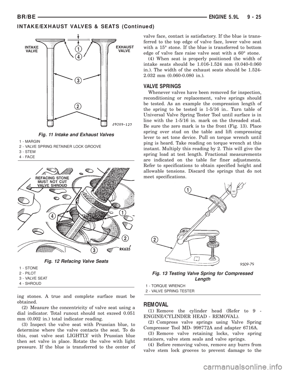
ing stones. A true and complete surface must be
obtained.
(2) Measure the concentricity of valve seat using a
dial indicator. Total runout should not exceed 0.051
mm (0.002 in.) total indicator reading.
(3) Inspect the valve seat with Prussian blue, to
determine where the valve contacts the seat. To do
this, coat valve seat LIGHTLY with Prussian blue
then set valve in place. Rotate the valve with light
pressure. If the blue is transferred to the center ofvalve face, contact is satisfactory. If the blue is trans-
ferred to the top edge of valve face, lower valve seat
with a 15É stone. If the blue is transferred to bottom
edge of valve face raise valve seat with a 60É stone.
(4) When seat is properly positioned the width of
intake seats should be 1.016-1.524 mm (0.040-0.060
in.). The width of the exhaust seats should be 1.524-
2.032 mm (0.060-0.080 in.).
VALVE SPRINGS
Whenever valves have been removed for inspection,
reconditioning or replacement, valve springs should
be tested. As an example the compression length of
the spring to be tested is 1-5/16 in.. Turn table of
Universal Valve Spring Tester Tool until surface is in
line with the 1-5/16 in. mark on the threaded stud.
Be sure the zero mark is to the front (Fig. 13). Place
spring over stud on the table and lift compressing
lever to set tone device. Pull on torque wrench until
ping is heard. Take reading on torque wrench at this
instant. Multiply this reading by 2. This will give the
spring load at test length. Fractional measurements
are indicated on the table for finer adjustments.
Refer to specifications to obtain specified height and
allowable tensions. Discard the springs that do not
meet specifications.
REMOVAL
(1) Remove the cylinder head (Refer to 9 -
ENGINE/CYLINDER HEAD - REMOVAL).
(2) Compress valve springs using Valve Spring
Compressor Tool MD- 998772A and adapter 6716A.
(3) Remove valve retaining locks, valve spring
retainers, valve stem seals and valve springs.
(4) Before removing valves, remove any burrs from
valve stem lock grooves to prevent damage to the
Fig. 11 Intake and Exhaust Valves
1 - MARGIN
2 - VALVE SPRING RETAINER LOCK GROOVE
3 - STEM
4-FACE
Fig. 12 Refacing Valve Seats
1-STONE
2 - PILOT
3 - VALVE SEAT
4 - SHROUD
Fig. 13 Testing Valve Spring for Compressed
Length
1 - TORQUE WRENCH
2 - VALVE SPRING TESTER
BR/BEENGINE 5.9L 9 - 25
INTAKE/EXHAUST VALVES & SEATS (Continued)
Page 1156 of 2255
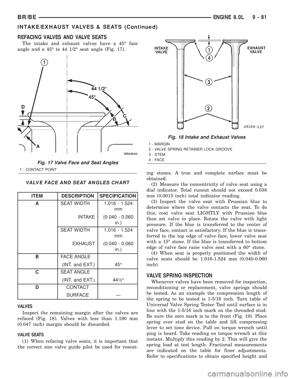
REFACING VALVES AND VALVE SEATS
The intake and exhaust valves have a 45É face
angle and a 45É to 44 1/2É seat angle (Fig. 17).
VALVE FACE AND SEAT ANGLES CHART
ITEM DESCRIPTION SPECIFICATION
ASEAT WIDTH 1.016 - 1.524
mm
INTAKE (0.040 - 0.060
in.)
SEAT WIDTH 1.016 - 1.524
mm
EXHAUST (0.040 - 0.060
in.)
BFACE ANGLE
(INT. and EXT.) 45É
CSEAT ANGLE
(INT. and EXT.) 44óÉ
DCONTACT
SURFACE Ð
VALVES
Inspect the remaining margin after the valves are
refaced (Fig. 18). Valves with less than 1.190 mm
(0.047 inch) margin should be discarded.
VALVE SEATS
(1) When refacing valve seats, it is important that
the correct size valve guide pilot be used for reseat-ing stones. A true and complete surface must be
obtained.
(2) Measure the concentricity of valve seat using a
dial indicator. Total runout should not exceed 0.038
mm (0.0015 inch) total indicator reading.
(3) Inspect the valve seat with Prussian blue to
determine where the valve contacts the seat. To do
this, coat valve seat LIGHTLY with Prussian blue
then set valve in place. Rotate the valve with light
pressure. If the blue is transferred to the center of
valve face, contact is satisfactory. If the blue is trans-
ferred to the top edge of valve face, lower valve seat
with a 15É stone. If the blue is transferred to bottom
edge of valve face raise valve seat with a 60É stone.
(4) When seat is properly positioned the width of
valve seats should be 1.016-1.524 mm (0.040-0.060
inch).
VALVE SPRING INSPECTION
Whenever valves have been removed for inspection,
reconditioning or replacement, valve springs should
be tested. As an example the compression length of
the spring to be tested is 1-5/16 inch. Turn table of
Universal Valve Spring Tester Tool until surface is in
line with the 1-5/16 inch mark on the threaded stud.
Be sure the zero mark is to the front (Fig. 19). Place
spring over stud on the table and lift compressing
lever to set tone device. Pull on torque wrench until
ping is heard. Take reading on torque wrench at this
instant. Multiply this reading by 2. This will give the
spring load at test length. Fractional measurements
are indicated on the table for finer adjustments.
Refer to specifications to obtain specified height and
Fig. 17 Valve Face and Seat Angles
1 - CONTACT POINT
Fig. 18 Intake and Exhaust Valves
1 - MARGIN
2 - VALVE SPRING RETAINER LOCK GROOVE
3 - STEM
4-FACE
BR/BEENGINE 8.0L 9 - 81
INTAKE/EXHAUST VALVES & SEATS (Continued)
Page 1188 of 2255
ENGINE 5.9L DIESEL
TABLE OF CONTENTS
page page
ENGINE 5.9L DIESEL
DESCRIPTION........................115
DIAGNOSIS AND TESTING
DIAGNOSIS AND TESTINGÐENGINE
DIAGNOSIS - MECHANICAL............116
DIAGNOSIS AND TESTINGÐSMOKE
DIAGNOSIS CHARTS..................118
STANDARD PROCEDURE
STANDARD PROCEDURE - FORM-IN-
PLACE GASKETS AND SEALERS........122
STANDARD PROCEDURE - REPAIR
DAMAGED OR WORN THREADS........122
STANDARD PROCEDUREÐHYDROSTATIC
LOCK..............................122
REMOVAL
REMOVALÐENGINE..................123
REMOVALÐCRANKCASE BREATHER
VAPOR CANISTER...................125
INSTALLATION
INSTALLATIONÐENGINE..............125
INSTALLATIONÐCRANKCASE BREATHER
VAPOR CANISTER...................126
SPECIFICATIONS
5.9L DIESEL........................127
TORQUE...........................127
SPECIAL TOOLS
5.9L DIESEL ENGINE.................128
ENGINE DATA PLATE
DESCRIPTION........................129
AIR CLEANER ELEMENT
REMOVAL............................129
INSTALLATION........................130
CYLINDER HEAD
DESCRIPTION........................130
REMOVAL............................130
CLEANING
CLEANINGÐCYLINDER HEAD..........134
CLEANINGÐCROSSHEADS............134
CLEANINGÐPUSHRODS..............134
INSPECTION
INSPECTIONÐCYLINDER HEAD.........134
INSPECTIONÐCROSSHEADS..........135
INSPECTIONÐPUSHRODS.............135
INSTALLATION........................136
CYLINDER HEAD COVER(S)
REMOVAL............................137
CLEANING...........................137
INSPECTION.........................138
INSTALLATION........................138INTAKE/EXHAUST VALVES & SEATS
DESCRIPTION........................138
STANDARD PROCEDURE
STANDARD PROCEDURE -
VALVES,GUIDES AND SPRINGS.........138
STANDARD PROCEDUREÐVALVE LASH
ADJUSTMENT AND VERIFICATION.......141
REMOVAL............................143
INSTALLATION........................143
ROCKER ARM / ADJUSTER ASSY
DESCRIPTION........................145
REMOVAL............................145
CLEANING...........................146
INSPECTION.........................146
INSTALLATION........................148
ENGINE BLOCK
STANDARD PROCEDURE
STANDARD PROCEDURE - CYLINDER
BLOCK REFACING...................148
STANDARD PROCEDURE - CYLINDER
BORE - DE-GLAZE...................148
STANDARD PROCEDUREÐCYLINDER
BORE REPAIR.......................149
STANDARD PROCEDUREÐCAM BORE
REPAIR ............................151
INSPECTION.........................151
CAMSHAFT & BEARINGS (IN BLOCK)
REMOVAL
REMOVALÐCAMSHAFT BEARINGS......152
REMOVALÐCAMSHAFT...............152
INSPECTION.........................155
INSTALLATION
INSTALLATIONÐCAMSHAFT BEARINGS . . 157
INSTALLATIONÐCAMSHAFT............157
CONNECTING ROD BEARINGS
STANDARD PROCEDUREÐCONNECTING
ROD BEARING AND CRANKSHAFT
JOURNAL CLEARANCE................158
CRANKSHAFT
DESCRIPTION........................159
CRANKSHAFT MAIN BEARINGS
STANDARD PROCEDUREÐMAIN BEARING
CLEARANCE........................159
CRANKSHAFT OIL SEAL - FRONT
REMOVAL............................160
INSTALLATION........................160
CRANKSHAFT OIL SEAL - REAR
REMOVAL............................161
INSTALLATION........................162
BR/BEENGINE 5.9L DIESEL 9 - 113
Page 1195 of 2255
EXCESSIVE WHITE SMOKE
POSSIBLE CAUSE CORRECTION
Engine coolant temperature sensor malfunctioning. A DTC should have been set. Refer to Powertrain
Diagnostic Procedures Information. Also check
thermostat operation (Refer to 7 - COOLING/ENGINE/
ENGINE COOLANT THERMOSTAT - DIAGNOSIS AND
TESTING).
Engine Control Module (ECM) not calibrated or has
incorrect calibration.A DTC should have been set. Refer to Powertrain
Diagnostic Procedures Information.
Fuel filter plugged. Perform Fuel Pressure Drop Test (Refer to 14 - FUEL
SYSTEM/FUEL DELIVERY/FUEL TRANSFER PUMP -
DIAGNOSIS AND TESTING).
Fuel grade not correct or fuel quality is poor. Temporarily change fuel brands and note condition.
Change brand if necessary.
Fuel heater element or fuel heater temperature sensor
malfunctioning. This will cause wax type build-up in fuel
filter.Refer to Fuel Heater Testing (Refer to 14 - FUEL
SYSTEM/FUEL DELIVERY/FUEL HEATER -
DIAGNOSIS AND TESTING).
Fuel injector malfunctioning. A DTC should have been set. Perform9Cylinder
Balance Test9using DRB scan tool to isolate individual
cylinders. Also refer to Powertrain Diagnostic
Procedures Information and, (Refer to 14 - FUEL
SYSTEM/FUEL INJECTION/FUEL INJECTOR -
DIAGNOSIS AND TESTING).
Fuel injector hold-downs loose. Torque to specifications.
Fuel injector protrusion not correct. Check washer (shim) at bottom of fuel injector for
correct thickness. (Refer to 14 - FUEL SYSTEM/FUEL
INJECTION/FUEL INJECTOR - INSTALLATION)
Fuel injection pump malfunctioning. A DTC should have been set. Refer to Powertrain
Diagnostic Procedures Information.
Fuel supply side restriction to transfer pump. Refer to Fuel Transfer Pump Pressure (Refer to 14 -
FUEL SYSTEM/FUEL DELIVERY/FUEL TRANSFER
PUMP - DIAGNOSIS AND TESTING)
Fuel transfer (lift) pump malfunctioning. A DTC should have been set. Refer to Powertrain
Diagnostic Procedures Information. Also refer to Fuel
Transfer Pump Pressure Testing (Refer to 14 - FUEL
SYSTEM/FUEL DELIVERY/FUEL TRANSFER PUMP -
DIAGNOSIS AND TESTING).
Intake/Exhaust valve adjustments not correct (too tight). (Refer to 9 - ENGINE/CYLINDER HEAD/INTAKE/
EXHAUST VALVES & SEATS - STANDARD
PROCEDURE).
Intake manifold air temperature sensor malfunctioning. A DTC should have been set. Refer to Powertrain
Diagnostic Procedures Information.
Intake manifold heater circuit not functioning correctly in
cold weather.A DTC should have been set. Refer to Powertrain
Diagnostic Procedures Information. Also check heater
elements for correct operation.
Intake manifold heater elements not functioning
correctly in cold weather.A diagnostic trouble code WILL NOT BE SET if heater
elements are malfunctioning. Refer to NTC tests in
Powertrain Diagnostic Procedures Information.
Internal engine damage (scuffed cylinder). Analyze engine oil and inspect oil filter to locate area of
probable damage.
9 - 120 ENGINE 5.9L DIESELBR/BE
ENGINE 5.9L DIESEL (Continued)
Page 1216 of 2255
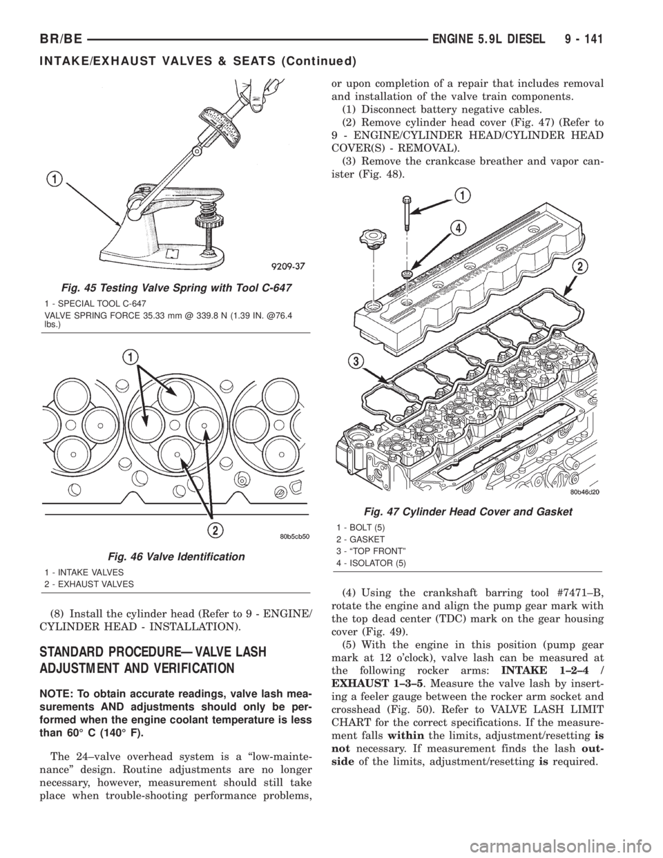
(8) Install the cylinder head (Refer to 9 - ENGINE/
CYLINDER HEAD - INSTALLATION).
STANDARD PROCEDUREÐVALVE LASH
ADJUSTMENT AND VERIFICATION
NOTE: To obtain accurate readings, valve lash mea-
surements AND adjustments should only be per-
formed when the engine coolant temperature is less
than 60É C (140É F).
The 24±valve overhead system is a ªlow-mainte-
nanceº design. Routine adjustments are no longer
necessary, however, measurement should still take
place when trouble-shooting performance problems,or upon completion of a repair that includes removal
and installation of the valve train components.
(1) Disconnect battery negative cables.
(2) Remove cylinder head cover (Fig. 47) (Refer to
9 - ENGINE/CYLINDER HEAD/CYLINDER HEAD
COVER(S) - REMOVAL).
(3) Remove the crankcase breather and vapor can-
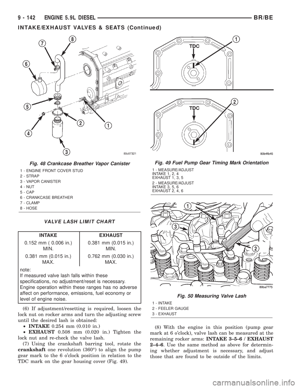
ister (Fig. 48).
(4) Using the crankshaft barring tool #7471±B,
rotate the engine and align the pump gear mark with
the top dead center (TDC) mark on the gear housing
cover (Fig. 49).
(5) With the engine in this position (pump gear
mark at 12 o'clock), valve lash can be measured at
the following rocker arms:INTAKE 1±2±4 /
EXHAUST 1±3±5. Measure the valve lash by insert-
ing a feeler gauge between the rocker arm socket and
crosshead (Fig. 50). Refer to VALVE LASH LIMIT
CHART for the correct specifications. If the measure-
ment fallswithinthe limits, adjustment/resettingis
notnecessary. If measurement finds the lashout-
sideof the limits, adjustment/resettingisrequired.
Fig. 45 Testing Valve Spring with Tool C-647
1 - SPECIAL TOOL C-647
VALVE SPRING FORCE 35.33 mm @ 339.8 N (1.39 IN. @76.4
lbs.)
Fig. 46 Valve Identification
1 - INTAKE VALVES
2 - EXHAUST VALVES
Fig. 47 Cylinder Head Cover and Gasket
1 - BOLT (5)
2 - GASKET
3 - ªTOP FRONTº
4 - ISOLATOR (5)
BR/BEENGINE 5.9L DIESEL 9 - 141
INTAKE/EXHAUST VALVES & SEATS (Continued)
Page 1217 of 2255
VALVE LASH LIMIT CHART
INTAKE EXHAUST
0.152 mm ( 0.006 in.)
MIN.0.381 mm (0.015 in.)
MIN.
0.381 mm (0.015 in.)
MAX.0.762 mm (0.030 in.)
MAX.
note:
If measured valve lash falls within these
specifications, no adjustment/reset is necessary.
Engine operation within these ranges has no adverse
affect on performance, emissions, fuel economy or
level of engine noise.
(6) If adjustment/resetting is required, loosen the
lock nut on rocker arms and turn the adjusting screw
until the desired lash is obtained:
²INTAKE0.254 mm (0.010 in.)
²EXHAUST0.508 mm (0.020 in.) Tighten the
lock nut and re-check the valve lash.
(7) Using the crankshaft barring tool, rotate the
crankshaftone revolution (360É) to align the pump
gear mark to the 6 o'clock position in relation to the
TDC mark on the gear housing cover (Fig. 49).(8) With the engine in this position (pump gear
mark at 6 o'clock), valve lash can be measured at the
remaining rocker arms:INTAKE 3±5±6 / EXHAUST
2±4±6. Use the same method as above for determin-
ing whether adjustment is necessary, and adjust
those that are found to be outside of the limits.
Fig. 48 Crankcase Breather Vapor Canister
1 - ENGINE FRONT COVER STUD
2 - STRAP
3 - VAPOR CANISTER
4 - NUT
5 - CAP
6 - CRANKCASE BREATHER
7 - CLAMP
8 - HOSE
Fig. 49 Fuel Pump Gear Timing Mark Orientation
1 - MEASURE/ADJUST
INTAKE 1, 2, 4
EXHAUST 1, 3, 5
2 - MEASURE/ADJUST
INTAKE 3, 5, 6
EXHAUST 2, 4, 6
Fig. 50 Measuring Valve Lash
1 - INTAKE
2 - FEELER GAUGE
3 - EXHAUST
9 - 142 ENGINE 5.9L DIESELBR/BE
INTAKE/EXHAUST VALVES & SEATS (Continued)
Page 1220 of 2255
original locations (Fig. 53). Tighten bolts to 36 N´m
(27 ft. lbs.) torque.
(4)Verify valve lash adjustment (Refer to 9 -
ENGINE/CYLINDER HEAD/INTAKE/EXHAUST
VALVES & SEATS - STANDARD PROCEDURE).
(5) Install cylinder head cover and reusable gasket
(Fig. 52) (Refer to 9 - ENGINE/CYLINDER HEAD/
CYLINDER HEAD COVER(S) - INSTALLATION).
(6) Install the accessory drive belt (Refer to 7 -
COOLING/ACCESSORY DRIVE/DRIVE BELTS -
INSTALLATION).
(7) Connect battery negative cables.
ROCKER ARM / ADJUSTER
ASSY
DESCRIPTION
The 24±valve overhead system incorporates rocker
arms that are designed to allow fuel injector service
without removing the rocker arms and pedestals. The
unique intake and exhaust rocker arms have their
own rocker shafts and are lubricated by passages
intersecting the cylinder block main oil rifle. Cross-
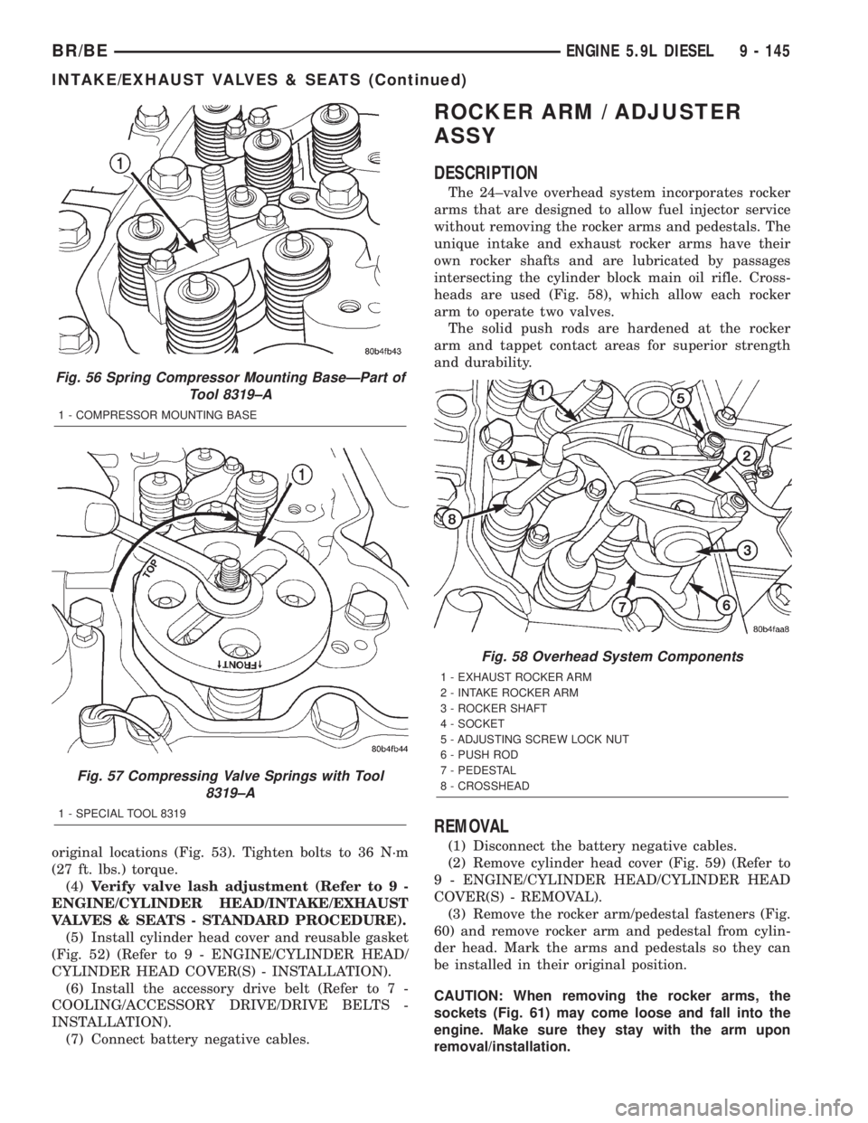
heads are used (Fig. 58), which allow each rocker
arm to operate two valves.
The solid push rods are hardened at the rocker
arm and tappet contact areas for superior strength
and durability.
REMOVAL
(1) Disconnect the battery negative cables.
(2) Remove cylinder head cover (Fig. 59) (Refer to
9 - ENGINE/CYLINDER HEAD/CYLINDER HEAD
COVER(S) - REMOVAL).
(3) Remove the rocker arm/pedestal fasteners (Fig.
60) and remove rocker arm and pedestal from cylin-
der head. Mark the arms and pedestals so they can
be installed in their original position.
CAUTION: When removing the rocker arms, the
sockets (Fig. 61) may come loose and fall into the
engine. Make sure they stay with the arm upon
removal/installation.
Fig. 56 Spring Compressor Mounting BaseÐPart of
Tool 8319±A
1 - COMPRESSOR MOUNTING BASE
Fig. 57 Compressing Valve Springs with Tool
8319±A
1 - SPECIAL TOOL 8319
Fig. 58 Overhead System Components
1 - EXHAUST ROCKER ARM
2 - INTAKE ROCKER ARM
3 - ROCKER SHAFT
4 - SOCKET
5 - ADJUSTING SCREW LOCK NUT
6 - PUSH ROD
7 - PEDESTAL
8 - CROSSHEAD
BR/BEENGINE 5.9L DIESEL 9 - 145
INTAKE/EXHAUST VALVES & SEATS (Continued)