2002 DODGE RAM relay
[x] Cancel search: relayPage 208 of 2255
HYDRAULIC BOOSTER DIAGNOSIS CHART
CONDITION POSSIBLE CAUSES CORRECTION
Slow Brake Pedal Return 1. Excessive seal friction in booster. 1. Replace booster.
2. Faulty spool valve action. 2. Replace booster.
3. Restriction in booster return hose. 3. Replace hose.
4. Damaged input rod. 4. Replace booster.
Excessive Brake Pedal
Effort.1. Internal or external seal leakage. 1. Replace booster.
2. Faulty steering pump. 2. Replace pump.
Brakes Self Apply 1. Dump valve faulty. 1. Replace booster.
2. Contamination in hydraulic
system.2. Flush hydraulic system and replace
booster.
3. Restriction in booster return hose. 3. Replace hose.
Booster Chatter, Pedal
Vibration1. Slipping pump belt. 1. Replace power steering belt.
2. Low pump fluid level. 2. Fill pump and check for leaks.
Grabbing Brakes 1. Low pump flow. 1. Test and repair/replace pump.
2. Faulty spool valve action. 2. Replace booster.
STANDARD PROCEDURE - BLEEDING
The hydraulic booster is generally self-bleeding,
this procedure will normally bleed the air from the
booster. Normal driving and operation of the unit will
remove any remaining trapped air.
(1) Fill power steering pump reservoir.
(2) Disconnect fuel shutdown relay and crank the
engine for several seconds, Refer to Fuel System for
relay location and WARNING.
(3) Check fluid level and add if necessary.
(4) Connect fuel shutdown relay and start the
engine.
(5) Turn the steering wheel slowly from lock to
lock twice.
(6) Stop the engine and discharge the accumulator
by depressing the brake pedal 5 times.
(7) Start the engine and turn the steering wheel
slowly from lock to lock twice.
(8) Turn off the engine and check fluid level and
add if necessary.
NOTE: If fluid foaming occurs, wait for foam to dis-
sipate and repeat steps 7 and 8.
REMOVAL
NOTE: If the booster is being replaced because the
power steering fluid is contaminated, flush the
power steering system before replacing the booster.(1) With engine off depress the brake pedal 5
times to discharge the accumulator.
(2) Remove brake lines from master cylinder.
(3) Remove mounting nuts from the master cylin-
der.
(4) Remove the bracket from the hydraulic booster
lines and master cylinder mounting studs.
(5) Remove the master cylinder.
(6) Remove the return hose and the two pressure
lines from the hydraulic booster (Fig. 28).
(7) Remove the booster push rod clip, washer and
rod remove from the brake pedal. (Fig. 29).
(8) Remove the mounting nuts from the hydraulic
booster and remove the booster (Fig. 30).
INSTALLATION
(1) Install the hydraulic booster and tighten the
mounting nuts to 28 N´m (21 ft. lbs.).
(2) Install the booster push rod, washer and clip
onto the brake pedal.
(3) Install the master cylinder on the mounting
studs. and tighten the mounting nuts to 23 N´m (17
ft. lbs.).
(4) Install the brake lines to the master cylinder
and tighten to 19-200 N´m (170-200 in. lbs.).
(5) Install the hydraulic booster line bracket onto
the master cylinder mounting studs.
(6) Install the master cylinder mounting nuts and
tighten to 23 N´m (17 ft. lbs.).
BR/BEBRAKES - BASE 5 - 19
POWER BRAKE BOOSTER (Continued)
Page 248 of 2255
(7) Position clutch fluid reservoir on dash panel
and install reservoir screws. Tighten screws to 5 N´m
(40 in. lbs.).
(8) Install the plastic clip securing the hydraulic
line to the dash panel into the lower dash panel
flange.
(9) Install the plastic clip securing the hydraulic
line to the dash panel onto the upper dash panel
stud.
(10) Raise vehicle.
(11) Install slave cylinder. Be sure cap at end of
cylinder rod is seated in release lever. Check this
before installing cylinder attaching nuts.
NOTE: If new linkage is being installed, do not
remove the plastic shipping strap from slave cylin-
der push rod. The shipping strap will break on its
own upon the first clutch application.
(12) Install and tighten slave cylinder attaching
nuts to 23 N´m (200 in. lbs.).
(13) If a new clutch linkage is being installed, con-
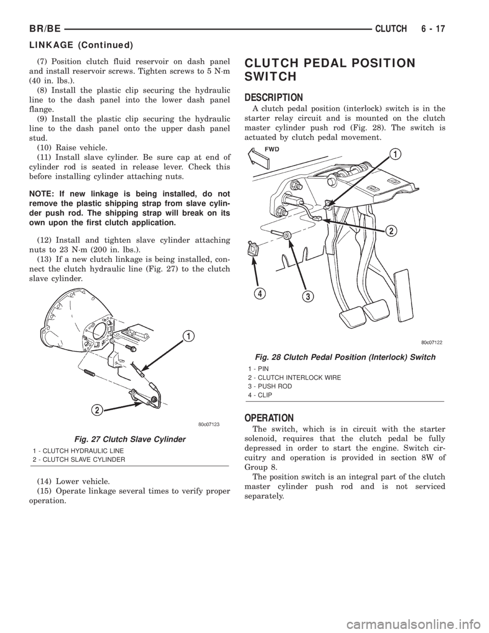
nect the clutch hydraulic line (Fig. 27) to the clutch
slave cylinder.
(14) Lower vehicle.
(15) Operate linkage several times to verify proper
operation.CLUTCH PEDAL POSITION
SWITCH
DESCRIPTION
A clutch pedal position (interlock) switch is in the
starter relay circuit and is mounted on the clutch
master cylinder push rod (Fig. 28). The switch is
actuated by clutch pedal movement.
OPERATION
The switch, which is in circuit with the starter
solenoid, requires that the clutch pedal be fully
depressed in order to start the engine. Switch cir-
cuitry and operation is provided in section 8W of
Group 8.
The position switch is an integral part of the clutch
master cylinder push rod and is not serviced
separately.
Fig. 27 Clutch Slave Cylinder
1 - CLUTCH HYDRAULIC LINE
2 - CLUTCH SLAVE CYLINDER
Fig. 28 Clutch Pedal Position (Interlock) Switch
1 - PIN
2 - CLUTCH INTERLOCK WIRE
3 - PUSH ROD
4 - CLIP
BR/BECLUTCH 6 - 17
LINKAGE (Continued)
Page 254 of 2255
DIAGNOSIS AND TESTINGÐON-BOARD
DIAGNOSTICS (OBD)
COOLING SYSTEM RELATED DIAGNOSTICS
The powertrain control module (PCM) has been
programmed to monitor certain cooling system com-
ponents:
²If the engine has remained cool for too long a
period, such as with a stuck open thermostat, a Diag-
nostic Trouble Code (DTC) can be set.
²If an open or shorted condition has developed in
the relay circuit controlling the electric radiator fan,
a Diagnostic Trouble Code (DTC) can be set.
If the problem is sensed in a monitored circuit
often enough to indicated an actual problem, a DTC
is stored. The DTC will be stored in the PCM mem-
ory for eventual display to the service technician.
(Refer to 25 - EMISSIONS CONTROL - DESCRIP-
TION).
ACCESSING DIAGNOSTIC TROUBLE CODES
To read DTC's and to obtain cooling system data,
(Refer to 25 - EMISSIONS CONTROL - DESCRIP-
TION).
ERASING TROUBLE CODES
After the problem has been repaired, use the DRB
scan tool to erase a DTC. Refer to the appropriate
Powertrain Diagnostic Procedures service informa-
tion for operation of the DRB scan tool.
DIAGNOSIS AND TESTING - COOLING SYSTEM
LEAKS
ULTRAVIOLET LIGHT METHOD
A leak detection additive is available through the
parts department that can be added to cooling sys-
tem. The additive is highly visible under ultraviolet
light (black light). Pour one ounce of additive into
cooling system. Place heater control unit in HEAT
position. Start and operate engine until radiator
upper hose is warm to touch. Aim the commercially
available black light tool at components to be
checked. If leaks are present, black light will cause
additive to glow a bright green color.
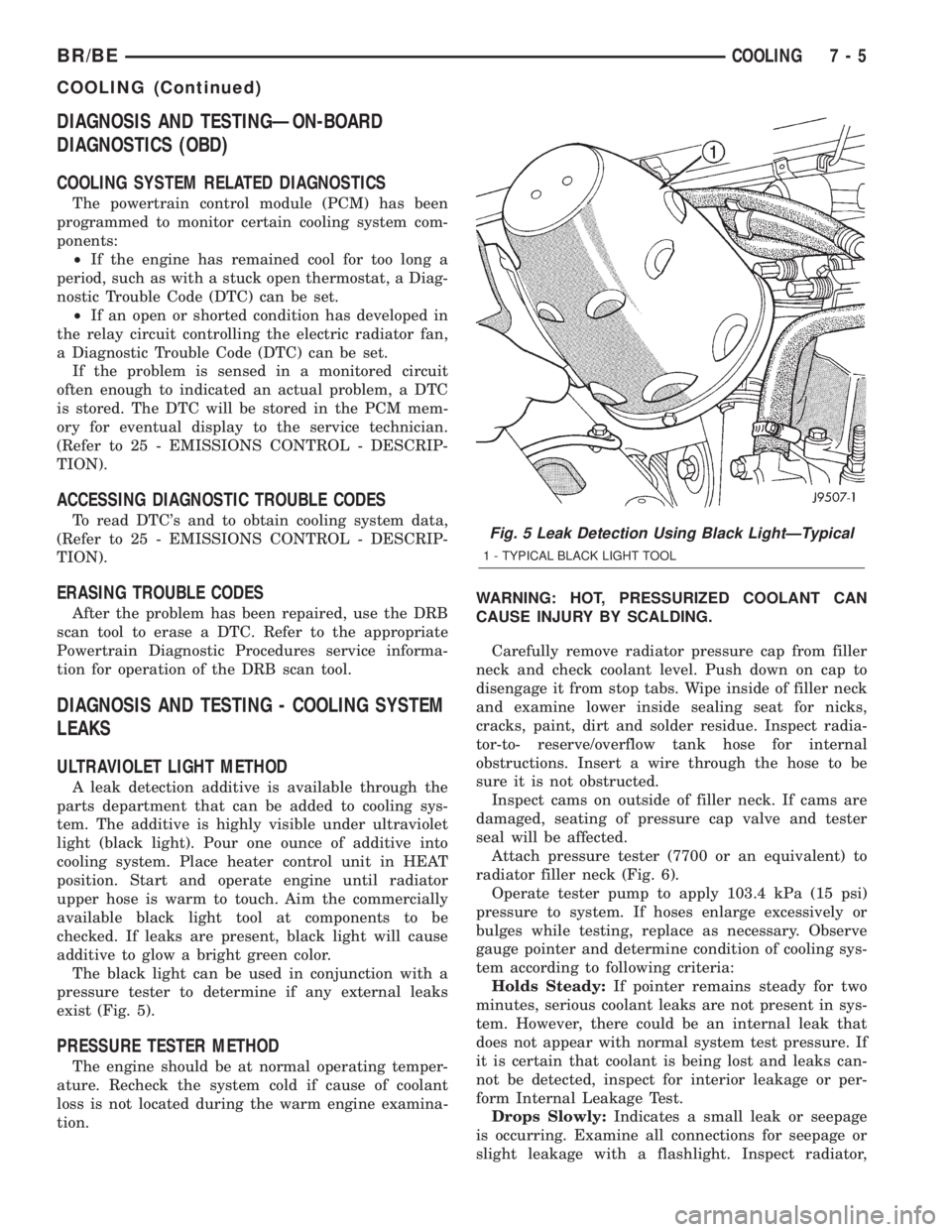
The black light can be used in conjunction with a
pressure tester to determine if any external leaks
exist (Fig. 5).
PRESSURE TESTER METHOD
The engine should be at normal operating temper-
ature. Recheck the system cold if cause of coolant
loss is not located during the warm engine examina-
tion.WARNING: HOT, PRESSURIZED COOLANT CAN
CAUSE INJURY BY SCALDING.
Carefully remove radiator pressure cap from filler
neck and check coolant level. Push down on cap to
disengage it from stop tabs. Wipe inside of filler neck
and examine lower inside sealing seat for nicks,
cracks, paint, dirt and solder residue. Inspect radia-
tor-to- reserve/overflow tank hose for internal
obstructions. Insert a wire through the hose to be
sure it is not obstructed.
Inspect cams on outside of filler neck. If cams are
damaged, seating of pressure cap valve and tester
seal will be affected.
Attach pressure tester (7700 or an equivalent) to
radiator filler neck (Fig. 6).
Operate tester pump to apply 103.4 kPa (15 psi)
pressure to system. If hoses enlarge excessively or
bulges while testing, replace as necessary. Observe
gauge pointer and determine condition of cooling sys-
tem according to following criteria:
Holds Steady:If pointer remains steady for two
minutes, serious coolant leaks are not present in sys-
tem. However, there could be an internal leak that
does not appear with normal system test pressure. If
it is certain that coolant is being lost and leaks can-
not be detected, inspect for interior leakage or per-
form Internal Leakage Test.
Drops Slowly:Indicates a small leak or seepage
is occurring. Examine all connections for seepage or
slight leakage with a flashlight. Inspect radiator,
Fig. 5 Leak Detection Using Black LightÐTypical
1 - TYPICAL BLACK LIGHT TOOL
BR/BECOOLING 7 - 5
COOLING (Continued)
Page 296 of 2255

ENGINE COOLANT TEMP
SENSOR - 5.9L
DESCRIPTION
The Engine Coolant Temperature (ECT) sensor is
used to sense engine coolant temperature. The sensor
protrudes into an engine water jacket.
The ECT sensor is a two-wire Negative Thermal
Coefficient (NTC) sensor. Meaning, as engine coolant
temperature increases, resistance (voltage) in the
sensor decreases. As temperature decreases, resis-
tance (voltage) in the sensor increases.
OPERATION
At key-on, the Powertrain Control Module (PCM)
sends out a regulated 5 volt signal to the ECT sensor.
The PCM then monitors the signal as it passes
through the ECT sensor to the sensor ground (sensor
return).
When the engine is cold, the PCM will operate in
Open Loop cycle. It will demand slightly richer air-
fuel mixtures and higher idle speeds. This is done
until normal operating temperatures are reached.
The PCM uses inputs from the ECT sensor for the
following calculations:
²for engine coolant temperature gauge operation
through CCD or PCI (J1850) communications
²Injector pulse-width
²Spark-advance curves
²ASD relay shut-down times
²Idle Air Control (IAC) motor key-on steps
²Pulse-width prime-shot during cranking
²O2 sensor closed loop times
²Purge solenoid on/off times
²EGR solenoid on/off times (if equipped)
²Leak Detection Pump operation (if equipped)
²Radiator fan relay on/off times (if equipped)²Target idle speed
REMOVAL
WARNING: HOT, PRESSURIZED COOLANT CAN
CAUSE INJURY BY SCALDING. COOLING SYSTEM
MUST BE PARTIALLY DRAINED BEFORE REMOV-
ING THE COOLANT TEMPERATURE SENSOR.
REFER TO GROUP 7, COOLING.
(1) Partially drain cooling system (Refer to 7 -
COOLING - STANDARD PROCEDURE).
(2) Remove air cleaner assembly.
(3) Disconnect electrical connector from sensor
(Fig. 14).
(4)Engines with air conditioning:When
removing the connector from sensor, do not pull
directly on wiring harness. Fabricate an L-shaped
hook tool from a coat hanger (approximately eight
inches long). Place the hook part of tool under the
connector for removal. The connector is snapped onto
the sensor. It is not equipped with a lock type tab.
(5) Remove sensor from intake manifold.
INSTALLATION
(1) Install sensor.
(2) Tighten to 6±8 N´m (55±75 in. lbs.) torque.
(3) Connect electrical connector to sensor. The sen-
sor connector is symmetrical (not indexed). It can be
installed to the sensor in either direction.
(4) Install air cleaner assembly.
(5) Refill cooling system (Refer to 7 - COOLING -
STANDARD PROCEDURE).
Fig. 13 Block HeaterÐDiesel Engine
1 - BLOCK HEATER
Fig. 14 Engine Coolant Temperature
1 - GENERATOR
2 - A/C COMPRESSOR
3 - ENGINE COOLANT TEMPERATURE SENSOR
4 - ELEC. CONN.
BR/BEENGINE 7 - 47
ENGINE BLOCK HEATER - 5.9L DIESEL (Continued)
Page 338 of 2255

AUDIO
TABLE OF CONTENTS
page page
AUDIO
DESCRIPTION..........................1
OPERATION............................2
DIAGNOSIS AND TESTING - AUDIO..........2
SPECIAL TOOLS
AUDIO SYSTEMS......................4
ANTENNA BODY & CABLE
DESCRIPTION..........................4
OPERATION............................4
DIAGNOSIS AND TESTING - ANTENNA.......5
REMOVAL.............................6
INSTALLATION..........................6
RADIO CHOKE RELAY
DESCRIPTION..........................7
OPERATION............................8
DIAGNOSIS AND TESTING - RADIO CHOKE
RELAY...............................8
REMOVAL.............................8
INSTALLATION..........................9
INSTRUMENT PANEL ANTENNA CABLE
REMOVAL.............................9
INSTALLATION..........................9
RADIO
DESCRIPTION.........................10
OPERATION...........................10
DIAGNOSIS AND TESTING - RADIO.........10
REMOVAL.............................11
INSTALLATION.........................11
RADIO NOISE SUPPRESSION COMPONENTS
DESCRIPTION.........................12
DIAGNOSIS AND TESTING - RADIO NOISE
SUPPRESSION COMPONENTS...........12ENGINE-TO-BODY GROUND STRAP
REMOVAL.............................12
INSTALLATION.........................13
CAB-TO- BED GROUND STRAP
REMOVAL.............................13
INSTALLATION.........................14
HEATER CORE GROUND STRAP
REMOVAL.............................14
INSTALLATION.........................14
REMOTE SWITCHES
DESCRIPTION.........................14
OPERATION...........................15
DIAGNOSIS AND TESTING - REMOTE
SWITCHES..........................15
REMOVAL.............................16
INSTALLATION.........................16
SPEAKER
DESCRIPTION.........................17
OPERATION...........................17
DIAGNOSIS AND TESTING - SPEAKER......17
A-PILLAR TWEETER SPEAKER
REMOVAL.............................18
INSTALLATION.........................19
FRONT DOOR SPEAKER
REMOVAL.............................19
INSTALLATION.........................19
REAR CAB SIDE PANEL SPEAKER
REMOVAL.............................20
INSTALLATION.........................20
REAR DOOR SPEAKER
REMOVAL.............................20
INSTALLATION.........................21
AUDIO
DESCRIPTION
An audio system is standard factory-installed
equipment on this model, unless the vehicle is
ordered with an available radio delete option. The
standard equipment audio system includes an
AM/FM/cassette (RAS sales code) receiver, and
speakers in four locations. Several combinations of
radio receivers and speaker systems are offered as
optional equipment on this model. The audio system
uses an ignition switched source of battery current so
that the system will only operate when the ignition
switch is in the On or Accessory positions. The audio
system includes the following components:²Antenna
²Clockspring (with remote radio switches only)
²Filter, choke and speaker relay (with premium
speaker system only)
²High-line or premium Central Timer Module
(CTM) (with remote radio switches)
²Radio noise suppression components
²Radio receiver
²Remote radio switches (optional with RAZ radio
receiver only)
²Speakers
Refer to Electrical, Restraints for more information
on the clockspring. Refer to Electrical, Body Control/
Central Control Module for more information on the
Central Timer Module. Refer to the appropriate wir-
ing information. The wiring information includes wir-
BR/BEAUDIO 8A - 1
Page 344 of 2255
(2) Using the cord or twine, pull the antenna cable
through the radio receiver opening from under the
instrument panel.
(3) Install the radio receiver onto the instrument
panel.(4) Reach through the glove box opening to engage
the antenna cable with the retainer clips on the back
of the instrument panel.
(5) Install the glove box onto the instrument panel.
(6) Untie the cord or twine from the instrument
panel antenna cable connector.
(7) Reach under the passenger side of the instru-
ment panel near the right cowl side inner panel to
reconnect the two halves of the radio antenna coaxial
cable connector. Wrap the connection with a piece of
foam tape.
(8) Engage the coaxial cable connector with the
retainer clip located on the bottom of the heater-A/C
housing.
(9) Reconnect the battery negative cable.
RADIO CHOKE RELAY
DESCRIPTION
Models equipped with the Infinity premium
speaker package have a filter, choke, and speaker
relay unit. The filter, choke, and speaker relay unit is
mounted to the lower instrument panel center brace,
inboard of the Central Timer Module (CTM) and
directly above the 16-way data link connector. The
filter, choke, and speaker relay unit can be accessed
for service without instrument panel disassembly or
removal.
The filter, choke, and speaker relay unit should be
checked if there is no sound output noted from the
speakers. The filter, choke, and speaker relay unit
cannot be repaired or adjusted and, if faulty or dam-
aged, the unit must be replaced.
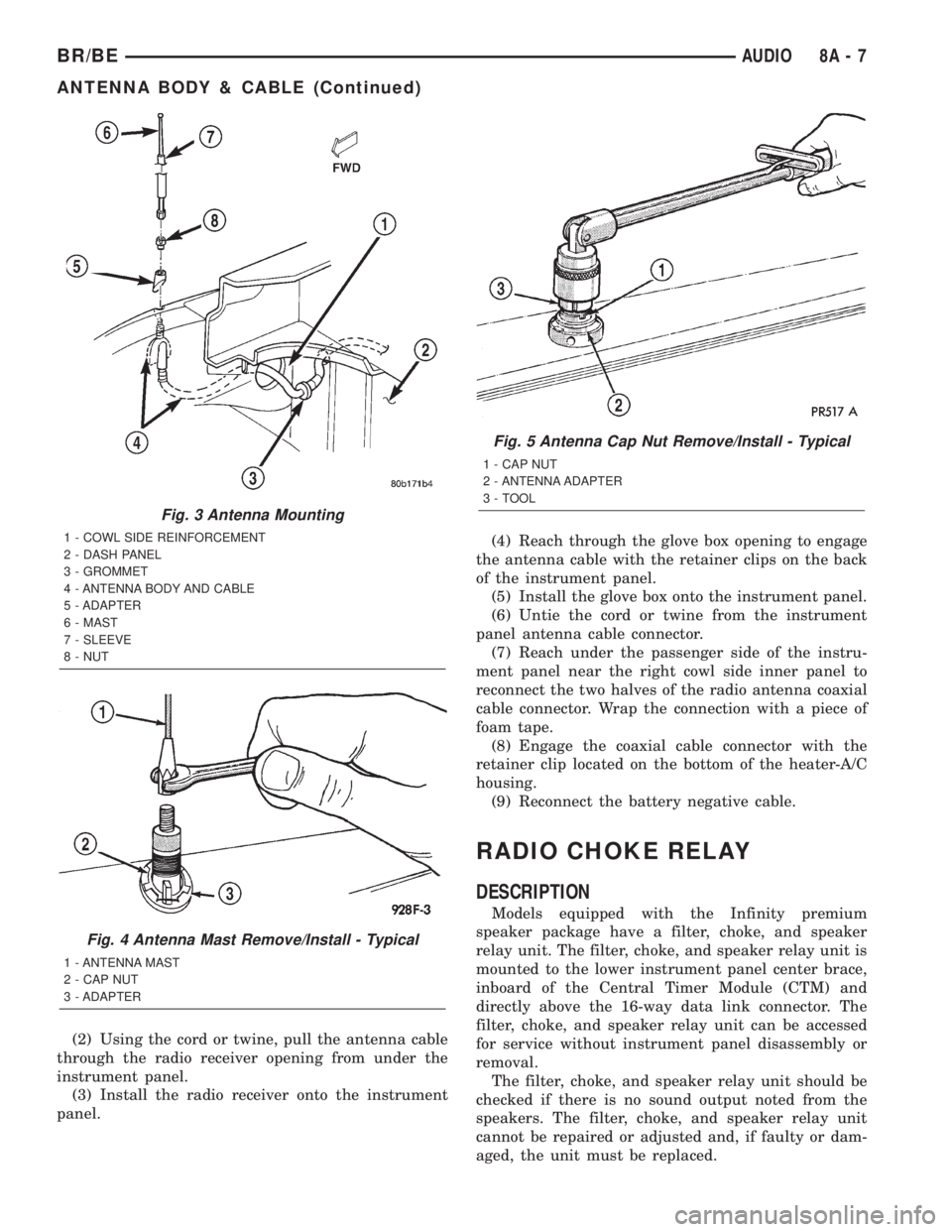
Fig. 3 Antenna Mounting
1 - COWL SIDE REINFORCEMENT
2 - DASH PANEL
3 - GROMMET
4 - ANTENNA BODY AND CABLE
5 - ADAPTER
6 - MAST
7 - SLEEVE
8 - NUT
Fig. 4 Antenna Mast Remove/Install - Typical
1 - ANTENNA MAST
2 - CAP NUT
3 - ADAPTER
Fig. 5 Antenna Cap Nut Remove/Install - Typical
1 - CAP NUT
2 - ANTENNA ADAPTER
3 - TOOL
BR/BEAUDIO 8A - 7
ANTENNA BODY & CABLE (Continued)
Page 345 of 2255

OPERATION
The filter, choke, and speaker relay unit is used to
control the supply of fused battery current to the
front door speaker-mounted dual amplifiers. The
speaker relay is energized by a fused 12 volt output
from the radio receiver whenever the radio is turned
on. For complete circuit diagrams, refer to the appro-
priate wiring information. The wiring information
includes wiring diagrams, proper wire and connector
repair procedures, details of wire harness routing
and retention, connector pin-out information and
location views for the various wire harness connec-
tors, splices and grounds.
DIAGNOSIS AND TESTING - RADIO CHOKE
RELAY
The filter, choke and speaker relay is used to
switch power to the individual speaker amplifiers
used with the Infinity premium speaker package.
The choke and relay are serviced only as a unit. If all
of the speakers are inoperative the filter, choke and
speaker relay unit should be considered suspect.
However, before replacement make the following
checks of the filter, choke and speaker relay circuits.
For complete circuit diagrams, refer to the appropri-
ate wiring information. The wiring information
includes wiring diagrams, proper wire and connector
repair procedures, details of wire harness routing
and retention, connector pin-out information and
location views for the various wire harness connec-
tors, splices and grounds.
(1) Check the fused B(+) fuse in the junction block.
If OK, go to Step 2. If not OK, replace the faulty
fuse.
(2) Check for battery voltage at the fused B(+) fuse
in the junction block. If OK, go to Step 3. If not OK,
repair the open fused B(+) circuit to the battery as
required.
(3) Disconnect the instrument panel wire harness
connector from the filter, choke and speaker relay
unit. Check for battery voltage at the fused B(+) cir-
cuit cavity of the instrument panel wire harness con-
nector for the filter, choke and speaker relay unit. If
OK, go to Step 4. If not OK, repair the open fused
B(+) circuit to the junction block fuse as required.
(4) Probe the ground circuit cavity of the instru-
ment panel wire harness connector for the filter,
choke and speaker relay unit. Check for continuity to
a good ground. There should be continuity. If OK, go
to Step 5. If not OK, repair the open ground circuit to
ground as required.
(5) Turn the ignition switch to the On position and
turn the radio on. Check for battery voltage at the
radio 12-volt output circuit cavity of the instrument
panel wire harness connector for the filter, choke and
speaker relay unit. If OK, go to Step 6. If not OK,repair the open radio 12-volt output circuit to the
radio as required.
(6) Turn the radio and ignition switches to the Off
position. Reconnect the instrument panel wire har-
ness connector to the filter, choke and speaker relay
unit. Check for battery voltage at the amplified
speaker (+) circuit cavity of the instrument panel
wire harness connector for the filter, choke and
speaker relay unit. There should be zero volts. Turn
the ignition and radio switches to the On position.
There should now be battery voltage. If OK, repair
the open amplified speaker (+) circuits to the speak-
er-mounted amplifiers as required. If not OK, replace
the faulty filter, choke and speaker relay unit.
REMOVAL
(1) Disconnect and isolate the battery negative
cable.
(2) Reach under the driver side of the instrument
panel near the 16-way data link connector and
inboard of the ash receiver to access the filter, choke,
and speaker relay (Fig. 6) .
(3) Disconnect the instrument panel wire harness
connector from the filter, choke and speaker relay
wire harness connector.
Fig. 6 Filter, Choke, and Speaker Relay Remove/
Install
1 - ASH RECEIVER HOUSING
2 - DATA LINK CONNECTOR
3 - CENTER BRACE
4 - SCREW
5 - CHOKE AND RELAY
6 - WIRE HARNESS CONNECTORS
8A - 8 AUDIOBR/BE
RADIO CHOKE RELAY (Continued)
Page 346 of 2255
(4) Remove the two screws that secure the filter,
choke, and speaker relay mounting bracket to the
instrument panel center brace.
(5) Remove the filter, choke, and speaker relay
unit from under the instrument panel.
INSTALLATION
(1) Position the filter, choke, and speaker relay
unit under the instrument panel.
(2) Install and tighten the two screws that secure
the filter, choke, and speaker relay mounting bracket
to the instrument panel center brace. Tighten the
screws to 2.7 N´m (24 in. lbs.).
(3) Reconnect the instrument panel wire harness
connector to the filter, choke and speaker relay wire
harness connector.
(4) Reconnect the battery negative cable.
INSTRUMENT PANEL
ANTENNA CABLE
REMOVAL
(1) Disconnect and isolate the battery negative
cable.
(2) Reach under the passenger side of the instru-
ment panel near the right cowl side inner panel to
disengage the coaxial cable connector from the
retainer clip located on the bottom of the heater-A/C
housing.
(3) Remove the foam tape to access the coaxial
cable connector. Disconnect the connector by pulling
it apart while twisting the metal connector halves.
Do not pull on the cable.
(4) Securely tie a suitable length of cord or twine
to the instrument panel half of the antenna coaxial
cable connector. This cord will be used to pull or
ªfishº the cable back into position during installation.
(5) Roll down the glove box from the instrument
panel. Refer to Body, Instrument Panel for the proce-
dures.
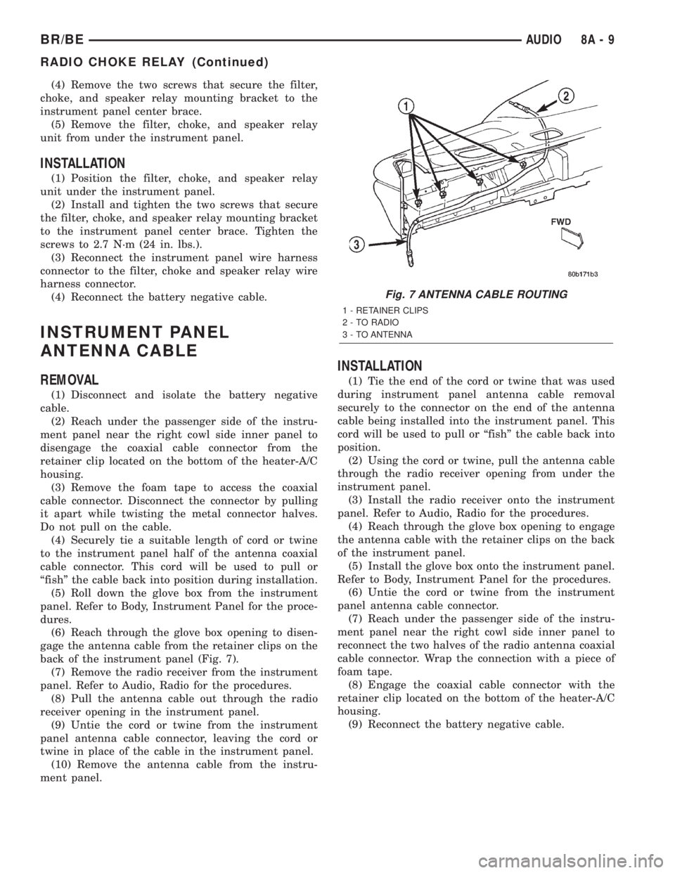
(6) Reach through the glove box opening to disen-
gage the antenna cable from the retainer clips on the
back of the instrument panel (Fig. 7).
(7) Remove the radio receiver from the instrument
panel. Refer to Audio, Radio for the procedures.
(8) Pull the antenna cable out through the radio
receiver opening in the instrument panel.
(9) Untie the cord or twine from the instrument
panel antenna cable connector, leaving the cord or
twine in place of the cable in the instrument panel.
(10) Remove the antenna cable from the instru-
ment panel.
INSTALLATION
(1) Tie the end of the cord or twine that was used
during instrument panel antenna cable removal
securely to the connector on the end of the antenna
cable being installed into the instrument panel. This
cord will be used to pull or ªfishº the cable back into
position.
(2) Using the cord or twine, pull the antenna cable
through the radio receiver opening from under the
instrument panel.
(3) Install the radio receiver onto the instrument
panel. Refer to Audio, Radio for the procedures.
(4) Reach through the glove box opening to engage
the antenna cable with the retainer clips on the back
of the instrument panel.
(5) Install the glove box onto the instrument panel.
Refer to Body, Instrument Panel for the procedures.
(6) Untie the cord or twine from the instrument
panel antenna cable connector.
(7) Reach under the passenger side of the instru-
ment panel near the right cowl side inner panel to
reconnect the two halves of the radio antenna coaxial
cable connector. Wrap the connection with a piece of
foam tape.
(8) Engage the coaxial cable connector with the
retainer clip located on the bottom of the heater-A/C
housing.
(9) Reconnect the battery negative cable.
Fig. 7 ANTENNA CABLE ROUTING
1 - RETAINER CLIPS
2 - TO RADIO
3 - TO ANTENNA
BR/BEAUDIO 8A - 9
RADIO CHOKE RELAY (Continued)