2002 DODGE RAM CD changer
[x] Cancel search: CD changerPage 1285 of 2255

CHARGE AIR COOLER AND
PLUMBING
DESCRIPTION
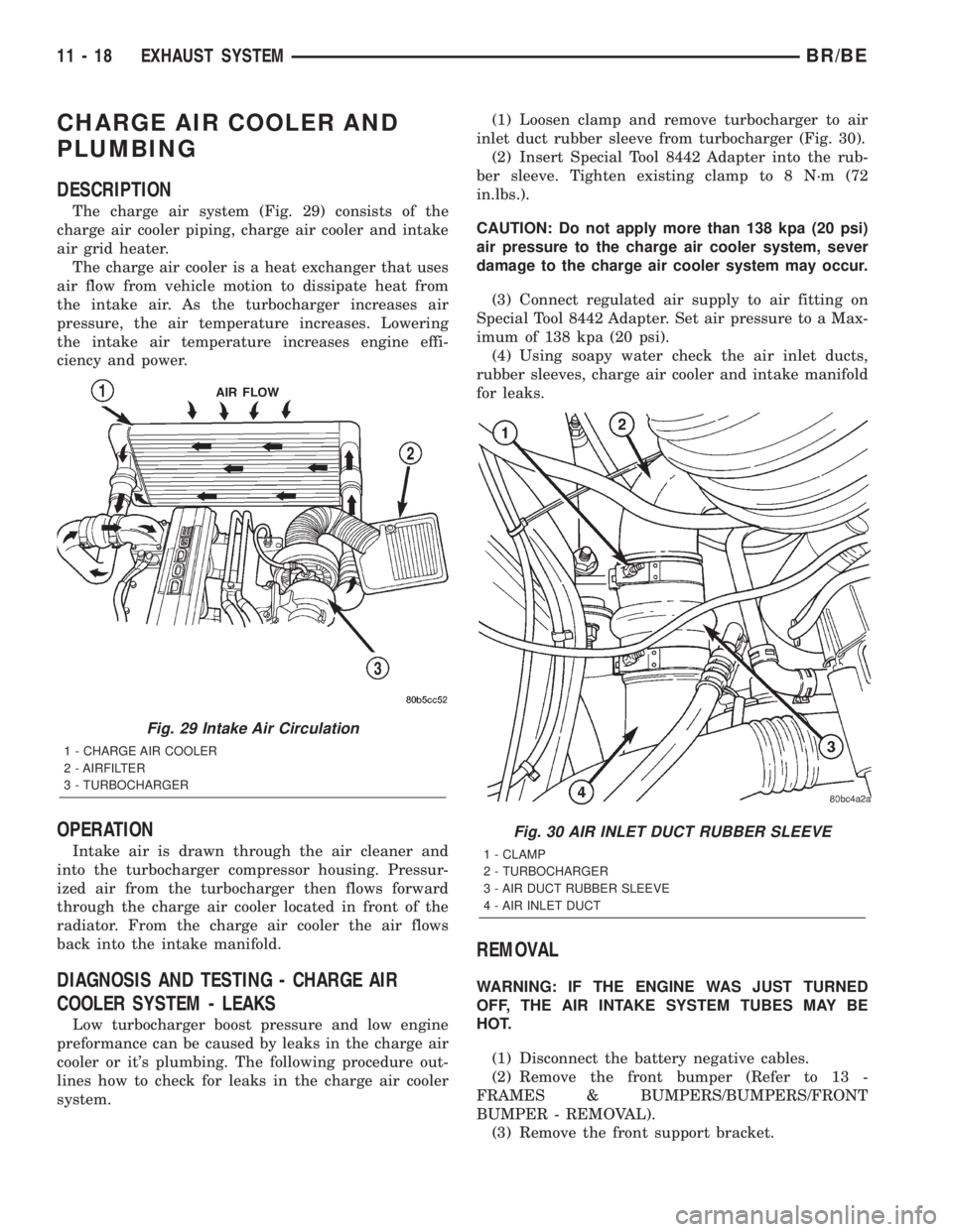
The charge air system (Fig. 29) consists of the
charge air cooler piping, charge air cooler and intake
air grid heater.
The charge air cooler is a heat exchanger that uses
air flow from vehicle motion to dissipate heat from
the intake air. As the turbocharger increases air
pressure, the air temperature increases. Lowering
the intake air temperature increases engine effi-
ciency and power.
OPERATION
Intake air is drawn through the air cleaner and
into the turbocharger compressor housing. Pressur-
ized air from the turbocharger then flows forward
through the charge air cooler located in front of the
radiator. From the charge air cooler the air flows
back into the intake manifold.
DIAGNOSIS AND TESTING - CHARGE AIR
COOLER SYSTEM - LEAKS
Low turbocharger boost pressure and low engine
preformance can be caused by leaks in the charge air
cooler or it's plumbing. The following procedure out-
lines how to check for leaks in the charge air cooler
system.(1) Loosen clamp and remove turbocharger to air
inlet duct rubber sleeve from turbocharger (Fig. 30).
(2) Insert Special Tool 8442 Adapter into the rub-
ber sleeve. Tighten existing clamp to 8 N´m (72
in.lbs.).
CAUTION: Do not apply more than 138 kpa (20 psi)
air pressure to the charge air cooler system, sever
damage to the charge air cooler system may occur.
(3) Connect regulated air supply to air fitting on
Special Tool 8442 Adapter. Set air pressure to a Max-
imum of 138 kpa (20 psi).
(4) Using soapy water check the air inlet ducts,
rubber sleeves, charge air cooler and intake manifold
for leaks.
REMOVAL
WARNING: IF THE ENGINE WAS JUST TURNED
OFF, THE AIR INTAKE SYSTEM TUBES MAY BE
HOT.
(1) Disconnect the battery negative cables.
(2) Remove the front bumper (Refer to 13 -
FRAMES & BUMPERS/BUMPERS/FRONT
BUMPER - REMOVAL).
(3) Remove the front support bracket.
Fig. 29 Intake Air Circulation
1 - CHARGE AIR COOLER
2 - AIRFILTER
3 - TURBOCHARGER
Fig. 30 AIR INLET DUCT RUBBER SLEEVE
1 - CLAMP
2 - TURBOCHARGER
3 - AIR DUCT RUBBER SLEEVE
4 - AIR INLET DUCT
11 - 18 EXHAUST SYSTEMBR/BE
Page 2170 of 2255

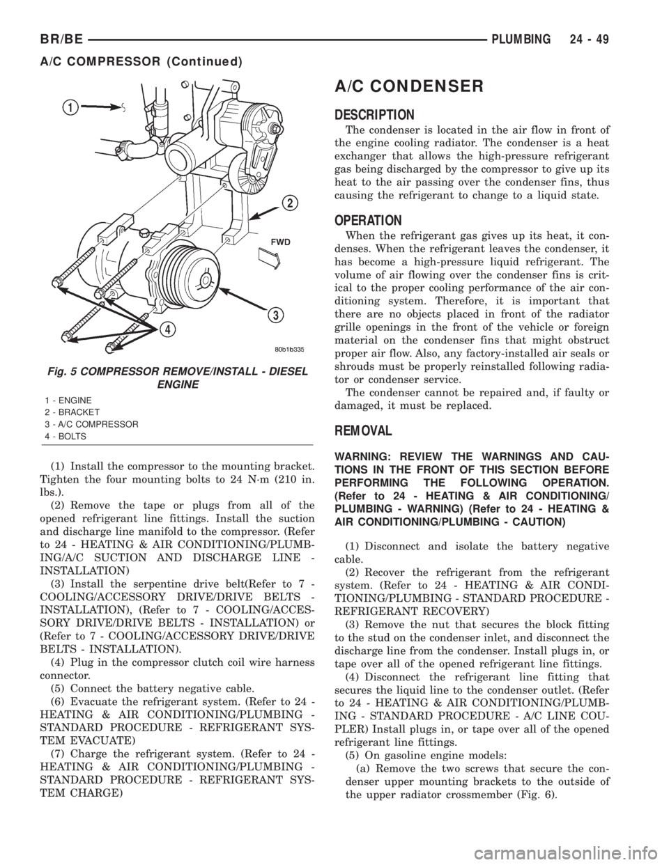
(1) Install the compressor to the mounting bracket.
Tighten the four mounting bolts to 24 N´m (210 in.
lbs.).
(2) Remove the tape or plugs from all of the
opened refrigerant line fittings. Install the suction
and discharge line manifold to the compressor. (Refer
to 24 - HEATING & AIR CONDITIONING/PLUMB-
ING/A/C SUCTION AND DISCHARGE LINE -
INSTALLATION)
(3) Install the serpentine drive belt(Refer to 7 -
COOLING/ACCESSORY DRIVE/DRIVE BELTS -
INSTALLATION), (Refer to 7 - COOLING/ACCES-
SORY DRIVE/DRIVE BELTS - INSTALLATION) or
(Refer to 7 - COOLING/ACCESSORY DRIVE/DRIVE
BELTS - INSTALLATION).
(4) Plug in the compressor clutch coil wire harness
connector.
(5) Connect the battery negative cable.
(6) Evacuate the refrigerant system. (Refer to 24 -
HEATING & AIR CONDITIONING/PLUMBING -
STANDARD PROCEDURE - REFRIGERANT SYS-
TEM EVACUATE)
(7) Charge the refrigerant system. (Refer to 24 -
HEATING & AIR CONDITIONING/PLUMBING -
STANDARD PROCEDURE - REFRIGERANT SYS-
TEM CHARGE)
A/C CONDENSER
DESCRIPTION
The condenser is located in the air flow in front of
the engine cooling radiator. The condenser is a heat
exchanger that allows the high-pressure refrigerant
gas being discharged by the compressor to give up its
heat to the air passing over the condenser fins, thus
causing the refrigerant to change to a liquid state.
OPERATION
When the refrigerant gas gives up its heat, it con-
denses. When the refrigerant leaves the condenser, it
has become a high-pressure liquid refrigerant. The
volume of air flowing over the condenser fins is crit-
ical to the proper cooling performance of the air con-
ditioning system. Therefore, it is important that
there are no objects placed in front of the radiator
grille openings in the front of the vehicle or foreign
material on the condenser fins that might obstruct
proper air flow. Also, any factory-installed air seals or
shrouds must be properly reinstalled following radia-
tor or condenser service.
The condenser cannot be repaired and, if faulty or
damaged, it must be replaced.
REMOVAL
WARNING: REVIEW THE WARNINGS AND CAU-
TIONS IN THE FRONT OF THIS SECTION BEFORE
PERFORMING THE FOLLOWING OPERATION.
(Refer to 24 - HEATING & AIR CONDITIONING/
PLUMBING - WARNING) (Refer to 24 - HEATING &
AIR CONDITIONING/PLUMBING - CAUTION)
(1) Disconnect and isolate the battery negative
cable.
(2) Recover the refrigerant from the refrigerant
system. (Refer to 24 - HEATING & AIR CONDI-
TIONING/PLUMBING - STANDARD PROCEDURE -
REFRIGERANT RECOVERY)
(3) Remove the nut that secures the block fitting
to the stud on the condenser inlet, and disconnect the
discharge line from the condenser. Install plugs in, or
tape over all of the opened refrigerant line fittings.
(4) Disconnect the refrigerant line fitting that
secures the liquid line to the condenser outlet. (Refer
to 24 - HEATING & AIR CONDITIONING/PLUMB-
ING - STANDARD PROCEDURE - A/C LINE COU-
PLER) Install plugs in, or tape over all of the opened
refrigerant line fittings.
(5) On gasoline engine models:
(a) Remove the two screws that secure the con-
denser upper mounting brackets to the outside of
the upper radiator crossmember (Fig. 6).
Fig. 5 COMPRESSOR REMOVE/INSTALL - DIESEL
ENGINE
1 - ENGINE
2 - BRACKET
3 - A/C COMPRESSOR
4 - BOLTS
BR/BEPLUMBING 24 - 49
A/C COMPRESSOR (Continued)
Page 2177 of 2255

(3) Tighten the accumulator retaining band screw
to 4.5 N´m (40 in. lbs.).
(4) Remove the tape or plugs from the refrigerant
line fittings on the suction line and the accumulator
outlet. Connect the suction line refrigerant line cou-
pler to the accumulator outlet. (Refer to 24 - HEAT-
ING & AIR CONDITIONING/PLUMBING -
STANDARD PROCEDURE - A/C LINE COUPLERS)
(5) Reinstall the a/c low pressure switch on the
accumulator. (Refer to 24 - HEATING & AIR CON-
DITIONING/CONTROLS/A/C LOW PRESSURE
SWITCH - INSTALLATION)
(6) Connect the battery negative cable.
(7) Evacuate the refrigerant system. (Refer to 24 -
HEATING & AIR CONDITIONING/PLUMBING -
STANDARD PROCEDURE - REFRIGERANT SYS-
TEM EVACUATE)
(8) Charge the refrigerant system. (Refer to 24 -
HEATING & AIR CONDITIONING/PLUMBING -
STANDARD PROCEDURE - REFRIGERANT SYS-
TEM CHARGE)
NOTE: If the accumulator is replaced, add 60 milli-
liters (2 fluid ounces) of refrigerant oil to the refrig-
erant system. Use only refrigerant oil of the type
recommended for the compressor in the vehicle.
HEATER CORE
DESCRIPTION
The heater core is located in the HVAC housing,
under the instrument panel. It is a heat exchanger
made of rows of tubes and fins.
The heater core is not repairable and if damaged it
must be replaced.
OPERATION
Engine coolant is circulated through heater hoses
to the heater core at all times. As the coolant flows
through the heater core, heat removed from the
engine is transferred to the heater core fins and
tubes. Air directed through the heater core picks up
the heat from the heater core fins. The blend door
allows control of the heater output air temperature
by controlling how much of the air flowing through
the HVAC housing is directed through the heater
core. The blower motor speed controls the volume of
air flowing through the HVAC housing.
The heater core cannot be repaired and, if faulty or
damaged, it must be replaced.
REMOVAL
(1) Remove the HVAC housing from the vehicle.
(Refer to 24 - HEATING & AIR CONDITIONING/
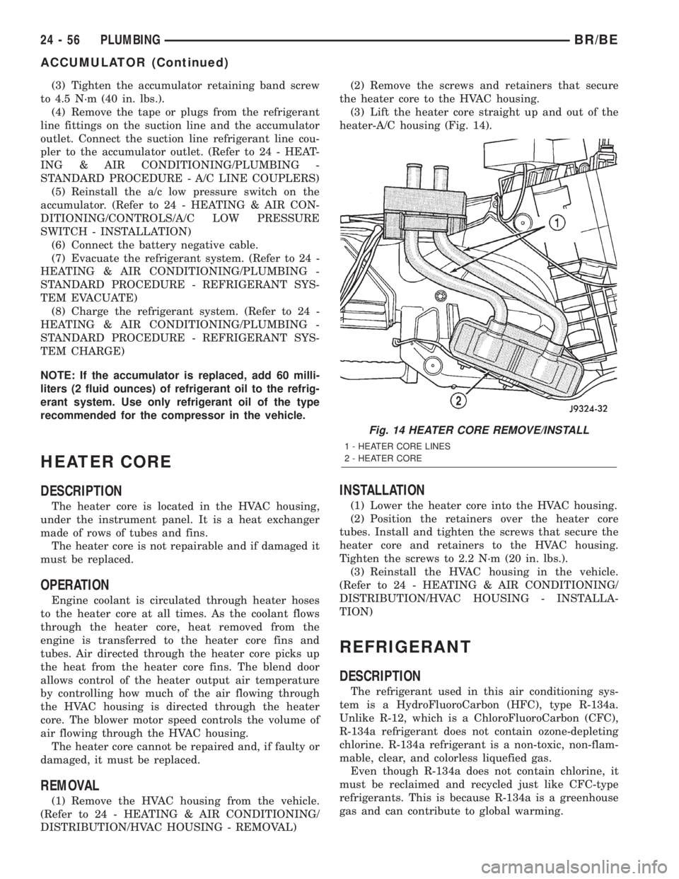
DISTRIBUTION/HVAC HOUSING - REMOVAL)(2) Remove the screws and retainers that secure
the heater core to the HVAC housing.
(3) Lift the heater core straight up and out of the
heater-A/C housing (Fig. 14).
INSTALLATION
(1) Lower the heater core into the HVAC housing.
(2) Position the retainers over the heater core
tubes. Install and tighten the screws that secure the
heater core and retainers to the HVAC housing.
Tighten the screws to 2.2 N´m (20 in. lbs.).
(3) Reinstall the HVAC housing in the vehicle.
(Refer to 24 - HEATING & AIR CONDITIONING/
DISTRIBUTION/HVAC HOUSING - INSTALLA-
TION)
REFRIGERANT
DESCRIPTION
The refrigerant used in this air conditioning sys-
tem is a HydroFluoroCarbon (HFC), type R-134a.
Unlike R-12, which is a ChloroFluoroCarbon (CFC),
R-134a refrigerant does not contain ozone-depleting
chlorine. R-134a refrigerant is a non-toxic, non-flam-
mable, clear, and colorless liquefied gas.
Even though R-134a does not contain chlorine, it
must be reclaimed and recycled just like CFC-type
refrigerants. This is because R-134a is a greenhouse
gas and can contribute to global warming.
Fig. 14 HEATER CORE REMOVE/INSTALL
1 - HEATER CORE LINES
2 - HEATER CORE
24 - 56 PLUMBINGBR/BE
ACCUMULATOR (Continued)